
EN - Instructions and warnings for installation and use
IT - Istruzioni ed avvertenze per l’installazione e l’uso
FR - Instructions et avertissements pour l’installation et l’utilisation
ES - Instrucciones y advertencias para la instalación y el uso
DE - Installierungs-und Gebrauchsanleitungen und Hinweise
PL - Instrukcje i ostrzeżenia do instalacji i użytkowania
NL - Aanwijzingen en aanbevelingen voor installatie en gebruik
Moon
Control unit
MC824H
Page is loading ...

ENGLISH
Contents
GENERAL SAFETY WARNINGS AND PRECAUTIONS. . . . . . . . . . . . . . . 1
Safety warnings. . . . . . . . . . . . . . . . . . . . . . . . . . . . . . . . . . . . . . . . . . . . . . . 1
Installation warnings . . . . . . . . . . . . . . . . . . . . . . . . . . . . . . . . . . . . . . . . . . . 1
Safety warnings. . . . . . . . . . . . . . . . . . . . . . . . . . . . . . . . . . . . . . . . . . . . . . . 1
1 - PRODUCT DESCRIPTION AND INTENDED USE . . . . . . . . . . . . . . . . 1
2 - INSTALLATION . . . . . . . . . . . . . . . . . . . . . . . . . . . . . . . . . . . . . . . . . . . 1
2.1 - Preliminary checks for installation . . . . . . . . . . . . . . . . . . . . . . . . . . . . . 1
2.2 - Product application limits. . . . . . . . . . . . . . . . . . . . . . . . . . . . . . . . . . . . 2
2.3 - Typical system. . . . . . . . . . . . . . . . . . . . . . . . . . . . . . . . . . . . . . . . . . . . 2
2.4 - Installation of control unit. . . . . . . . . . . . . . . . . . . . . . . . . . . . . . . . . . . . 2
3 - ELECTRICAL CONNECTIONS . . . . . . . . . . . . . . . . . . . . . . . . . . . . . . . 2
3.1 - Description of electrical connections . . . . . . . . . . . . . . . . . . . . . . . . . . . 2
3.2 - Electrical connections of MC824H control unit . . . . . . . . . . . . . . . . . . . 2
3.3 - Connection of other devices to MC824H. . . . . . . . . . . . . . . . . . . . . . . . 3
3.4 - Connected device address assignment to MC824H . . . . . . . . . . . . . . . 3
3.5 - Initial start-up and electrical connections . . . . . . . . . . . . . . . . . . . . . . . . 3
3.6 - Learning of the devices connected to MC824H. . . . . . . . . . . . . . . . . . . 3
3.7 - Selecting the type of gearmotor connected to MC824H
and learning the mechanical stop positions . . . . . . . . . . . . . . . . . . . . . 3
3.7.1 - Learning in automatic mode . . . . . . . . . . . . . . . . . . . . . . . . . . . 4
3.7.2 - Learning in manual mode . . . . . . . . . . . . . . . . . . . . . . . . . . . . . 4
3.7.3 - Learning in combined mode . . . . . . . . . . . . . . . . . . . . . . . . . . . 4
3.8 - Checking movement of gate leafs . . . . . . . . . . . . . . . . . . . . . . . . . . . . . 4
4 - TESTING AND COMMISSIONING . . . . . . . . . . . . . . . . . . . . . . . . . . . . 4
4.1 - Testing . . . . . . . . . . . . . . . . . . . . . . . . . . . . . . . . . . . . . . . . . . . . . . . . . 4
4.2 - Commissioning . . . . . . . . . . . . . . . . . . . . . . . . . . . . . . . . . . . . . . . . . . . 5
5 - PROGRAMMING . . . . . . . . . . . . . . . . . . . . . . . . . . . . . . . . . . . . . . . . . . 5
5.1 - Level one programming (ON-OFF functions) . . . . . . . . . . . . . . . . . . . . . 5
5.2 - Level two programming (adjustable parameters) . . . . . . . . . . . . . . . . . . 6
5.3 - Special functions. . . . . . . . . . . . . . . . . . . . . . . . . . . . . . . . . . . . . . . . . . 7
5.4 - Deletion of memory . . . . . . . . . . . . . . . . . . . . . . . . . . . . . . . . . . . . . . . . 7
6 - WHAT TO DO IF… (troubleshooting guide). . . . . . . . . . . . . . . . . . . . . 8
7 - FURTHER DETAILS . . . . . . . . . . . . . . . . . . . . . . . . . . . . . . . . . . . . . . . . 9
7.1 - Connecting a radio receiver. . . . . . . . . . . . . . . . . . . . . . . . . . . . . . . . . . 9
7.2 - Connecting Oview programming unit. . . . . . . . . . . . . . . . . . . . . . . . . . . 9
7.3 - Connecting the Solemyo solar energy system . . . . . . . . . . . . . . . . . . . . 9
7.4 - Connecting model PS324 buffer battery . . . . . . . . . . . . . . . . . . . . . . . . 9
8 - PRODUCT MAINTENANCE . . . . . . . . . . . . . . . . . . . . . . . . . . . . . . . . 10
PRODUCT DISPOSAL . . . . . . . . . . . . . . . . . . . . . . . . . . . . . . . . . . . . . . . 10
TECHNICAL CHARACTERISTICS OF THE PRODUCT . . . . . . . . . . . . . 10
CE DECLARATION OF CONFORMITY . . . . . . . . . . . . . . . . . . . . . . . . . . . . I
Instructions and warnings for the user . . . . . . . . . . . . . . . . . . . . . . . . . . V
Images . . . . . . . . . . . . . . . . . . . . . . . . . . . . . . . . . . . . . . . . . . . . . . . . . . . XII
MC824H is an electronic control unit for the automation of swing gates.
IMPORTANT! – Any other use than as specified herein or in environ-
mental conditions other than as stated in this manual is to be consid-
ered improper and is strictly prohibited!
The control unit is ready for connection to devices belonging to the Opera sys-
tem, the Bluebus system and the Solemyo solar energy supply system.
If powered from the mains, it can house a buffer battery (model PS324, option-
al accessory), which ensures that the automation can perform a number of
manoeuvres for several hours in the event of a power failure.
Other available accessories include the dedicated receivers with “SM” fitting
(SMXI, OXI, etc.).
PRODUCT DESCRIPTION AND
INTENDED USE
1
Safety warnings
• IMPORTANT! – This manual contains important instructions and warn-
ings for personal safety. Incorrect installation could cause serious physical
injury. Read all parts of the manual carefully before starting work. If in doubt,
interrupt installation and contact the Nice Service Centre for clarifications.
• IMPORTANT! – Important instructions: keep this manual in a safe place
to enable future product maintenance and disposal procedures.
• IMPORTANT! – Under the latest European legislation, automatic door
and gate installations must be compliant with the standards specified
in Directive 2006/42/EC (formerly 98/37/EC) (the Machinery Directive)
and the standards EN 12445, EN 12453, EN 12635 and EN 13241-1 in
particular, which enable conformity of the automated functionality to
be de clared. In the light of the above, all work involving installation,
connection, testing and maintenance of the product must be carried
out exclusively by qualified and competent technicians!
Installation warnings
• Before commencing installation, check that the product is suitable for the
intended kind of use (see paragraph 2.2 “Limits of use” and “Product technical
specifications”). If not suitable, do NOT proceed with installation.
• The contents of this manual refer to a standard system as described in fig. 2a.
• All installation and maintenance work must be carried out with the au -
to mation system disconnected from the electricity supply. If the power
discon nection device cannot be seen from where the automation system is
po sitioned, then before starting work a notice must be attached to the discon-
nection device bearing the words “CAUTION! MAINTENANCE IN PRO -
GRESS”.
• On the power line to the system, install a device for disconnection from the
power mains with a gap between contacts that assures complete disconnec-
tion in the conditions of overvoltage category III.
• Connect the control unit to an electric power line equipped with an earthing
system.
• During installation, handle the product with care, avoiding the risk of crushing,
impact, dropping or contact with any type of liquid. Never place the product
near sources of heat or expose to naked flames. This may damage product
components and cause malfunctions, fire or hazardous situations. If this oc -
curs, suspend installation immediately and contact the Nice Service Centre.
• Never make modifications to any part of the product. Operations other than as
specified can only cause malfunctions. The manufacturer declines all liability
for damage caused by makeshift modifications to the product.
• The product’s packaging materials must be disposed of in full compliance with
local regulations.
Safety warnings
• The product should not be used by children or people with impaired physical,
sensorial or mental capacities or who have not received adequate training in
the safe use of the product.
• In the vicinity of the automation children must be supervised to ensure that
they do not play with it.
• Do not allow children to play with the fixed control devices. Keep remote con-
trol devices out of the reach of children.
GENERAL SAFETY WARNINGS AND PRECAUTIONS
2.1 - Preliminary checks for installation
Before proceeding with installation, check the condition of the product compo-
nents, suitability of the selected model and conditions of the intended installa-
tion environment:
• Ensure that all material used is in perfect condition and suitable for use.
• Ensure that all conditions of use remain within the limits of product applica-
tion (paragraph 2.2) and within the limit values stated in the “Product techni-
cal specifications”.
• Ensure that the selected installation environment is compatible with the over-
all dimensions of the product (fig. 1).
• Ensure that the selected surfaces for product installation are solid and guar-
antee a stable fixture.
INSTALLATION
2
English – 1
EN

ELECTRICAL CONNECTIONS
3
The electrical connection of the various devices (photocells, digital keyboard,
transponder card readers, etc.) contained in the automation with the control
unit must be made by means of the Nice “Bluebus” system.
3.1 - Description of electrical connections (fig. 6)
AERIAL input for the radio receiver aerial
FLASH output for 1 flashing light with 12V (maximum 21W) bulb. [*]
ELS output for 12Vac (maximum 15VA) electric lock. [*]
S.C.A. “Open Gate Light”: output for 1 indication lamp (24V maximum
4W). [*]
BLUEBUS input for compatible devices (MOFB, MOFOB, MOB and MOTB);
they are connected in parallel using two conductors through which
both the electricity supply and the communication signals travel;
no polarity needs to be observed. The electrical connection to be
used is of the parallel type and no polarity needs to be observed.
During the learning stage, the control unit will recognise individually
all devices connected to it thanks to a unique code. Each time a
device is added or eliminated, it will be necessary to make the
control unit perform the learning operation (see paragraph 3.6).
STOP input for devices that cause the immediate interruption of the
manoeuvre in progress (with a short reverse run); NO and NC
contacts, as well as devices with 8.2 kΩ constant resistance
output (sensitive edges) can be connected to this input. Each
device connected to this input is recognised individually by the
control unit during the learning stage (paragraph 3.6); in this stage,
if the control unit detects any variations with respect to the learned
state, it causes a STOP. One or more devices of the same or
different kinds can be connected to this input:
– connect a number of NO devices in parallel without quantity limits;
– several NC devices can be connected in series, with no limits as
to quantity;
– connect 2 devices with 8.2 kΩ constant resistance output in
parallel. If there are more than 2 devices, they must be connected in
a cascade with just one 8.2 kΩ termination resistance;
– connect 2 NO and NC devices in parallel, placing a 8.2 kΩ
resistance in series on the NC contact (this also allows for a
combination of three devices NO - NC and 8.2 kΩ)
P. P. input for devices which control Step-by-Step manoeuvres.
NO contacts can be connected to this input
OPEN input for devices which control only opening manoeuvre.
NO contacts can be connected to this input
CLOSE input for devices which control only closure manoeuvre. NO contacts
can be connected to this input
ENC1 input encoder – gearmotor 1 (terminal 1, 2); it is not necessary to
observe any polarity
ENC2 input encoder – gearmotor 2 (terminal 4, 5); it is not necessary to
observe any polarity
M1 output for gearmotor 1 (terminal 7, 8, 9)
M2 output for gearmotor 2 (terminal 10, 11, 12)
[*] The FLASH, ELS and S.C.A. outputs can be programmed with other func-
tions (see “TABLE 5 - 1st level functions”; or via Oview programmer, see chap-
ter 7.2).
3.2 - Electrical connections of MC824H control unit
After mounting the control unit box and preparing the electrical cable holes
(chapter 2.4 and fig. 3), make the electrical connections:
IMPORTANT!
– All electrical connections must be made with the unit disconnected
from the mains power supply and with the buffer battery disconnected,
if present in the automation.
– Connections must be made exclusively by qualified personnel.
– The electrical power line must be fitted with a device that enables complete
disconnection of the automation from the mains. The disconnection device
must have a gap between contacts that ensures complete disconnection in the
conditions of overvoltage category III, in compliance with installation regula-
tions. If necessary, this device guarantees rapid and safe disconnection from
the mains, and therefore should be located in view of the automation. Howev-
er, if located in a concealed position, it must have a system that blocks against
inadvertent or unauthorised reconnection to prevent all risks. The disconnec-
tion device is not supplied with the product.
01. First connect the electric power cable (fig. 4) and secure by means of the
cable clamp;
02. Then connect the electric cables of motors M1 and M2, observing the
symbols on the label (fig. 5):
• Make sure that the fixing zone is not subject to flooding. If necessary, mount
the product raised from the ground.
• Ensure that the space around the product enables easy and safe access.
• Make sure that all the electrical cables used are of the type listed in
Table 1.
• Make sure that the automation is provided with mechanical stops on both
closing and opening.
2.2 - Product application limits
The product may be used exclusively with gearmotors METRO (model ME3024),
MOBY (model MB4024-MB5024), HYPPO (model HY7024-HY7124), TOONA
(model TO4024-TO5024-TO7024), X-metro (model XME2124), Big-Metro
(BM5024), Metroelite, Wingoelite and in accordance with the corresponding
usage limits.
2.3 - Typical system
Fig. 2a shows an example of an automation system set up with Nice components:
a - Control unit
b - Gearmotor
c - Flashing light
d - Photocell
e - Digital keyboard - Transponder reader - Key selector
f - Photocell post
g - Opening mechanical stops
h - Closure mechanical stops
i - Electric lock
These parts are positioned according to a typical standard layout. With refer-
ence to fig. 2a, locate the approximate position for installation of each com-
ponent making up the system. Important – Before installation, prepare the
electrical cables needed for your system, referring to fig. 2b and “Table 1 -
Technical characteristics of electrical cables”.
Important – During installation of ducting for electrical cables and the intro-
duction of cables into the control unit enclosure, be aware that due to possible
water deposits in the junction boxes, the connecting ducts may form conden-
sation inside the control unit which is liable to damage the electronic circuits.
2.4 - Installation of control unit
To mount the control unit, proceed as shown in fig. 3:
01. Open the control unit box by undoing the relevant screws (fig. 3-A);
02. Prepare the electrical cable routing holes (fig. 3-B);
03. Mount the box (fig. 3-C);
04. The electrical connections can now be made: see chapter 3.
Important! – To prepare the inlets for the electrical cable ducting, holes must
be drilled in the lower side of the control unit box. Note – If necessary, the lat-
eral cable inlet may be used, but only with the aid of suitable duct fittings.
To install the other devices present in the automation, refer to the relevant
instruction manuals.
2 – English
EN
Connection Cable type Maximum admissible length
A: CONTROL UNIT POWER cable 1 cable 3 x 1,5 mm
2
30 m (note 1)
B: FLASHING LIGHT with aerial cable 1 cable 2 x 0,5 mm
2
20 m
1 shielded cable type RG58 20 m (less than 5 m recommended)
C: BLUEBUS DEVICES cable 1 cable 2 x 0,5 mm
2
20 m (note 2)
D: KEY-OPERATED SELECTOR SWITCH cable 2 cables 2 x 0,5 mm
2
(note 3) 50 m
E: GEARMOTOR POWER cable 1 cable 3 x 1,5 mm
2
(note 4) 10 m
F: ENCODER CONNECTION cable 1 cable 2 x 1 mm
2
(note 4) 10 m
G: ELECTRIC LOCK CONNECTION 1 cable 2 x 1 mm
2
10 m
Note 1 – If the power cable is longer than 30 m, a cable with a larger cross-section is required (3 x 2.5 mm
2
) and safety earthing is necessary in the vicinity
of the automation.
Note 2 – If the Bluebus cable is longer than 20 m (up to max. 40 m), a cable with a larger cross-section is required (2 x 1 mm
2
).
Note 3 – These 2 cables can be replaced by a single 4 x 0.5 mm
2
cable.
Note 4 – These 2 cables can be replaced by a single 5 x 1.5 mm
2
cable.
IMPORTANT! – The cables used must be suited to the installation environment.
TABLE 1 - Technical specifications of electrical cables (fig. 2b)

The control unit is able to recognise the various connected devices individually
through the self-learning procedure and detect possible faults. For this reason
it is necessary to perform self-learning every time a new device is added or an
existing device is removed.
To indicate when the self-learning procedure is required, LEDs L1 and L2 on
the control unit (fig. 7) emit a number of slow flashes:
01. Press and hold down and “Set” keys at the same time (fig. 7).
02. Release the keys when LEDs L1 and L2 start flashing quickly (after approx.
3 seconds).
03. Wait a few seconds for the control unit to complete the device learning
phase.
04. At the end of this phase, the “Stop” LED must be lit and LEDs “L1” and
“L2” must be turned off (LEDs L3 and L4 may start flashing).
3.7 - Selecting the type of gearmotor connected to MC824H
and learning the mechanical stop positions
After learning the devices (paragraph 3.6), the type of motors connected must
be selected (see Table 3) and the positions of the mechanical stops must also
be learnt (maximum opening and maximum closing). There are three ways to
perform this procedure: automatic, manual and combined.
In automatic mode
, the control unit learns the positions of the mechanical
stops and calculates the most suitable offset value for the leafs (SA and SC,
fig. B).
In manual mode
, the eight positions of the mechanical stops (fig. B) are pro-
grammed one by one, moving the leafs to the required points. The position to
program is identifiable by the flashing status of one of the eight leds (L1-L8),
see Table 4.
In combined mode
, the automatic procedure can be performed and then, using
the manual procedure, one or more positions may be modified, with the excep-
tion of positions “0” and “1” (fig. B) which coincide with the positions of the
mechanical stops.
a) connect the motor that activates the lower leaf (the second to start the
opening manoeuvre) to terminal M1 and then the respective encoder to ter-
minals 1-2;
b) connect the motor that activates the upper leaf (the first to start the
opening manoeuvre) to terminal M2 and then the respective encoder to ter-
minals 4-5;
IMPORTANT! – If there is only one gearmotor in the system, con-
nect it to terminal M2 leaving terminal M1 free;
03. Then connect the electric cables of the various devices present, with refer-
ence to fig. 6 and paragraph 3.3 Note – To facilitate cable connections,
the terminals can be removed from their seats;
3.3 - Connection of other devices to MC824H
If further devices present in the system need to be powered, for example a
transponder card reader or the key selector light, these devices can be con-
nected to the control unit using terminals “P.P. (positive)” and “STOP (negative)”
(fig. 6). The power supply voltage is 24 Vdc, -30% ÷ +50%, with maximum
available current 200 mA.
Note – The voltage present on terminals “P.P.” and “STOP” remains connected
even when the “Stand By” function is activated on the card.
3.4 - Connected device address assignment to MC824H
To enable control unit recognition of the devices connected to the BlueBus sys-
tem, they need to be routed. This operation must be performed by positioning
the electric jumper correctly on each device; see the relative instruction manual
of individual devices: see fig. A and Table 2.
At the end of the installation procedure or following the removal of photocells or
other devices, the self-learning procedure for these devices must be per-
formed. See paragraph 3.6.
3.5 - Initial start-up and electrical connections
After powering up the control unit, perform the following checks:
• After a few seconds, make sure that the “Bluebus” LED (fig. 7) flashes regu-
larly with a frequency of about one flash per second.
• Make sure that the LEDs on the photocells (fig. 7) flash (both on TX and RX).
The type of flashing is not important during this stage.
• Make sure that the flashing light connected to the FLASH output is off.
If the above conditions are not satisfied, switch off the power supply to the con-
trol unit and check the electrical connections previously made.
3.6 - Learning of the devices connected to MC824H
After the initial power-up, the control unit must be able to recognise the devices
connected to the “Bluebus” and “Stop” inputs.
IMPORTANT! – The learning procedure must be performed even if no
device is connected to the control unit.
English – 3
EN
A
0
11
A
SC
SA
A
0
M1 M2
B
POSITIONS
TABLE 4
Position Led Description
Position 0
(motor 1)
Position 0
(motor 2)
Position SA
(motor 2)
Position A
(motor 1)
Position A
(motor 2)
Position SC
(motor 1)
Position 1
(motor 1)
Position 1
(motor 2)
Maximum closing position: when leaf 1 reaches closing
mechanical stop
Maximum closing position: when leaf 2 reaches closing
mechanical stop
Opening offset: when leaf 2 passes this position the opening
of leaf 1 begins
Required opening position: position in which the leaf connect-
ed to motor 1 must stop at the end of an opening manoeuvre.
This position does not have to coincide with the opening
mechanical stop, and can be selected as required from posi-
tion “0” or “1”.
Required opening position: position in which the leaf connect-
ed to motor 2 must stop at the end of an opening manoeuvre.
This position does not have to coincide with the opening
mechanical stop, and can be selected as required from posi-
tion “0” or “1”.
Closing offset: when leaf 1 reaches this position, leaf 2 begins
to close
Maximum opening position: when leaf 1 reaches the opening
mechanical stop
Maximum opening position: when leaf 2 reaches the opening
mechanical stop
L1
L2
L3
L4
L5
L6
L7
L8
TABLE 2 - PHOTOCELL ADDRESSES
Photocell Jumpers
FOTO
External photocell h = 50 with trip on
closure (stops and inverts movement)
FOTO II
External photocell h = 100 with trip on closure
(stops and inverts movement)
FOTO 1
Internal photocell h = 50 with trip on closure
(stops and inverts movement) and opening
(stops and restarts when photocell is disengaged)
FOTO 1 II
Internal photocell h = 100 with trip on closure
(stops and inverts movement) and opening
(stops and restarts when photocell is disengaged)
FOTO 2
Internal photocell with trip on opening
(stops and inverts movement))
FOTO 2 II
Internal photocell with trip on opening
(stops and inverts movement)
FOTO 3
CONFIGURATION NOT ADMITTED
3.7.1 - Learning in automatic mode
01. Press and hold down “Set” and keys at the same time.
02. Release the keys when LED L1 begins to flash (motor selection: not per-
formed) or when any of the LEDs L1 ... L8 lights up (motor selection:
already performed).
TABLE 3
Led Gearmotor type Led Gearmotor type
L5 TO7024
L6 BM5024
L7 METROELITE
L8 WINGOELITE
L1 MB4024 - MB5024 -
HY7024 - HY7124
L2 ME3024
L3 TO4024 - XME2124
L4 TO5024

These are the most important phases of automation set-up for ensuring maxi-
mum system safety. The test can also be performed as a periodic check of
automation devices. Testing and commissioning of the automation must be
performed by skilled and qualified personnel, who are responsible for the tests
required to verify the solutions adopted according to the risks present, and for
ensuring observance of all legal provisions, standards and regulations, and in
particular all requirements of the standard EN 12445, which establishes the test
methods for checking automations for doors and gates. The additional devices
must undergo a specific test for functionality and correct interaction with
MC824H. Refer to the instruction manuals of the individual devices.
4.1 - Testing
The sequence of operations to be performed for testing and described below
refers to a typical system (fig. 2):
1 Ensure that everything stated in the “Installation warnings” chapter has
been observed.
2 Release the gearmotors for manual operation as described in the relevant
instruction manual. Pushing at the prescribed point for manual operation,
check that it is possible to open and close the leafs with a force lower than
390 N.
3 Lock the gearmotors (see relevant instruction manual).
4 Using the control devices (transmitter, key-operated selector switch or con-
trol pushbuttons, etc.), perform tests of opening, closing and stopping the
gate, and ensure that leaf movement corresponds to specifications. Test
several times to check for leaf movement and any defects in assembly or
adjustment and any possible points of friction.
5 Check operation of all system safety devices one at a time (photocells, sen-
sitive edges, etc.). Each time a device is activated the “BLUEBUS” LED on
the control unit must flash rapidly twice to confirm acknowledgement of the
event.
6 If hazardous situations generated by the moving leafs are protected by
means of impact force limitation, measure the force as specified in the stan-
TESTING AND COMMISSIONING
4
4 – English
EN
03. Press or keys within 10 seconds to go to the LED corresponding to
the type of gearmotor connected to the control unit (see Table 3);
04. Press and hold down
the “Set” key for at least 3 seconds to memorize the
selected gearmotor. After 3 sec. LED L1 starts flashing, then release the key;
05. Press and hold
keys “Set” and “” at the same time.
06. Release the keys when leds “L3” and “L4” start flashing quickly (after
approx. 3 seconds).
07. Ensure that the automation completes the following sequences of ma -
noeuvres:
a - Low speed closure of gearmotor M1 through to the mechanical stop
b - Low speed closure of gearmotor M2 through to the mechanical stop
c - low speed opening of gearmotor M2 and gearmotor M1 through to the
mechanical stop
d - High speed closure of gearmotors M1 and M2
Warnings:
– If the first manoeuvre (a) does not close the leaf controlled by motor M1 but
closes the one controlled by M2, press key “
” or “
” to stop the learning
phase. At this point, invert the connections of motors M1 and M2 on the ter-
minals on the control unit and then those of the respective encoders; after
this start the procedure from point 05;
– If the first two manoeuvres (a e b) are not “closing” but are “opening”, press
key “
” or “
” to stop the learning phase. At this point, on the gearmotor
that completed the opening manoeuvre, invert the polarity of the two wires of
gearmotor M1 (terminals 7 and 9 for M1; terminals 10 and 12 for M2) and
then start the procedure from point 05;
08. At the end of the Closing manoeuvre of the 2 motors (d), leds “L3” and “L4”
turn off to indicate the that the procedure has been completed correctly.
Warnings:
– During the automatic learning procedure, if a photocell trips or a device con-
nected to the “stop” input is activated, the procedure is interrupted and led
L1 starts flashing. To resume the learning process, the procedure must be
started again from point 05;
– The automatic learning procedure can be repeated at any time, also after
installation; for example following modifications to the position of the
mechanical stops.
3.7.2 - Learning in manual mode
Caution! – From step 05 onwards:
– to move from led L1 to L8
, briefly press key or (the led flashes to indi-
cate the current position);
– to move the motor
in one or the other direction, press and hold key or .
01. Press and hold down
“Set” and keys at the same time;
02. Release the keys when LED L1 begins to flash (motor selection: not per-
formed) or when any of the LEDs L1 ... L8 lights up (motor selection:
already performed);
03. Press or keys within 10 seconds to go to the LED corresponding to
the type of gearmotor connected to the control unit (see Table 3);
04. Press and hold down
the “Set” key for at least 3 seconds to memorize the
se lected gearmotor. After 3 sec. LED L1 starts flashing, then release the key;
05. LED
L1 flashes: position 0 of M1
To bring motor 1 to position 0 (fig. B): press and hold down
the or
keys. On reaching the position, release the key to stop the manoeuvre. To
memorise the position, press and hold down
the “Set” key for at least 3
seconds and then release it (after 2 seconds LED L1 remains on and on
releasing the “Set” key LED L2 begins flashing).
• LED
L2 flashes: position 0 of M2
To bring motor 2 to position 0 (fig. B): press and hold down the or
keys. On reaching the position, release the key to stop the manoeuvre. To
memorise the position, press and hold down the “Set” key for at least 3
seconds and then release it (after 2 seconds LED L2 remains on and on
releasing the “Set” key LED L3 begins flashing).
• LED
L3 flashes: position SA of M2
To bring motor 2 to position SA (fig. B): press and hold down the or
keys. On reaching the position, release the key to stop the manoeuvre. To
memorise the position, press and hold down the “Set” key for at least 3
seconds and then release it (after 2 seconds LED L3 remains on and on
releasing the “Set” key LED L4 begins flashing).
• LED
L4 flashes: position A of M1
To bring motor 1 to position A (fig. B): press and hold down the or
keys. On reaching the position, release the key to stop the manoeuvre. To
memorise the position, press and hold down the “Set” key for at least 3
seconds and then release it (after 2 seconds LED L4 remains on and on
releasing the “Set” key LED L5 begins flashing).
• LED
L5 flashes: position A of M2
To bring motor 2 to position A (fig. B): press and hold down the or
keys. On reaching the position, release the key to stop the manoeuvre. To
memorise the position, press and hold down the “Set” key for at least 3
seconds and then release it (after 2 seconds LED L5 remains on and on
releasing the “Set” key LED L6 begins flashing).
• LED
L6 flashes: position SC of M1
To bring motor 1 to position SA (fig. B): press and hold down the or
keys. On reaching the position, release the key to stop the manoeuvre. To
memorise the position, press and hold down the “Set” key for at least 3
seconds and then release it (after 2 seconds LED L6 remains on and on
releasing the “Set” key LED L7 begins flashing).
• LED
L7 flashes: position 1 of M1
To bring motor 1 to position 1 (fig. B): press and hold down the or
keys. On reaching the position, release the key to stop the manoeuvre. To
memorise the position, press and hold down the “Set” key for at least 3
seconds and then release it (after 2 seconds LED L7 remains on and on
releasing the “Set” key LED L8 begins flashing).
• LED
L8 flashes: position 1 of M2
To bring motor 2 to position 1 (fig. B): press and hold down the or
keys. On reaching the position, release the key to stop the manoeuvre. To
memorise the position, press and hold down the “Set” key for at least 3
seconds and then release it to exit programming (after 2 seconds LED L8
remains on until the “Set” key is released).
Note – Manual programming in a system with a single gearmotor: pro-
ceed as described at the beginning of this paragraph from step 01. At step 05
proceed as follows:
- Program the positions related to led L1 (0 of M1) and L7 (1 of M1) as
follows: press and hold the “Set” key for at least 3 seconds and then release
(after 2 seconds the LED remains on, and on release of the “Set” key the next
LED begins flashing).
- Do not program
the positions related to led L3 (SA of M2) - L4 (A of
M1) - L6 (SC of M1): briefly press key or to move between positions.
3.7.3 - Learning in combined mode
Perform this procedure after completing the automatic learning cycle:
01. Press and hold
keys “Set” and “” at the same time.
02. Release the key when led L1 starts to flash (selection of motors: never
performed) or when any one of leds L1 to L8 lights up (selection of
motors: already performed);
03. Within 10 seconds, press key “” or “” to move the Led corresponding
to the type of gearmotor connected to the control unit (see Table 3);
04. Press and hold the key “Set” for at least 3 seconds, to memorise the
selected gearmotor. After the 3-second interval, led “L1” starts flashing; at
this point release the key;
05. Briefly press key “” or “” to move the flashing led (L1-L8) to the position
to be programmed and proceed for each position, as described in step 05
of the manual learning procedure (paragraph 3.7.2).
Repeat this operation for all other positions to be modified.
To complete the manual learning process, press key “” repeatedly to move
the led that flashing beyond position L8.
3.8 - Checking movement of gate leafs
At the end of the learning procedure, it is advisable to make the control unit per-
form a few opening and closing manoeuvres to ensure that the gate moves cor-
rectly and to check for installation or setting defects.
01. Press “Open”. Verify correct offset of the leafs on opening and ensure that
the opening manoeuvre comprises the acceleration phase, the constant
speed phase and the deceleration phase. At the end of the manoeuvre,
the leafs must stop a few centimetres from the opening mechanical stop.
02. Press the “Close” key and check that the closure manoeuvre includes the
acceleration, constant speed and deceleration phases. Check that the leaf
closure offset is correct. At the end of the manoeuvre, the leafs must be
perfectly closed on the mechanical closure stop.
03. Make sure that the flashing light flashes at intervals of 0.5 sec on, 0.5 sec
off during manoeuvres.

The control unit has 3 keys OPEN (), STOP (SET), CLOSE () that can be
used both for controlling the unit during testing and for programming the avail-
able functions.
The programmable functions available are divided into 2 levels and their relative
operating status is displayed by means of the 8 LEDs (L1…L8) on the control
unit (LED lit
= function active; LED off = function not active).
Use the programming keys:
OPEN (): – key for controlling gate opening; – selection key during program-
ming.
STOP/SET: key for stopping a manoeuvre; if pressed for more than 5 seconds,
it enables entry to programming mode.
CLOSE (): – key for controlling gate closure; – selection key during program-
ming.
5.1 - Level one programming (ON-OFF functions)
All level 1 functions are set by default to “OFF” and may be modified at any
time. To check the functions see Table 5. For the programming procedure see
Table 6.
IMPORTANT – In the programming procedure, the maximum time interval that
can elapse between activation of one key and the next is 10 seconds. When
this time elapses, the procedure terminates automatically, memorising the
modifications made up until then.
PROGRAMMING
5
English – 5
EN
dard EN 12445. If gearmotor force control is used as auxiliary function with
the system for reduction of impact force, test and identify the setting that
obtains the best results.
4.2 - Commissioning
Commissioning can only be performed after positive results of all test
phases.
1 Prepare the automation technical documentation, which must contain the fol-
lowing documents: overall drawing of the automation, electrical wiring dia-
gram, risk assessment and solutions adopted, manufacturer’s declaration of
conformity for all devices used and installer’s declaration of conformity.
2 Apporre sul cancello una targhetta contenente almeno i seguenti dati: tipo
di automazione, nome e indirizzo del costruttore (responsabile della “messa
in servizio”), numero di matricola, anno di costruzione e marchio “CE”.
3 Affix a dataplate on the door, specifying at least the following data: type of
automation, name and address of manufacturer (responsible for commis-
sioning), serial number, year of construction and CE mark.
4 Compile the “Operation manual” for the automation and forward it to the
owner.
5 Compile the form “Maintenance schedule” containing all maintenance
instructions for all devices in the automation and forward it to the owner.
6 Before commissioning the automation, ensure that the owner is adequately
informed of all associated risks and hazards.
For all the above-mentioned documentation, Nice provides instruction man-
uals, guides and pre-filled forms through its technical support service. Also
see: www.nice-service.com
TABLE 5 - First level functions
LED Function Description
L1 Automatic closure
L2 Reclose after photo
L3 Always close
L4 Stand by (Bluebus)
L5 Electric lock/Courtesy light
L6 Pre-flash
L7 Close” becomes “Partial open 1”
L8 “Gate open light” or
“Maintenance light”
Function ACTIVE: after an opening movement, there is a pause (equal to the programmed time) after
which the control unit automatic initiates a closure movement. The factory setting for the Pause time is 30
sec.
F
unction NOT ACTIVE: function is “semiautomatic” type.
F
unction ACTIVE: if the photocells are activated during the opening or closing manoeuvre, the pause time
is reduced to 5 seconds regardless of the programmed pause time.
With “automatic closure” disabled, if the photocells are activated during closure the “automatic closure” is
activated with the programmed “pause time”.
F
unction ACTIVE: in the event of a power failure, even of short duration, when power is restored the con-
trol unit detects gate open and automatically starts a closure manoeuvre, preceded by 5 seconds of pre-
flashing.
F
unction NOT ACTIVE: when power is restored the gate remains where it is.
F
unction ACTIVE: 1 minute after the end of the manoeuvre, the control unit turns off the “Bluebus” output
(connected devices) and all the LEDs apart from the Bluebus LED which will flash more slowly. When the
control unit receives a command normal operation is restored (with a short delay). This function has the
purpose of reducing consumption, an important aspect with battery or photovoltaic panel power supply.
F
unction ACTIVE: the “electric lock” output switches its operation to “courtesy light”.
F
unction NOT ACTIVE: the output operates as an electric lock.
F
unction ACTIVE: a 3 second pause can be added between the flashing light signal and the start of the
manoeuvre to provide advance warning of a hazard situation.
F
unction NOT ACTIVE: flashing light signal coincides with the start of the manoeuvre.
F
unction ACTIVE: the “Close” input of the control unit switches operation mode to “Partial Open 1”
F
unction ACTIVE: the “gate open light” output on the control unit switches to the “maintenance light”
function.
F
unction NOT ACTIVE: the output operates as “gate open light”.
TABLE 6 – Programming procedure (first level functions)
01. Press and hold down the “Set” key for approx. 3 seconds;
02. Release the key when LED “L1” starts flashing;
03. Press the “” or “” key to move the flashing LED to the LED representing the function to be modified;
04. Press “Set” to change the status of the function:
(short flash = OFF; long flash = ON);
05. Wait 10 seconds (maximum time) to exit the programming mode.
Note – During this procedure, points 03 and 04 need to be repeated when programming other functions to “ON” or “OFF” during the phase itself.
SET
SET
SET
L1
or
3 s
10 s

6 – English
5.2 - Level two programming (adjustable parameters)
All level 2 functions are set by default as highlighted in grey in Table 7, and may
be modified at any time as explained in Table 8.
The parameters can be set on a scale from 1 to 8. To check the value corre-
sponding to each LED see Table 8. IMPORTANT – In the programming pro-
cedure, the maximum time interval that can elapse between activation of one
key and the next is 10 seconds. When this time elapses, the procedure termi-
nates automatically, memorising the modifications made up until then.
TABLE 7 - Second level functions
Input LED Parameter LED Value Description
(level)
L1
L1
L2
L3
L4
L5
L6
L7
L8
5 seconds
15 seconds
30 seconds
45 seconds
60 seconds
80 seconds
120 seconds
180 seconds
Sets the pause time, namely the time
which lapses before automatic clo-
sure. This will only take effect if closing
is active.
Pause time
L2 L1
L2
L3
L4
L5
L6
L7
L8
Open – stop – close – stop
Open – stop – close – open
Open – close – open – close
Apartment block:
• In the opening
manoeuvre the “Step by Step” and “Open” commands
have no effect; the “Close” command causes the movement to be inverted,
i.e. the closure of the leaf.
• In the closure manoeuvre the “Step by Step” and “Open” commands cau-
se the movement to be inverted, i.e. the leaf to open; the “Close” command
has no effect.
Apartment block 2:
• In the opening manoeuvre the “Step by Step” and “Open” commands
have no effect; the “Close” command causes the movement to be inverted,
i.e. the closure of the leaf. If the transmitted command persists for
more than 2 seconds, a “Stop” is performed.
• In the closure manoeuvre the “Step by Step” and “Open” commands
cause the movement to be inverted, i.e. the leaf to open; the “Close” com-
mand has no effect. If the transmitted command persists for more
than 2 seconds, a “Stop” is performed.
Step-by-step 2 (less than 2 sec. generates partial opening).
Hold-to-run:
the manoeuvre is performed only if the transmitted command persists; if
the command is interrupted the manoeuvre stops.
Opening in semi-automatic mode, closing in hold-to-run mode.
Sets the sequence of commands as-
sociated with the “Step-by-Step”,
“Open”, or “Close” inputs or the radio
control.
Note – When setting L4, L5, L7 and
L8, the behaviour of the “Open” and
“Close” commands is also modified.
Step by
step
function
L3
L1
L2
L3
L4
L5
L6
L7
L8
Very slow
Slow
Medium
Fast
Very fast
Extremely fast
Fast opening, Slow Closing
Extremely fast Opening, Medium Closing
Sets the motor speed during normal
travel.
Motor
speed
L6 L1
L2
L3
L4
L5
L6
L7
L8
Pedestrian 1 (opening of leaf M2 to 1/4 of total opening)
Pedestrian 1 (opening of leaf M2 to 1/2 of total opening)
Pedestrian 3 (opening of leaf M2 to 3/4 of total opening)
Pedestrian 4 (Complete opening of leaf 2)
Partial 1 (opening of two leafs to 1/4 of “minimum” opening)
Partial 2 (opening of two leafs to 1/2 of “minimum” opening)
Partial 3 (opening of two leafs to 3/4 of “minimum” opening)
Partial 4 (opening of two leafs to “minimum” opening)
Sets type of opening associated with
“Partial open 1” command.
In levels L5, L6, L7, L8; “minimum”
opening means the smaller opening
out of M1 and M2; for example, if M1
opens to 90° and M2 opens to 110°,
the minimum opening is 90°
Pedestrian
or partial
opening
L4 L1
L2
L3
L4
L5
L6
L7
L8
No discharge
Level 1 - Minimum discharge (about 100 ms)
Level 2 - ...
Level 3 - ...
Level 4 - ...
Level 5 - ...
Level 6 - ...
Level 7 - Maximum discharge (about 800 ms)
Sets duration of “short inversion” of
bo th motors after performing Close
ma noeuvre with the aim of reducing
the final residual thrust.
Motor
discharge
after
closing
L5 L1
L2
L3
L4
L5
L6
L7
L8
Level 1 - Minimum Force
Level 2 - ...
Level 3 - ...
Level 4 - ...
Level 5 - ...
Level 6 - ...
Level 7 - ...
Level 8 - Maximum Force
Adjusts the force of both motorsMotor
force
EN

English – 7
TABLE 8 – Programming procedure (second level functions)
01. Press and hold down the “Set” key for approx. 3 seconds.;
02. Release the key when LED “L1” starts flashing;
03. Press the “” or “” key to move the flashing LED to the LED representing the “input LED” of the parameter to be modified;
04. Press and hold the “Set” key through to completion of point 06;
05. Wait approx. 3 seconds, until the LED representing the current level of the parameter to be modified illuminates;
06. Press keys “” or “” to move the LED representing the value of the parameter;
07. Release the “Set” key;
08. Wait 10 seconds (maximum time) to exit the programming mode.
Note – During this procedure, points 03 to 07 need to be repeated when programming other parameters during the phase itself.
SET
SET
SET
SET
L1
or
or
3 s
10 s
Note – The factory settings are highlighted in grey.
L8 L1
L2
L3
L4
L5
L6
L7
L8
Manoeuvre 1 result (most recent)
Manoeuvre 2 result
Manoeuvre 3 result
Manoeuvre 4 result
Manoeuvre 5 result
Manoeuvre 6 result
Manoeuvre 7 result
Manoeuvre 8 result
The type of fault that has occurred in
the last 8 manoeuvres can be establi-
shed
See TABLE 12 – Fault log.
List of
faults
L7 L1
L2
L3
L4
L5
L6
L7
L8
500
1000
1500
2500
5000
10000
15000
20000
Controls the number of manoeuvres:
when this number is exceeded, the
control unit signals an automation
maintenance request; see paragraph
5.3.2. – Maintenance warning.
Mainte-
nance
warning
EN
5.3 - Special functions
5.3.1 - Function: “Move anyway”
This function allows the automation to be operated even when any of the safe-
ty devices does not work correctly or is out of use.
The automation can be controlled in the “hold-to-run” mode. Proceed as follows:
01. Send a command to operate the gate using a transmitter or a key selector,
etc. If everything operates correctly, the gate will move normally, otherwise
proceed as follows;
02. within 3 seconds, activate the control again and keep it activated;
03. after approximately 2 seconds, the gate will perform the required movement
in “hold-to-run” mode; i.e. the gate will continue to move only as long as
the control is activated.
If the safety devices do not operate, the flashing light flashes a few times to indi-
cate the kind of problem (see chapter 6 - Table 10).
5.3.2 - Function: “Maintenance warning”
This function serves to indicate when the automation requires maintenance.
The maintenance warning signal is given by way of a lamp connected to the
S.C.A. (open gate light) output when this output is programmed as “Mainte-
nance light”. The various warning lamp signals are shown in Table 9.
To program the limit value of the maintenance operations, see Table 8.
5.4 - Deleting the memory
To delete the control unit memory and restore all factory settings, proceed as
follows: press and hold keys “” and “” until leds L1 and L2 start flashing.
Table 9 - “Maintenance light”
Number of manoeuvres Signal
Light on for 2 seconds at the start of the opening
manoeuvre.
Light flashing for the entire duration of the manoeuvre.
Light flashing continuously.
Below 80% of the limit
Between 81% and
100% of the limit
Beyond 100% of the limit

Some devices are able to emit signals that serve to recognise their state of
operation or possible faults.
If a flashing light is connected to the FLASH output on the control unit, it will
flash at intervals of 1 second during a manoeuvre. If faults occur, the flashing
light will emit a sequence of two shorter flashes separated by a 1 second
pause. Table 10 shows the cause and solution for each type of signal.
The LEDs on the control unit also emit signals.
Table 11 shows the cause and solution for each type of signal.
It is possible to verify faults that have occurred during the last 8 manoeuvres.
See Table 12.
WHAT TO DO IF…
(troubleshooting guide)
6
7 short flashes
1 second pause
7 short flashes
Electric circuits fault Wait at least 30 seconds, then try sending a command and if necessary
turn off the power supply. If the condition persists, there may be a malfun-
ction and the electronic board must be replaced.
8 short flashes
1 second pause
8 short flashes
A command is already present
that disables execution of other
commands
Check the type of command that is always present; for example, it could
be a command from a timer on the “open” input.
9 short flashes
1 second pause
9 short flashes
The automation has been blocked by
a “Block automation” command
Release the automation by giving the “Automation release” command.
10 short flashes
1 second pause
10 short flashes
“Obstacle detection” by encoder
function activated
During the movement, the motors have been blocked by higher friction;
identify the cause.
TABLE 10 - Flashing light signals (FLASH)
Flashes Problem Solution
1 short flash
1 second pause
1 short flash
Bluebus system error At the start of the manoeuvre, the devices connected to Bluebus do not
correspond to those recognized during the self-learning phase. One or
more devices may be disconnected or faulty; check and, if necessary,
replace them. In case of modifications repeat the device self-learning pro-
cess (see paragraph 3.4).
2 short flashes
1 second pause
2 short flashes
Photocell activated One or more photocells do not enable movement or have caused a move-
ment inversion during travel; check to see if there are any obstructions.
3 short flashes
1 second pause
3 short flashes
Function activation
“Obstacle detection” by force limiter
During the movement, the motors encountered excessive resistance;
identify the cause and if necessary increase the level of force of the
motors.
4 short flashes
1 second pause
4 short flashes
STOP input activation At the start of the manoeuvre or during the movement, the STOP input
was activated; identify the cause.
5 short flashes
1 second pause
5 short flashes
Error on internal parameters in
control unit
Wait at least 30 seconds, then try giving a command and if necessary turn
off the power supply. If the condition persists, there may be a malfunction
and the electronic board must be replaced.
6 short flashes
1 second pause
6 short flashes
Maximum limit of consecutive mano-
euvres or manoeuvres per hour excee-
ded.
Wait a few minutes until the manoeuvre limiting device falls to below the
maximum limit.
8 – English
EN
TABLE 11 - Signals given by LEDs on control unit (fig. 7)
LED Problem Solution
BLUEBUS
Always off
Always on
1 flash per second
2 quick flashes
Series of flashes separated by
one second pause
STOP
Always off
Always on
S.S.
Always off
Always on
OPEN
Always off
Always on
CLOSE
Always off
Always on
L1 - L2 Slow flashing
L3 - L4 Slow flashing
Fault
Serious fault
Everything normal
Input status variation
Various
Activation of the devices connected
to the STOP input
Everything normal
Everything normal
S.S. input activation
Everything normal
OPEN input activation
Everything normal
CLOSE input activation
Change in number of devices
connected to Bluebus or device
self-learning not performed
Change in self-learning of the motor
types or the positions of the mechani-
cal stops
Check that the control unit is powered. Check that the fuses have not
blown: if they have, check the cause of the fault and replace with others
with the same value
A serious fault has occurred: try disconnecting electrical power from the
control unit. If the problem persists it will be necessary to replace the
electronic board
Control unit works correctly
Normal if one of the inputs (PP, STOP, OPEN, CLOSE) changes: photocells
activated or a command given via a transmitter
Refer to Table 10
Check the devices connected to the STOP input
STOP input active
S.S. input not active
Normal if the device connected to the S.S. input is active
OPEN input not active
Normal if the device connected to the OPEN input is active
CLOSE input not active
Normal if the device connected to the CLOSE input is active
The device self-learning process must be performed
(see paragraph 3.5)
Self-learning of the mechanical stop positions has not been performed

English – 9
EN
TABLE 12 - Fault log
01. Press and hold down the “Set” key for approx. 3 seconds;
02. Release the key when LED “L1” starts flashing;
03. Press keys “” or “” to move from the flashing LED to L8 LED (“input LED”) for the “Fault log” parameter;
04. Press and hold the “Set” key through to completion of point 06;
05. Wait approx. 3 seconds until the LEDs representing the levels corresponding to the manoeuvres with faults illuminate.
The LED L1 indicates the result of the most recent manoeuvre while L8 indicates the eighth-to-last manoeuvre.
If the LED is on this means that a fault has occurred; if the LED is off, everything is normal;
06. Press keys “” and “” to select the required manoeuvre: the corresponding LED performs a number of flashes equal
to those normally performed by the flashing light;
07. Release the “Set” key.
SET
SET
SET
SET
L1
or
and
3 s
3 s
L8
The following optional accessories are available for the control unit MC824H:
SMXI, OXI family receivers, Oview programmer, the Solemyo solar energy pan-
el and the PS324 buffer battery.
7.1 - Connecting a radio receiver
The control unit has a connector for connecting radio receivers (optional acces-
so ries) belonging to the SMXI and OXI families. To connect a receiver, disconnect
power from the control unit and proceed as shown in fig. 8. Table 13 and Table
14 show the commands corresponding to the outputs on the control unit.
FURTHER DETAILS
7
Table 13
SMXI / SMXIS or OXI / OXIFM / OXIT / OXITFM in mode I or Mode II
“S.S.” (Step by Step) command
“Partial opening 1” command
“Open” command
“Close” command
Output no. 1
Output no. 2
Output no. 3
Output no. 4
1 Step by step
2 Partial opening 1
3 Open
4 Close
5 Stop
6 Apartment block
Step by Step
7 Step by Step
high priority
8 Partial open 2
9 Partial open 3
10 Open and block
automation
11 Close and block
automation
12 Block automation
13 Release
automation
14 Courtesy light
timer on
15 Courtesy light
on-off
Table 14
OXI / OXIFM /OXIT / OXITFM in extended mode II
No. Command Description
“S.S.” (Step by Step) command
“Partial opening 1” command
“Open” command
“Close” command
Stops manoeuvre
Apartment block control
Gives command even when automation is blocked
or commands are in progress
Partial open (Opening of leaf M2 to 1/2 of normal opening)
Partial open (Opening of two leafs to 1/2 of normal opening)
It causes an opening manoeuvre, after which the automa-
tion is blocked; the control unit accepts no further com-
mands with the exception of “Step by step high priority”,
“Release” automation and (from Oview only) the com-
mands “Release and close” and “Release and open”
It causes a closure manoeuvre, after which the automation
is blocked; the control unit accepts no further commands
with the exception of “Step by step high priority”, “Release”
automation and (from Oview only) the commands “Release
and close” and “Release and open”
It causes the manoeuvre to stop and the automation to
block; the control unit accepts no further commands with
the exception of “Step by step high priority”, “Release” au -
to mation and (from Oview only ) the commands “Release
and close” and “Release and open”.
It causes the automation to be released and normal opera-
tion to resume
The Courtesy light comes on with timed turning off
The Courtesy light turns on and off in step-by-step mode
7.2 - Connecting Oview programming unit
Connector BusT4 on the control unit enables connection of the programming
unit Oview which enables complete and rapid management of installation,
maintenance and troubleshooting of any malfunctions of the whole automation
system. To gain access to the connector, proceed as shown in fig. 9 and con-
nect the connector to its seat. The Oview can be connected simultaneously to
a number of control units (up to 5 without any particular precautions, up to 60
following the relevant warnings) and can remain connected to the control unit
during normal operation of the automation. In this case a specific “user” menu
enables commands to be sent directly to the control unit. It is also possible to
update the firmware. If an OXI family radio receiver is present in the control unit,
Oview enables access to the parameters of the transmitters memorised in this
receiver.
Further information is available in the instruction manual and the “Opera system
book” manual.
7.3 - Connecting the Solemyo solar energy system
To connect the solar energy system see fig. 10.
IMPORTANT! – When the automation is powered by the “Solemyo” sys-
tem, it MUST NOT BE POWERED at the same time from the electrical
mains.
For other information, refer to the relevant instruction manual.
7.4 - Connecting model PS324 buffer battery
To connect the buffer battery, see fig. 10. For other information, refer to the rel-
evant instruction manual.

EN
10 – English
WARNINGS: • All technical characteristics stated refer to an ambient temperature of 20°C (±5°C). • Nice S.p.a reserves the right to modify the product at any time while maintaining the
same functionalities and intended use.
MC824H power supply 230 Vac (+10% -15%) 50/60 Hz
MC824H/V1 power supply 120 Vac (+10% -15%) 50/60 Hz
Nominal power absorbed from mains 200 W
Power absorbed by control unit battery
connector with “standby-All” operation below 100 mW
(including a receiver with SM type connector)
Flashing light output [*] 1 “LUCYB” type flashing light (12 V, 21 W lamp)
Electric lock output [*] 1 max. 12 Vac max. 15 VA electric lock
Gate open light output [*] one 24 V max. 4 W lamp (output voltage may vary between -30% and +50%, output may also control small relays)
BLUEBUS output
1 output with maximum load 15 Bluebus units (maximum 6 pairs of MOFB or MOFOB photocells + 2 pairs of MOFB or MOFOB
photocells assigned as Opening devices + max. 4 MOMB or MOTB control devices
STOP Input
For normally closed, normally open or 8.2 kΩ constant resistance contacts in self-learning mode (a change from the memorised
state prompts the “STOP” command)
PP Input for normally open contacts (closure of the contact prompts the Step by Step command)
OPEN Input for normally open contacts (closure of the contact prompts the OPEN command)
CLOSE Input for normally open contacts (closure of the contact prompts the CLOSE command)
Radio connector SM connector for SMXI, OXI and OXIFM family receivers
Radio AERIAL input 50 Ω for RG58 or similar type cable
Programmable functions 8 ON-OFF type functions and 8 adjustable functions
• Self-learning of devices connected to the BlueBus output
Functions in self-learning mode • Self-learning of type of device connected to “STOP” terminal (NO, NC or 8.2 kΩ resistance contact)
• Self-learning of leaf travel and automatic calculation of deceleration and partial opening points (vary according to installation)
Operating temperature from - 20 °C a + 50 °C
Use in particularly acid, saline or
NO
potentially explosive atmospheres
Protection rating IP 54 with enclosure intact
Dimensions (mm) 310 x 232 x H 122
Weight (kg) 4,1
[*] The Flashing Light, Electric Lock and Gate Open Warning light outputs can be programmed with other functions (see “TABLE 5 - 1st level functions”; or via Oview programmer, see
chapter 7.2). The electrical characteristics of the output vary according to programming:
flashing light: 12Vdc, 21 Wmax lamp
electric lock: 12Vac 15 VAmax
other outputs (all types): 1 lamp or relay 24Vdc (-30 and +50%), 4 Wmax
TECHNICAL CHARACTERISTICS OF THE PRODUCT
PRODUCT MAINTENANCE
8
Regular maintenance is needed to keep the level of safety constant and to
ensure the maximum durability of the entire automation.
Maintenance must be performed in strict accordance with the safety provisions
set out in this manual and with the requirements of applicable laws and stan-
dards.
Important – During maintenance and cleaning the control unit must be dis-
connected from the electrical power supply.
For devices other than the MC824H follow the instructions given in the relevant
maintenance programmes.
For the MC824H scheduled maintenance must be performed no more than 6
months or 20,000 manoeuvres after previous maintenance.
To perform maintenance, proceed as follows:
01. Disconnect all electric power sources, including any buffer batteries;
02. Check all materials making up the control unit for wear, with particular
attention to erosion or oxidation of parts; replace parts that are not in opti-
mal condition;
03. Reconnect the power supply and perform the checks described in chapter
4.1 - Testing.
PRODUCT DISPOSAL
This product is an integral part of the automation system it controls
and must be disposed of along with it.
As in the case of installation, likewise at the end of product lifetime the disas-
sembly and scrapping operations must be performed by qualified personnel.
This product is made of various types of material, some of which can be recycled
while others must be scrapped. Seek information on the recycling and disposal
methods envisaged by the local regulations in your area for this product category.
Important! – Some parts of the product may contain polluting or hazardous
substances which, if released to the environment, may cause serious damage
to the environment or to human health.
As indicated by the symbol alongside, disposal of this product
with domestic waste is strictly prohibited. Separate the waste into
categories for disposal, according to the methods established by
current legislation in your area, or return the product to the retailer
when purchasing a new version.
Important! – Local legislation may impose heavy fines in the
event of illegal disposal of this product.
Disposal of buffer battery (if present)
Important! – Even if discharged, the batteries may contain pollutant sub-
stances and therefore must NEVER be disposed of in normal waste collection
points.
Dispose of according to separate waste collection methods as envisaged by
current local standards.
Page is loading ...
Page is loading ...
Page is loading ...
Page is loading ...
Page is loading ...
Page is loading ...
Page is loading ...
Page is loading ...
Page is loading ...
Page is loading ...
Page is loading ...
Page is loading ...
Page is loading ...
Page is loading ...
Page is loading ...
Page is loading ...
Page is loading ...
Page is loading ...
Page is loading ...
Page is loading ...
Page is loading ...
Page is loading ...
Page is loading ...
Page is loading ...
Page is loading ...
Page is loading ...
Page is loading ...
Page is loading ...
Page is loading ...
Page is loading ...
Page is loading ...
Page is loading ...
Page is loading ...
Page is loading ...
Page is loading ...
Page is loading ...
Page is loading ...
Page is loading ...
Page is loading ...
Page is loading ...
Page is loading ...
Page is loading ...
Page is loading ...
Page is loading ...
Page is loading ...
Page is loading ...
Page is loading ...
Page is loading ...
Page is loading ...
Page is loading ...
Page is loading ...
Page is loading ...
Page is loading ...
Page is loading ...
Page is loading ...
Page is loading ...
Page is loading ...
Page is loading ...
Page is loading ...
Page is loading ...

Dichiarazione CE di conformità e dichiarazione di incorporazione di “quasi macchina”
Dichiarazione in accordo alle Direttive: 2006/95/CE (LVD); 2004/108/CE (EMC); 2006/42/CE (MD) allegato II, parte B
Nota - Il contenuto di questa dichiarazione corrisponde a quanto dichiarato nel documento ufficiale depositato presso la sede di Nice S.p.a., e in particolare, alla sua ultima revisione disponibile
prima della stampa di questo manuale. Il testo qui presente è stato riadattato per motivi editoriali. Copia della dichiarazione originale può essere richiesta a Nice S.p.a. (TV) I.
Numero: 298/MC824H Revisione: 4 Lingua: IT
Nome produttore: NICE S.p.A.
Indirizzo: Via Pezza Alta n° 13, 31046 Rustignè di Oderzo (TV) Italia
Persona autorizzata a costituire
la documentazione tecnica: Sig. Oscar Marchetto
Tipo di prodotto: centrale di comando a 2 motori 24 Vd.c.
Modello/Tipo: MC824H
Accessori: Ricevente radio SMXI, unità OVIEW
Il sottoscritto Luigi Paro in qualità di Amministratore Delegato, dichiara sotto la propria responsabilità che il prodotto sopra indicato risulta conforme alle dispo-
sizioni imposte dalle seguenti direttive:
• Direttiva 2006/95/CE DEL PARLAMENTO EUROPEO E DEL CONSIGLIO del 12 dicembre 2006 concernente il ravvicinamento delle legislazioni degli Stati
membri relative al materiale elettrico destinato ad essere adoperato entro taluni limiti di tensione, secondo le seguenti norme armonizzate:
EN 60335-1:2002 + A1:2004 + A11:2004 + A12:2006 + A2:2006 + A13:2008, EN 60335-2-103:2003
• DIRETTIVA 2004/108/CE DEL PARLAMENTO EUROPEO E DEL CONSIGLIO del 15 dicembre 2004 concernente il ravvicinamento delle legislazioni degli
Stati membri relative alla compatibilità elettromagnetica e che abroga la direttiva 89/336/CEE, secondo le seguenti norme armonizzate:
EN 61000-6-2:2005, EN 61000-6-3:2007
Inoltre il prodotto risulta essere conforme alla seguente direttiva secondo i requisiti previsti per le “quasi macchine”:
Direttiva 2006/42/CE DEL PARLAMENTO EUROPEO E DEL CONSIGLIO del 17 maggio 2006 relativa alle macchine e che modifica la direttiva 95/16/CE (rifusione)
• Si dichiara che la documentazione tecnica pertinente è stata compilata in conformità all’allegato VII B della direttiva 2006/42/CE e che sono stati rispettati i seguenti requisiti essen-
ziali: 1.1- 1.1.2- 1.1.3- 1.2.1-1.2.6- 1.5.1-1.5.2- 1.5.5- 1.5.6- 1.5.7- 1.5.8- 1.5.10- 1.5.11
• Il produttore si impegna a trasmettere alle autorità nazionali, in risposta ad una motivata richiesta, le informazioni pertinenti sulla “quasi macchina”, mantenendo impregiudicati i
propri diritti di proprietà intellettuale.
• Qualora la “quasi macchina” sia messa in servizio in un paese europeo con lingua ufficiale diversa da quella usata nella presente dichiarazione, l’importatore ha l’obbligo di asso-
ciare alla presente dichiarazione la relativa traduzione.
• Si avverte che la “quasi macchina” non dovrà essere messa in servizio finché la macchina finale in cui sarà incorporata non sarà a sua volta dichiarata conforme, se del caso, alle
disposizioni della direttiva 2006/42/CE.
Inoltre il prodotto risulta conforme, limitatamente alle parti applicabili, alle seguenti norme:
EN 60335-1:2002 + A1:2004 + A11:2004 + A12:2006 + A2:2006 + A13:2008+A14:2010 + EN 60335-2-103:2003
Oderzo, 19 Settembre 2011 Luigi Paro (Amministratore Delegato)
IT EN
I
CE declaration of conformity and declaration of incorporation of “quasi machine”
Declaration in accordance with the Directives: 2006/95/EC (LVD); 2004/108/CE (EMC); 2006/42/EC (MD) appendix II, part B
Note - The contents of this declaration correspond to declarations in the official document deposited at the registered offices of Nice S.p.a. and in particular to the last revision available before
printing this manual. The text herein has been re-edited for editorial purposes. A copy of the original declaration can be requested from Nice S.p.a. (TV) I.
Number: 298/MC824H Revision: 4 Language: EN
Manufacturer’s Name: NICE S.p.A.
Address: Via Pezza Alta n° 13, 31046 Rustignè di Oderzo (TV) Italy
Person authorised to draw up
technical documentation: Sig. Oscar Marchetto
Type of product: 2-motor control unit (24 Vdc)
Model / Type: MC824H
Accessories: Radio receiver SMXI, OVIEW unit
The undersigned, Luigi Paro, in the role of Managing Director, declares under his sole responsibility, that the product specified above conforms to the provi-
sions of the following directives:
• Directive 2006/95/EC OF THE EUROPEAN PARLIAMENT AND COUNCIL of 12 December 2006 regarding the approximation of member state legislation
related to electrical material destined for use within specific voltage limits, according to the following harmonised standards:
EN 60335-1:2002 + A1:2004 + A11:2004 + A12:2006 + A2:2006 + A13:2008, EN 60335-2-103:2003
• DIRECTIVE 2004/108/EC OF THE EUROPEAN PARLIAMENT AND COUNCIL of 15 December 2004 regarding the approximation of member state legisla-
tion related to electromagnetic compatibility, repealing directive 89/336/EEC, according to the following standards:
EN 61000-6-2:2005, EN 61000-6-3:2007
The product also complies with the following directives according to the requirements envisaged for “quasi machinery”:
Directive 2006/42/EC THE EUROPEAN PARLIAMENT AND COUNCIL of 17 May 2006 regarding machinery and which amends directive 95/16/EC (recasting)
• It is hereby declared that the pertinent technical documentation has been compiled in compliance with appendix VII B of directive 2006/42/EC and that the following essential
requirements have been observed: 1.1- 1.1.2- 1.1.3- 1.2.1-1.2.6- 1.5.1-1.5.2- 1.5.5- 1.5.6- 1.5.7- 1.5.8- 1.5.10- 1.5.11
• The manufacturer undertakes to transmit to the national authorities, in response to a motivated request, all information regarding the “quasi-machine”, while maintaining full rights
to the related intellectual property.
• Should the “quasi machine” be put into service in a European country with an official language other than that used in this declaration, the importer is obliged to arrange for the rel-
ative translation to accompany this declaration.
• The “quasi-machine” must not be used until the final machine in which it is incorporated is in turn declared as compliant, if applicable, with the provisions of directive 2006/42/EC.
The product also complies, within the constraints of applicable parts, with the following standards:
EN 60335-1:2002 + A1:2004 + A11:2004 + A12:2006 + A2:2006 + A13:2008+A14:2010 + EN 60335-2-103:2003
Oderzo, 19.09.11 Luigi Paro (Managing Director)
Page is loading ...
Page is loading ...
Page is loading ...

EN
English – V
Instructions and warnings for the user
Before using the automation for the first time, ask the installer to
explain the origin of residual risks and devote a few minutes to reading
this user instruction and warning manual given to you by the installer.
Keep the manual for reference when in doubt and pass it on to new
owners of the automation.
IMPORTANT! – Your automation is a machine that performs your
commands faithfully; negligent or improper use may constitute a
hazard.
–Never activate automation controls if persons, animals or
objects are present in the operating range.
– NEVER touch parts of the automation while the gate or door is
moving!
–Photocells are not safety devices but safety aids. They are
constructed with very reliable technology but in extreme situ-
ations they may malfunction or even break. In some cases this
malfunction may not be immediately evident. For this reason,
observe the following warnings when using the automation:
- Pass through the gate or door only when it is completely
open and the leafs have stopped moving.
- NEVER pass through while the gate or door is closing!
- Periodically check correct operation of the photocells.
• Children: an automation system guarantees a high level of safety,
using a special detection system to prevent movement in the presence
of persons or objects. Nonetheless, it is advisable to ensure that chil-
dren do not play in the vicinity of the automation. To prevent the risk of
accidental activation, do not leave the remote controls within the reach
of children It is not a game!
• The product should not be used by children or people with impaired
physical, sensorial or mental capacities or who have not received ade-
quate training in the safe use of the product.
• Malfunctions: if the automation is seen to perform abnormally, dis-
connect the electrical power supply from the system and manually
release the gearmotor (see instruction manual) to operate the gate
manually. Never attempt to perform repairs; contact your local installer
for assistance.
• Never modify the system or the control unit programming and
adjustment parameters: this is the responsibility of the installer.
• Power supply failure or absence: while waiting for the installer or the
electrical power supply to return, the automation can still be used even if
the system is not equipped with a buffer battery: manually release the
gearmotor (see instruction manual) and move the gate leaf manually as
required.
• Safety devices disabled: the automation can be operated even
when a safety device does not work correctly or is out of use. The gate
can be controlled in the “hold-to-run” mode. Proceed as follows:
01. Send a command to operate the gate using a transmitter or a key
selector, etc. If everything operates correctly, the gate will move
normally, otherwise proceed as follows;
02. Within 3 seconds, activate the control again and keep it activated;
03. After approximately 2 seconds, the gate will perform the required
movement in “hold-to-run”; mode; i.e. the gate will continue to
move only as long as the control is activated.
IMPORTANT! – If the safety devices are out of use, it is advisable
to have them repaired as quickly as possible by a qualified techni-
cian.
• Testing, periodic maintenance and any repairs must be documented
by the person performing the operations and the relevant documents
must be kept by the system owner. The only operations that can be
performed by the user are to clean the photocell lenses (use a soft and
slightly damp cloth) and remove any leaves or stones that may
obstruct the automation. Important – To prevent the door from being
activated accidentally, before proceeding release the automation man-
ually (as described in the relevant manual).
• Maintenance: Regular maintenance (at least every 6 months) is
needed to keep the level of safety constant and to ensure the maxi-
mum durability of the entire automation. Checks, maintenance and
repairs must be performed exclusively by qualified personnel.
• Disposal: At the end of the automation’s lifetime, ensure that it is
disposed by qualified personnel and that the materials are recycled or
scrapped according to current local standards.
• If the automation has been blocked by a “Block automation”
command: after sending a command, the gate does not move and
the flashing light emits 9 short flashes.
Page is loading ...
Page is loading ...
Page is loading ...
Page is loading ...
Page is loading ...
Page is loading ...
Page is loading ...
Page is loading ...
Page is loading ...
Page is loading ...
Page is loading ...
-
 1
1
-
 2
2
-
 3
3
-
 4
4
-
 5
5
-
 6
6
-
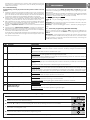 7
7
-
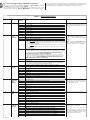 8
8
-
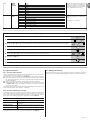 9
9
-
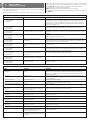 10
10
-
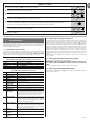 11
11
-
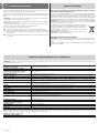 12
12
-
 13
13
-
 14
14
-
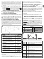 15
15
-
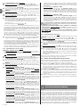 16
16
-
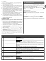 17
17
-
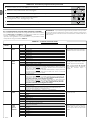 18
18
-
 19
19
-
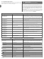 20
20
-
 21
21
-
 22
22
-
 23
23
-
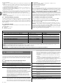 24
24
-
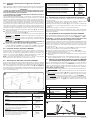 25
25
-
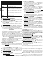 26
26
-
 27
27
-
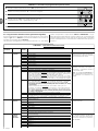 28
28
-
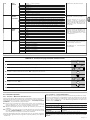 29
29
-
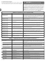 30
30
-
 31
31
-
 32
32
-
 33
33
-
 34
34
-
 35
35
-
 36
36
-
 37
37
-
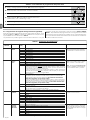 38
38
-
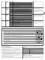 39
39
-
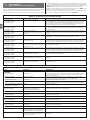 40
40
-
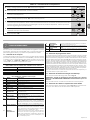 41
41
-
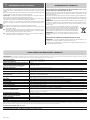 42
42
-
 43
43
-
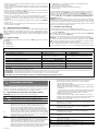 44
44
-
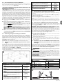 45
45
-
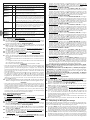 46
46
-
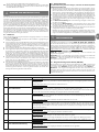 47
47
-
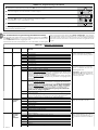 48
48
-
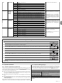 49
49
-
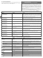 50
50
-
 51
51
-
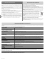 52
52
-
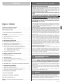 53
53
-
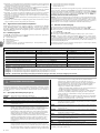 54
54
-
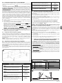 55
55
-
 56
56
-
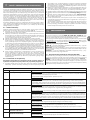 57
57
-
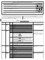 58
58
-
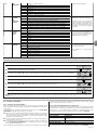 59
59
-
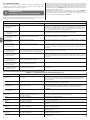 60
60
-
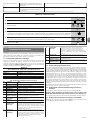 61
61
-
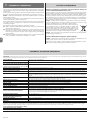 62
62
-
 63
63
-
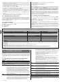 64
64
-
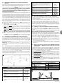 65
65
-
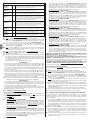 66
66
-
 67
67
-
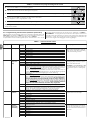 68
68
-
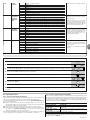 69
69
-
 70
70
-
 71
71
-
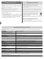 72
72
-
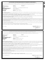 73
73
-
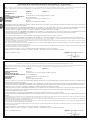 74
74
-
 75
75
-
 76
76
-
 77
77
-
 78
78
-
 79
79
-
 80
80
-
 81
81
-
 82
82
-
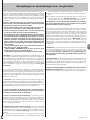 83
83
-
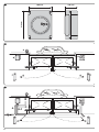 84
84
-
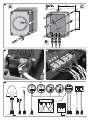 85
85
-
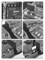 86
86
-
 87
87
-
 88
88


Nice Automation Manual for Moon / Moonclever MC824H Owner's manual
- Type
- Owner's manual
- This manual is also suitable for
Ask a question and I''ll find the answer in the document
Finding information in a document is now easier with AI
in other languages
- italiano: Nice Automation Manual for Moon / Moonclever MC824H Manuale del proprietario
- français: Nice Automation Manual for Moon / Moonclever MC824H Le manuel du propriétaire
- español: Nice Automation Manual for Moon / Moonclever MC824H El manual del propietario
- Deutsch: Nice Automation Manual for Moon / Moonclever MC824H Bedienungsanleitung
- Nederlands: Nice Automation Manual for Moon / Moonclever MC824H de handleiding
- polski: Nice Automation Manual for Moon / Moonclever MC824H Instrukcja obsługi
Related papers
-
Nice Automation Hopp Owner's manual
-
-
-
-
Nice HYKE and HYKE Hi-speed series Owner's manual
-
-
-
Nice OVIEW Owner's manual
-
-
Other documents
-
Marantec Comfort RE2224S Owner's manual
-
-
-
 Mhouse WG2 Owner's manual
-
 Mhouse WG10S K & WG20S Owner's manual
-
 Mhouse WS2S Owner's manual
-
 Mhouse WU2S Owner's manual
-
 Mhouse SL1S and SL10S Owner's manual
-
 NiceHome Maestro 200 Owner's manual
-


