Page is loading ...

VN.M20E VN.M40E
VN.MT20E VN.MT40E
UNIONE NAZIONALE COSTRUTTORI
AUTOMATISMI PER CANCELLI, PORTE
SERRANDE ED AFFINI
L8542845
11/2010 rev4

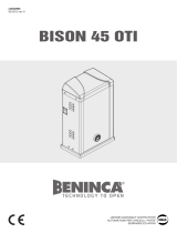
1
433
100
248
211
70
6.4
27.8
70 181
213.5
100
190.5
251
82 min.
150 max.
263
424
15
6
2268
106
263
150 max.
82 min.
424
110
140
433
15
Soffitto.
Ceiling.
Decke.
Plafond.
Techo.
Sufit.
2
3

3
4
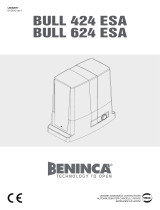
S
C
V
B
A
82 min.
150 max.
263
424
15
6
2268
106
263
150 max.
82 min.
424
110
140
433
15
Parete.
Wall.
Wand.
Cloison.
Pared.
Ściana.
4

5
Z1
d
Z2
6
M
3x1.5 min.
Com.
3
2
STOP
1
F.C.1
F.C.2
Com.
F.C.3
F.C.4
4x1.5 min.
L1 / M
L2 / COM
L3 / M
COM SW
---
GND
SWO
SWC
COM AUX
AUX
a
b
c
d
e
f
g
h
i
l
m
n
o
GND
---
SWO
SWC
COM AUX
---
AUX
L1
L2
L3
---
COM SW
---
GND
---
SWO
SWC
COM AUX
---
AUX
M
COM
M
---
COM SW
---
VN.MT VN.M
, , :
Non utilizzato / Not used / Nicht verwendet / Non utilisé / No utilizado / Nie używany
5

8
Arancio
Rosso+Nero (13)
Blu (16)
Giallo (14/15)
Viola
Nero
Rosso
Nero
Bianco
Rosso
Bianco
Nero
Rosso
Bianco
Bianco
Nero
Nero
Rosso
MM
3
21
Collegamenti a stella per 400V trifase.
Star connection for 400V, three-phase.
Sternverbindung, dreiphasig für 400V.
Connexion étoile pour 400V triphasé.
Conexión estrella para 400V trifásica.
Połączenie gwiazdowe na 400V trójfazowy.
Collegamenti a triangolo per 230V trifase.
Triangle connection for 230V, three-phase.
Dreieckverbindung, dreiphasig für 230V.
Connexion triangle pour 230V triphasé.
Conexión triángulo para 230V trifásica.
Połączenie trójkątowe na 230V trójfazowy.
Centro stella.
Star centre.
Sternmitte.
Centre étoile.
Centro estrella.
Punkt wspólny w połączeniu
gwiazdowym
7
Blu.
Blue.
Blau.
Bleu.
Azul.
Niebieski.
Giallo.
Yellow.
Gelb.
Jaune.
Amarillo.
Żółty.
Arancio.
Orange.
Orange.
Orange.
Naranja.
Pomarańczowy.
Viola.
Violet.
Violett.
Violet.
Violeta.
Fioletowy.
Non utilizzato
Not used.
Nicht verwendet.
Non utilisé.
No utilizado.
Nie używany
Rosso+Nero.
Red+Black.
Rot+Schwarz.
Rouge+Noir.
Rojo+Negro.
Czerwony+Czarny.
Marrone + Bianco
Brown + White
Braun + weiß
Marron + Blanc
Marrón + Blanco
Brązowy + Biały
Arancio
Rosso+Nero (13)
Blu (16)
Giallo (14/15)
Viola
Nero
Rosso
Nero
Bianco
Rosso
Bianco
Nero
Rosso
Bianco
Bianco
Nero
Nero
Rosso
MM
3
21
VN.M VN.MT
Marrone
Brown
Braun
Marron
Marrón
Brązowy
Nero
Black
Schwarz
Noir
Negro
Czarny
6

12
13
8
AUX
SWC
SWC AUX
COM SW
COM AUX.
BrownWhite
Orange
Yellow
Black
Violet
SAFETY SWITCH
Red
Blue
Yellow
Black
AUX
SWC
SWO
SWO SWC AUX
COM SW
COM AUX.
SWO XT
Red Brown
Brown
White
White Blue
SWO
SWO
SWO XT
Red Brown
White Blue
Orange
Yellow
Black
Violet
SAFETY SWITCH
BlackBlack
CIRCUIT BREAKER
Red
Blue
Yellow
Black

The product shall not be used for purposes or in ways
other than those for which the product is intended for and
as described in this manual. Incorrect uses can damage
the product and cause injuries and damages.
The company shall not be deemed responsible for the
non-compliance with a good manufacture technique of
gates as well as for any deformation, which might occur
during use.
Keep this manual for further use.
Qualified personnel, in compliance with regulations in force,
shall install the system.
Packaging must be kept out of reach of children, as it can
be hazardous. For disposal, packaging must be divided
the various types of waste (e.g. carton board, polystyrene)
in compliance with regulations in force.
The installer must supply all information on the automatic,
manual and emergency operation of the automatic system
and supply the end user with instructions for use.
WARNING
•
An omnipolar switch/section switch with remote
contact opening equal to, or higher than 3mm
must be provided on the power supply mains..
Make sure that before wiring an adequate differential
switch and an overcurrent protection is provided.
Pursuant to safety regulations in force, some types of in-
stallation require that the gate connection be earthed.
During installation, maintenance and repair, cut off power
supply before accessing to live parts.
Descriptions and figures in this manual are not binding.
While leaving the essential characteristics of the product
unchanged, the manufacturer reserves the right to modify
the same under the technical, design or commercial point
of view without necessarily update this manual.
EC Declaration of Conformity
Manufacturer: Automatismi Benincà SpA.
Address: Via Capitello, 45 - 36066 Sandrigo (VI) - Italia
Herewith declares that: the operator for hinged gates model
VN.M20E, VN.M40E, VN.MT20E, VN.MT40E
is complying with provisions set forth by the following other EC Directive:
- DIRECTIVE 2004/108/EC OF THE EUROPEAN PARLIAMENT AND OF THE COUNCIL
of 15 December 2004, on the harmonisation of the laws of Member States relating to
electromagnetic compatibility and which cancels Directive 89/336/EEC, according to the
following harmonised regulations: EN 61000-6-2:2005, EN 61000-6-3:2007.
- DIRECTIVE 2006/95/EC OF THE EUROPEAN PARLIAMENT AND OF THE COUNCIL of 12
December 2006, on the harmonisation of the laws of Member States relating to electrical
equipment designed for use with certain voltage limits, according to the following harmonised
regulations: EN 60335-1:2002 + A1:2004 + A11:2004 + A12:2006 + A2:2006 + A13:2008;
EN 60335-1-103:2003.
Benincà Luigi, Legal responsible.
Sandrigo, 10/06/2010.
11

WARNING
• Beforeinstallingtheautomaticsystemreadtheinstructions
hereunder carefully.
• ItisstrictlyforbiddentousetheproductVN.Mforapplications
other than indicated in this instruction handbook.
• Showtheuserhowtousetheautomationsystem.
• Givetheuserthepartoftheleaetwhichcontainstheinstructions
for users.
• AllBenincáproductsarecoveredbyaninsurancepolicyforany
possible damages to objects and persons caused by construc-
tion faults, under condition that the entire system be marked CE
and only Benincá parts be used.
OPERATING LIMITS AND WARNINGS
This geared motor has been studied and manufactured to activate
balanced sectional doors (VN.M20E/VN.MT20E) as well as rolling
doors (VN.M40E/VN.MT40E). Before proceeding to install the sys-
tem, make sure that the door is balanced and slides well. Check
that the ropes, the springs and the parachuting system are in good
conditions. For doors that have not been installed recently, check
also all the other parts subject to wear and tear. The above instruc-
tions are essential for the safety of the system and the reliability
of the operator.
INSTALLATION
Thanks to its versatility, this geared motor can be assembled not
only on the right-side or left-side of the door, but also horizontally
(fig. 2) or vertically (fig. 3). The geared motor has been designed
to directly activate the cable winding shaft of the door which must
feature 1” diameter (25.4mm) and should be provided of housing
for the key. For cable winding shafts having a different diameter,
an adapter should be provided (item VN.A30 for diam. 30 shafts,
item VN.A3175 for diam. 31.75 shafts, item VN.A40 for diam. 40
shafts). To fit the unit proceed as follows (fig.4):
• Check that the distance between the rope coiler shaft “A” and
the surface onto which brackets should be fitted ranges between
82 and 150mm.
• Weldortthebracket“S”tosurfacewithscrews.
• Introducethegearmotorintheropecoilershaft,whileinterposing
the key “C”.
• Tightenthettingscrews“V”.
• Tomounttheplateonside“B”,usescrewsTEM10x20sup-
plied.
To calculate the movement speed of the door, proceed as fol-
lows:
V = d (diam. of cable winding drum - m) x 3.14 x 24 = m/1’
It is possible to use the geared motor by extending the motion to
the rope winding-up shaft by means of a chain (item VN.RM). The
motion can possibly be transmitted reduced or multiplied (item
VN.RV) (fig. 5).
To calculate the movement speed of the door, proceed as fol-
lows:
V = d (diam. of cable winding drum - m) x 3.14 x 24 x Z1 / Z2 = m/1’
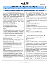
WIRING (fig. 6)
VN.MT20E / VN.MT40E VN.M20E / VN.M40E
GND
Earth. Earth.
Not used. Not used.
SWO
Open limit switch 1x0.5 min. Open limit switch 1x0.5 min.
SWC
Close limit switch 1x0.5 min. Close limit switch 1x0.5 min.
COM AUX
Common of the contact at disposal Common of the contact at disposal
Not used. Not used.
AUX
3A, 24Vdc/ac max. 3A, 24Vdc max.
L1/M
L1 Phase
L2/COM
L2 Com.
L3/M
L3 Phase
Not used. Not used.
COM SW
Common of Limit switch 1x0.5 min. Common of Limit switch 1x0.5 min.
---
Not used. Not used.
VN.M20E/VN.M40E: The 25µF capacitor must be connected to the
motor terminals 7 and 8 of THINK control unit.
To use the micro-switch supplied as a safety limit switch in the
closing phase, modify the cable positions as per fig. 7.
N.B.: Models 400V three-phase can be used also at 230V three-
phase by changing from a star connection to a triangle one as per
fig. 8.
ADJUSTMENT OF THE LIMIT SWITCHES
The geared motor is equipped with 4 microswitches:
Red limit switch Opening limit switch (SWO)
Blue limit switch Opening over-travel (SWO XT)
Yellow limit switch Closing limit switch (SWC)
Black limit switch At disposal of the accessories (AUX)
To adjust the cams proceed as follows:
• Manually move the door until it is almost closed and adjust the
SWC cam until the micro-switch is almost triggered (Fig. 9).
• TightenthedowelshowninFigure10byusinga2.5mmsocket
head key.
• Byusingthesamekey,carryoutthemicrometricadjustmentof
the cam, as shown in Figure 11.
• RepeattheoperationwhileopeningthedoorandadjusttheSWO
cam.
• ThenpositiontheSWOXTcamsothatitisactivatedslightly
delayed with respect to the SWO cam.
• Powertheautomaticunitandoperateit(ifitisaclosingoperation,
invert wires 1 and 3 of the motor power supply, fig. 6 and 7).
• Should further adjustments be required, turn the micrometric
adjustment dowel.
Figure 12 shows the wire diagram of limit switches in single-phase
motors, while Figure 13 shown wire connections in three-phase
motors.
Technical data VN.M20E VN.MT20E VN.M40E VN.MT40E
Power supply
Consumption
Power
Torque
* Door max. weight
Exit shaft hole
Max. force on Ø 120
Exit rounds
** L.S. reduction ratio
Jogging
Thermal switch trig.
Operat. temperature
Capacitor
Lubrication
Weight
Dimensions: see fig.1
1x230V (50Hz)
3A
600W
90Nm
3700N
25.4mm
1500N
24rpm
1/20
40%
130°C
-20°C / +70°C
20µF
Agip Blasia 32
15kg
3x400V (50Hz)
1.7A
800W
105Nm
4800N
25.4mm
1750N
24rpm
1/20
50%
130°C
-20°C / +70°C
Agip Blasia 32
15kg
1x230V (50Hz)
3A
600W
90Nm
3700N
25.4mm
1500N
24rpm
1/40
40%
130°C
-20°C / +70°C
20µF
Agip Blasia 32
15kg
3x400V (50Hz)
1.7A
800W
105Nm
4800N
25.4mm
1750N
24rpm
1/40
50%
130°C
-20°C / +70°C
Agip Blasia 32
15kg
* For balancing doors and diameter Ø 120mm of the steel cable winding drum.
** Max. no. of rounds from the exit shaft.
12

VN.M20E - VN.M40E - VN.MT20E - VN.MT40E
Norme di sicurezza
• Nonsostarenellazonadimovimentodellaporta.
• Nonlasciarecheibambinigiochinoconicomandioinprossimitàdelle
ante.
• Incasodianomaliedifunzionamentonontentarediriparareilguastoma
avvertire un tecnico specializzato.
Manovra manuale e d’emergenza
Nel caso di mancanza dell’energia elettrica o di avaria la manovra manuale
può essere effettuata come segue (fig. 14):
1) Disattivare l'elettrofreno allentando, senza svitare completamente, le due
parti della manopola di sblocco.
2) Tirare entrambe le estremità della catena verso il basso in modo attivare il
meccanismo che consente la movimentazione manuale della porta.
3) Utilizzare la catena per aprire/chiudere la porta. Un microinterruttore di
sicurezza scollega automaticamente il motore durante la manovra manuale.
4) Per ripristinare il funzionamento automatico tirare la cordina con pomello
verde, e riattivare l'elettrofreno riavvitando completamente le due parti della
manopola di sblocco.
Manutenzione
• Controllareperiodicamentel’efcienzadellosbloccomanualediemergen-
za.
• Astenersiassolutamentedaltentativodi effettuare riparazioni,potreste
incorrere in incidenti; per queste operazioni contattare un tecnico specia-
lizzato.
• L’attuatore non richiede manutenzioni ordinarie,tuttavia è necessario
verificare periodicamente l’efficienza dei dispositivi di sicurezza e le altre
parti dell’impianto che potrebbero creare pericoli in seguito ad usura.
Smaltimento
Qualora il prodotto venga posto fuori servizio, è necessario seguire le disposi-
zioni legislative in vigore al momento per quanto riguarda lo smaltimento dif-
ferenziato ed il riciclaggio dei vari componenti (metalli, plastiche, cavi elettrici,
ecc.); è consigliabile contattare il vostro installatore o una ditta specializzata
ed abilitata allo scopo.
Attenzione
Tutti i prodotti Benincà sono coperti da polizza assicurativa che risponde di
eventuali danni a cose o persone causati da difetti di fabbricazione, richiede
però la marcatura CE della ”macchina” e l’utilizzo di componenti originali
Benincà.
Safety rules
• Donotstandinthemovementareaofthedoor.
• Donotletchildrenplaywithcontrolsandnearthedoor.
• Shouldoperatingfaultsoccur,donotattempttorepairthefaultbutcalla
qualified technician.
Manual and emergency operation
In the event of power failure or breakdown, the manual operation can be
carried out as follows (Fig. 14):
1) De-activate the electric brake by backing-off the screws of the two release
knob halves.
2) Pull both chain ends downwards so that the mechanism, which allows the
manual movement of the door, is activated.
3) To open/close the door use the chain. A safety micro-switch cuts-off the
motor automatically during the manual operation.
4) To reset the automatic operating mode, pull the cord with the green knob,
and reset the electric brake by firmly tightening the screws of the two release
knob parts.
Maintenance
• Everymonthcheckthegoodoperationoftheemergencymanualrelease.
• Itismandatorynottocarryoutextraordinarymaintenanceorrepairsas
accidents may be caused.
These operations must be carried out by qualified personnel only.
• Theoperatorismaintenancefreebutitisnecessarytocheckperiodically
if the safety devices and the other components of the automation system
work properly. Wear and tear of some components could cause dangers.
Waste disposal
If the product must be dismantled, it must be disposed according to regula-
tions in force regarding the differentiated waste disposal and the recycling
of components (metals, plastics, electric cables, etc..). For this operation it is
advisable to call your installer or a specialised company.
Warning
All Benincá products are covered by insurance policy for any possible damages
to objects and persons caused by construction faults under condition that the
entire system be marked CE and only Benincá parts be used.
14
ITALIANO
ENGLISH
Libro istruzioni per l’utilizzatore
User’s handbook for the user
Handbuch für den Verbraucher
Manuel d’instructions pour l’utilisateur
Libro de instrucciones para el usuario
Instrukcja obsługi dla użytkownika
1
2
3
4
21

4
2
3
8
6
A
B
C
1
5
7
Pos.
VN.M20E - VN.M40E - VN.MT20E - VN.MT40E
Denominazione - Description - Bezeichnung - Dénomination - Denominación - Określenie
Cod.
1
Albero motore Shaft Welle Arbre moteur Eje motor Wał korbowy
9686850
2
Finecorsa Limit switch Endschalter Fin de course Final de carrera Krańcówka
9686852
3
Albero uscita Output shaft Welle Arbre Eje de salida Wał wyjściowy
9686853
4
Scatola cablag. Cable box Schachtel Boîtiers câbl. Caja cableados Skrzynka okabl.
9686855
5
Carter Cover Abdeckung Carter Tapa Karter
9686856
6
Elettrofreno Electric brake Elektrobremse Electrofrein Electrofreno Hamulec elektryczny
9680091
7
Sblocco elettrof.
Electric brake
release
Entsicherung
Elektrob
Desserrage
électrof.
Desbloqueo
electrofr.
Odblokowanie hamulca
elektryc.
9686092
8
Guida catena Chain guide Führungsketten Guide de châine Guìa cadena Prowadnicy lańc.
9686296
A
Motore VN.ME Motor Motor Moteur Motor Silnik
9686857
Motore VN.MTE Motor Motor Moteur Motor Silnik
9686858
B
Alb. cam. VN.-40E
Cam shaft Nockenwelle Arbre à cames Eje excéntricas Wałek krzywek
9686859
Alb. cam. VN.-20E
Cam shaft Nockenwelle Arbre à cames Eje excéntricas Wałek krzywek
9686860
C
Alb. rinvio VN.-20E
Extens. shaft Rücklaufwelle Arbre de renvoi Eje transmisión Wałek krzywek
9686861
Alb. rinvio VN.-40E
Extens. shaft Rücklaufwelle Arbre de renvoi Eje transmisión Wałek krzywek
9686862
23
/