Installation Instructions
Overview
The CM65 series of room thermostats are 24V
wall-mounted controls. These thermostats
sense room temperature and automatically
close (“ON”) or open (“OFF”) an electric circuit
in the appliance. The Model CM65 thermostat
controls a heating system and is easily con-
verted to control a heating and cooling system
by simply adding the optional SB-6A-5ABO or
SB-6A-5JBO heating/cooling sub-base. The
Model CM65A thermostat is factory-equipped
with either an SB-6A-5ABO sub-base or an SB-
6A-5JBO sub-base.
CM65 and CM65A thermostats have adjust-
able heat anticipators (0.20 to 1.0 amps). A
nonadjustable cooling anticipator (4700 ohms)
is included on the SB-6A sub-base.
The CM65 thermostat includes a cover and a
mounting body. The CM65A thermostat in-
cludes a cover, mounting body, and heating/
cooling sub-base. A manual temperature-
setting lever and Fahrenheit/Celsius tempera-
ture scales are provided. Precise leveling is
not required.
Specifications
Wiring must conform to local codes and ordi-
nances for Class II low-voltage circuits. Other
specifications are as follows:
• Class II circuit (30VAC, 1.0 amps maxi-
mum): 24V nominal (four or five-wire circuit
required for optional air conditioning)
Model CM65 Series
24 Volt Convertible Heating Thermostat/24 Volt Heating/Cooling Thermostat with Sub-base
Room Thermostats
• Sensor: Bi-metal coil with dust-protected
open-contact switches
• Anticipator
- Heating: 0.20-1.0 amps; adjustable
- Cooling: 4700 ohms; fixed resistor
• Temperature range: 50°F to 90°F; 10°C to
30°C
• Temperature differential: 2°F; 1°C
• Size: 3” x 3-1/2” x 1-1/2” (76m x 89mm x
38mm)
!
WARNING:
This is a precision instrument. Handle
carefully. Only the procedures out-
lined in this bulletin are approved by
the manufacturer. Replace thermo-
stat if other service is required.
!
WARNING:
Always disconnect electricity to the
appliance before installation or ser-
vice.
CM65A Heating/Cooling Thermostat
with Sub-base
CM65 Convertible

2
Location
Temperature-sensing controls are sensitive to
surrounding temperature and should not be
exposed to unusual temperature conditions or
poor air circulation. Carefully consider the
following location factors before installing the
thermostat.
Locate Thermostat:
• In an area easily accessible to wiring, ser-
vice, and adjustment
• In a frequently used room, such as a living
room or family room.
• On an inside wall about four or five feet
above the floor.
Do Not Locate Thermostat:
• In an area of unusual heating conditions,
such as in direct sunlight or near heat pro-
ducing sources (lamps, TV sets, radiators,
heat registers, etc.).
• In a humid area. Humidity reduces its life
expectancy.
• In an area of unusual cooling conditions,
such as on an outside wall (or one separat-
ing an unheated room) or in drafts from
stairwells, doors, windows, etc.
• Where air circulation is poor, such as behind
normally open doors or room dividers, in
corners or alcoves, over or near large furni-
ture.
• On a wall subject to frequent vibration, such
as near frequently used doors.
INSTALLING MODEL CM65
1. Disconnect electrical power to appliance.
2. Grip thermostat cover at top and bottom.
Remove cover from thermostat body.
3. Hold thermostat body level and against
wall. With a pencil, mark wall where
screws will attach thermostat body to wall.
NOTE: Use designated mounting holes
only (see Figure 1).
4. Lay thermostat body to one side. Drill
mounting holes with 3/32" drill bit.
5. Pull three inches of five-conductor wire
through wall opening and strip 3/8" at
ends.
NOTE: Tape ends of three wires for future
installation of optional heating/cooling sub-
base.
6. Connect wires to screw terminals (see
Figure 2) and tighten securely. Bend wires
to prevent possible interference with tem-
perature selector.
7. Push wires back through wall opening,
leaving some slack. Close wall opening
with noncombustible insulating material.
8. Mount thermostat body to wall with screws.
(Precise leveling is not required.)
9. Replace thermostat cover.
10. Check low-voltage (24V) circuit(s) to ap-
pliance and make appropriate wiring con-
nections (see Figure 4). Also refer to
wiring diagram on appliance.
11. Restore electrical power to appliance.
INSTALLING MODEL CM65A OR
ADDING OPTIONAL SB-6A-5ABO
OR SB-6A-5JBO HEAT/COOL
SUB-BASE TO MODEL CM65
1. Disconnect electrical power to appliance.
2. Grip thermostat cover at top and bottom
and remove from thermostat body.
3. Remove mounting screws and pull ther-
mostat body (CM65) away from wall. Dis-
connect low-voltage wires from screw ter-
minals.
4. Unwrap taped wires.
NOTE: If five-conductor circuit was not
previously provided, install additional wires
as needed and strip ends 3/8".
5. Insert wires through wire entry of sub-base
(see Figure 3) and connect to respective
screw terminals. Tighten all screws se-
curely.
NOTE: Add or remove red jumper be-
tween RH and RC as needed. See Figures
6, 7, 10, 11, 12 and 13.
6. Push wires back through wall opening,
leaving some slack. Close wall opening
with noncombustible insulating material.
7. Mount sub-base to wall with screws. (Pre-
cise leveling is not required.)
8. Mount thermostat body to sub-base. Se-
cure by tightening captive screws (see
Figure 1).
9. Replace thermostat cover.
10. Check low-voltage (24V) circuit(s) to
appliance(s) and make appropriate wiring
connections (see Figure 5,6,7, or 8). Also
refer to wiring diagram on appliance(s).
11. Restore electrical power to furnace.

3
RH
W
B
RC
G
HEAT COOL
ON
OFF
AUTO
VENTILATE
O
Y
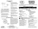
Mounting
Hole
Wire Entry
2 1/4"
57 mm
Jumper
between
RC & RH
for single
transformer
systems
(SB-6A-5JBO
only)
Cooling
Anticipator
Heat/Cool
Switch
1 5/8"
41 mm
Mounting
Hole
Fan
Switch
Figure 1. T’stat Body/Front View
Figure 2. T’stat Body/Rear View
Figure 3. T’stat Sub-base/Front View
2
3
4
5
7
10
Temperature
Selector
Contacts
Captive
Screw
Point "A"
Magnets
Mounting
Hole
Cover Guide
Adjustable
Heat Anticipator
Indicator
Mounting
Hole
Captive
Screws
Point "B"
Bimetal
Coil
R
Y
W
Temperature
Selector
Terminal
W
Mounting
Hole
Mounting
Hole
Terminal
R
2 1/4"
57 mm
1 5/8"
41 mm

4
SEQUENCE OF OPERATION
!
CAUTION:
Do not short control terminals at ap-
pliance to test system. Room ther-
mostat will be damaged and warranty
will be VOIDED.
NOTE: If appliance(s) is equipped with time
delay control, the system operation will lag
behind the thermostat.
For Heating
1. Turn on electrical power to appliance.
2. With thermostat cover off, move tempera-
ture-setting lever until right-hand (heat-
ing) contacts close. For CM65A-5ABO,
CM65A-5JBO or CM65 with optional sub-
base, set heat/cool switch to “HEAT” and
set ventilate switch to “AUTO.” Heating
system and air circulator blower should
turn on.
3. Check air temperature at supply duct regis-
ters.
4. Move temperature-setting lever until right-
hand (heating) contacts open. Heating
system and air circulator blower should
turn off.
5. Replace thermostat cover.
For Cooling
1. Turn on electrical power to the appliance.
2. With the thermostat cover off, move tem-
perature-setting lever until left-hand (cool-
ing) contacts close. For CM65A-5ABO,
CM65A-5JBO or CM65 with optional sub-
base, set heat/cool switch to “COOL” and
set ventilate switch to “AUTO.” Cooling
system and air circulator blower should turn
on.
3. Check air temperature at supply duct regis-
ters.
4. Move temperature-setting lever until left-
hand (cooling) contacts open. Cooling sys-
tem and air circulator blower should turn
off.
5. Replace thermostat cover.
For Continuous Air Circulation
and Ventilation
NOTE: For CM65, see furnace owner’s manual
on independent blower operation. For CM65A-
5ABO, CM65A-5JBO or CM65 with optional
sub-base, follow the steps below.
1. Set thermostat heat/cool switch to “OFF”
and set ventilate switch to “ON.” Air circu-
lator blower only should turn on.
2. Set thermostat heat/cool switch to “HEAT.”
Air circulator blower should operate con-
tinuously with on and off heat cycles.
3. Set thermostat heat/cool switch to “COOL.”
Air circulator blower should operate con-
tinuously with on and off cooling cycles.
For System Shutoff
1. With electrical power to appliance turned
on, move temperature-setting lever to turn
on heating or cooling system.
2. Set ventilate switch to “AUTO” and set
heat/cool switch to “OFF.” All system
operations should turn off.

5
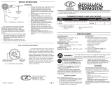
Figure 4. CM65 (Heating Only) No Sub-base
Figure 5. Sub-base SB-6A-5ABO Two Transformers
* For Sub-base SB-6A-5ABO Only: for Single
Transformer, add Jumper (provided on back of sub-
base) as shown.
** For Sub-base SB-6A-5JBO Only: for two
transformers, remove jumper wire (see Figure 3) for
independent circuit operation.
NOTE: A suitable Limit Control is required in the
Low-Voltage or line-Voltage side of the transformer.
All RC and RH terminals were previously R and A
respectively.
Legend:
CA - Cooling Anticipator
CR - Cooling Relay
FR - Fan Relay
FS - Fan Switch
HA - Heating Anticipator
HC - Heating Control
J - Jumper Wire
LS - Limit Switch
RC - Cooling Transformer
RH - Heating Transformer
TB - Thermostat Base
TR - Transformer

6
Figure 6. Sub-base SB-6A-5ABO Single Transformer
Figure 7. Sub-base SB-6A-5JBO Two Transformers
Figure 8. Sub-base SB-6A-5JBO Single Transformer

7
Figure 9. Heating Only
Figure 10. Sub-base SB-6A-5ABO or
SB-6A-5JBO Single Transformer
Self-contained A/C with integral Heater
Figure 12. Sub-base SB-6A-5ABO or SB-6A-5JBO Two Transformers,
Split-system A/C with Furnace
Figure 11. Sub-base SB-6A-5ABO or SB-6A-5JBO Two Transformers
Self-contained A/C and Furnace

707756A (Replaces 7077560)
Specifications and illustrations subject to change without notice and
without incurring obligations. Printed in U.S.A. (07/99)
Robertshaw #87548
R
R
INSTALLER: Do Not Discard These Instructions. After completing the installation,
return these instructions to the Homeowner’s Package for owner-user’s future
reference. Complies with H.U.D. Manufactured Home Construction &
Safety Standards.
¢707756J¤
707756A
Figure 13.
Sub-base SB-6A-5ABO or SB-6A-5JBO Single Transformer, Split-system A/C with Furnace
/