Page is loading ...

User Manual
875 Bassett Rd.
Westlake Ohio 44145 USA
(800) 817-7890
WesternEnterprises.com
Meriam.com
HPT100 Hydro/Pneumatic Tester
© Western Enterprises 2021

9R737-A ECN-18757 (2103)
2
Contents
Table of Contents
Contents
...................................................................................................................................................... 2
General Information
................................................................................................................................. 6
Notification Statements
.................................................................................................................... 6
Disclaimer
.............................................................................................................................................................. 6
Copyright
............................................................................................................................................................... 6
Trademark information
.................................................................................................................................. 6
Warranty
............................................................................................................................................... 7
General Warnings and Cautions
.......................................................................................................... 8
Preventing injury
................................................................................................................................ 8
Safety symbols
.................................................................................................................................... 8
For your safety
.................................................................................................................................... 9
Fire and explosion hazard
............................................................................................................................ 9
Pressure limits
.................................................................................................................................................... 9
Protect the Hydro/Pneumatic Tester
.................................................................................................... 9
Prevent trip hazards
........................................................................................................................................ 9
Perform these checks each time
.................................................................................................... 9
Hydro/Pneumatic Tester
....................................................................................................................... 11
Features of the Hydro/Pneumatic Tester
................................................................................... 11
HPT100 Hydro/Pneumatic Tester:
......................................................................................................... 11
Hose and Cables:
............................................................................................................................................. 11
Fittings, Probes, & Terminals:
................................................................................................................... 11
Battery Kit
............................................................................................................................................................. 11
Storage Cases
.................................................................................................................................................... 11
Serial number
..................................................................................................................................................... 11
Sensors
................................................................................................................................................................. 12
Sensor manifold types
.................................................................................................................................. 12
No serviceable customer parts
............................................................................................................... 12
Accessory specifications
................................................................................................................. 12
RTD temperature probe type
.................................................................................................................... 12
RTD temperature probe limits
................................................................................................................. 12
RTD temperature probe accuracy
......................................................................................................... 12
Pressure hose type
......................................................................................................................................... 12
Pressure hoses limits
.................................................................................................................................... 13
Stroke Counter fly wires
.............................................................................................................................. 13
Stroke Switch
.................................................................................................................................................... 13

9R737-A ECN-18757 (2103)
3
Battery (P/N: Z9P1956)
................................................................................................................................ 13
Battery Charger
................................................................................................................................................ 13
Battery Cable
..................................................................................................................................................... 13
Connecting to Power
.............................................................................................................................. 14
Connect pipe under test to a Hydro/Pneumatic Tester
............................................................... 16
Power up Hydro/Pneumatic Tester
.................................................................................................... 17
Application
................................................................................................................................................. 18
Control Selection
.................................................................................................................................18
Main Screen
........................................................................................................................................18
Three modes in the application
..................................................................................................... 21
Setup mode
........................................................................................................................................ 22
Overview of Setup mode
............................................................................................................................ 22
Test information in Setup mode
............................................................................................................ 23
Elevation in Setup mode
............................................................................................................................ 37
Information Data Format
........................................................................................................................... 39
Pressure Measurement in Setup mode
............................................................................................. 40
Temperature Measurement in Setup mode
..................................................................................... 41
Pump Monitoring in Test mode
............................................................................................................. 42
Data Displays in Setup Mode
.................................................................................................................. 43
Notes in Setup mode
................................................................................................................................... 44
Record Button in Setup Mode
................................................................................................................ 44
Test mode
........................................................................................................................................... 45
Overview of Test mode
............................................................................................................................... 45
Test information in Test mode
................................................................................................................ 47
Elevation in Test mode
................................................................................................................................ 47
Pressure Measurement in Test mode
................................................................................................ 48
Temperature Measurement in Test mode
....................................................................................... 48
Pump Monitoring in Test mode
............................................................................................................. 48
Data Displays in Test Mode
..................................................................................................................... 49
Notes in Test mode
....................................................................................................................................... 53
Stopwatch button in Test mode
............................................................................................................ 53
Stop Button in Test mode
.......................................................................................................................... 54
Review mode
...................................................................................................................................... 55
Overview of Review mode
......................................................................................................................... 55
Test information in Review mode
......................................................................................................... 56
Elevation in Review mode
......................................................................................................................... 56
Pressure Measurement in Review mode
.......................................................................................... 57
Temperature Measurement in Review mode
................................................................................. 57
Pump Monitoring in Review mode
....................................................................................................... 57
Data Displays in Review Mode
............................................................................................................... 57
Notes in Review mode
................................................................................................................................. 61
Return Button in Review mode
............................................................................................................... 61
Application update rates
................................................................................................................ 62

9R737-A ECN-18757 (2103)
4
Settings
............................................................................................................................................... 63
Menu button
....................................................................................................................................... 65
Open prior test data
...................................................................................................................................... 66
Transfer files
...................................................................................................................................................... 67
Power Off
............................................................................................................................................................ 68
Specifications
.......................................................................................................................................... 69
Power Requirements
....................................................................................................................... 69
Wall adaptor
...................................................................................................................................................... 69
Battery Charger
............................................................................................................................................... 69
Battery
.................................................................................................................................................................. 69
Hydro/Pneumatic Tester device
............................................................................................................ 69
Pressure measurement
................................................................................................................... 69
Pressure sensor limits
................................................................................................................................. 69
Pressure sensor accuracy
......................................................................................................................... 69
Pressure sensor type
.................................................................................................................................... 69
Temperature measurement
........................................................................................................... 69
RTD temperature probe
.............................................................................................................................. 69
Temperature sensor and probe accuracy
........................................................................................ 70
Environmental range
....................................................................................................................... 70
Display
................................................................................................................................................. 70
Materials
............................................................................................................................................. 70
Certifications
..................................................................................................................................... 70
Dimensions
........................................................................................................................................ 70
Weight
................................................................................................................................................. 70
Warm up time
.................................................................................................................................... 70
Maintenance and cleaning
.................................................................................................................... 71
Don’t void your warranty
................................................................................................................. 71
Cleaning
............................................................................................................................................... 71
Recommended maintenance
......................................................................................................... 71
Prepare for storage
........................................................................................................................... 71
Recycling compliance
...................................................................................................................... 71
Replacement Parts
........................................................................................................................... 72
Troubleshooting
...................................................................................................................................... 73
Temperature measurements display ??????
............................................................................ 73
No measurements in the graph
.................................................................................................... 73
The application didn’t start automatically
................................................................................. 73
The battery loses charge
................................................................................................................ 73
Help
............................................................................................................................................................. 74
Register your product
..................................................................................................................... 74
Find downloads and documents
.................................................................................................. 74
Returning for repair or calibration
............................................................................................... 75
First ― Request a number
......................................................................................................................... 75

9R737-A ECN-18757 (2103)
5
Return Material Authorization
................................................................................................................. 75
Questions? Call Western Enterprises
................................................................................................. 76
Ship the box to
................................................................................................................................................. 76
Western Contact Information
............................................................................................................. 76
Address
................................................................................................................................................................ 76
Telephone
........................................................................................................................................................... 76
Fax
........................................................................................................................................................................... 76
E-mail addresses
............................................................................................................................................ 76
Websites
.............................................................................................................................................................. 76
Find a local Meriam representative
..................................................................................................... 76

9R737-A ECN-18757 (2103)
6
General Information
Notification Statements
Disclaimer
Hydro/Pneumatic Tester is a diagnostic instrument for measuring
temperature, pressure, & number of pump strokes for pipeline
tests. The Hydro/Pneumatic Tester does not assess successful
completion of pipeline tests.
Every precaution has been taken in the preparation of this
manual. Nevertheless, Western Enterprises assumes no
responsibility for errors or omissions or any damages resulting
from the use of the information contained in this publication,
including, without limitation, incidental, special, direct or
consequential damages. Western Enterprises MAKES NO
REPRESENTATIONS OR WARRANTIES WITH RESPECT TO THE
ACCURACY OR COMPLETENESS OF THE CONTENTS HEREOF
AND SPECIFICALLY DISCLAIMS ANY IMPLIED WARRANTIES
OF MERCHANTABILITY OR FITNESS FOR ANY PARTICULAR
PURPOSE.
Western Enterprises reserves the right to revise this publication
and to make changes from time to time in the content hereof
without obligation to notify any person of such revision or
changes.
In no event shall Western Enterprises be liable for any indirect,
special, incidental, consequential, or punitive damages or for
any lost profits arising out of or relating to any services provided
by Western Enterprises or its affiliates.
It is not possible for Western Enterprises to identify all
foreseeable uses or misuses, therefore all persons involved in
commissioning, using, or maintaining this product must satisfy
their self that each intended application is acceptable.
The intended product service life is 10 years.
Copyright
This publication is proprietary to Western Enterprises and no
ownership rights are transferred. Neither this manual, nor any of
the material contained herein, may be reproduced without the
prior written consent of Western Enterprises.
Trademark information
Trademark statement
All other trademarks are the property of their respective owners.

9R737-A ECN-18757 (2103)
7
Warranty
Components of this system are warranted under use against any
and all manufacturing defects from the listed date of manufacture
for one (1) year.
Any failure resulting from defective parts or faulty workmanship,
as determined during evaluation by the manufacturer, will be
repaired under warranty. This warranty will be null and void for any
unit that has been subject to misuse, negligence, accident,
or repairs other than those performed by Western Enterprises or
an approved affiliate.

9R737-A ECN-18757 (2103)
8
General Warnings and Cautions
Preventing injury
Failure to follow all instructions could result in injury:
▪
Read the entire manual before using the Hydro/Pneumatic Tester.
▪
Understand the contents before using the Hydro/Pneumatic Tester.
▪
Follow all safety warnings and instructions provided with this
product.
Safety symbols
The following table defines the safety symbols, signal words,
and corresponding safety messages used in the manual. These
symbols:
▪
Identify potential hazards.
▪
Warn you about hazards that could result in personal injury or
equipment damage.
Safety symbols
Explaining the symbols

9R737-A ECN-18757 (2103)
9
For your safety
Fire and explosion hazard
▪
Never use the Hydro/Pneumatic Tester in hazardous areas.
▪
Don’t open the Hydro/Pneumatic Tester housing. There are
no customer serviceable components inside. Opening the
housing voids the warranty.
▪
Substitution of components may impair operation and safety.
Pressure limits
▪
Don’t exceed the sensor limit.
▪
Full Scale calibrated range = 110 % of range.
▪
Failure to operate within the specified pressure limits
could result in death or serious injury.
Protect the Hydro/Pneumatic Tester
▪
Protect the Hydro/Pneumatic Tester from water or liquid spills.
Prevent trip hazards
1.
Don’t suspend any hose, cable, or input connections from the
device.
2.
Watch out for hoses, cables, or power cords when you set up
device connections.
Perform these checks each time
1.
Check the specified pressure and temperature connection
types and rating ranges for accessories.
2.
Only use third party accessories if they match the
connection types and/or ratings of the device sensors.
3.
Examine the power cord and adapter to make certain they are
not damaged.
4.
Place the device on a flat, stable surface before connecting
cables or hoses.
5.
Check the pressure hoses to make certain they have no
cracks, holes, defects, or unusual wear and tear.
!
DANGER
!
WARNING
!
CAUTION
!
CAUTION

9R737-A ECN-18757 (2103)
10
6.
Look for cracks, residue, or other damage around the sensor
ports. If you see any,
don’t use the device
. Contact the
appropriate personnel.
7.
Check all input, hose, and cable connections to make sure
they are correctly and securely attached.
8.
Check the computer screen to make sure it is not cracked or
damaged.
1.
Don’t let sharp or hard objects touch the screen.
NOTICE

9R737-A ECN-18757 (2103)
11
Hydro/Pneumatic Tester
Features of the Hydro/Pneumatic Tester
The Hydro/Pneumatic tester kit includes:
HPT100 Hydro/Pneumatic Tester:
▪
10.2 in. touchscreen computer
▪
Three RTD temperature sensors
▪
One Compound Isolated 3000 psi pressure sensor
▪
One pump stroke counter
▪
Wireless keyboard and mouse
▪
AC adaptor
Hose and Cables:
▪
One 150 ft. (45 m) pressure hose on reel
▪
Four 150 ft. (45 m) 4 pin M12 A coded cables on reels
▪
Three 9.9 ft. (3 m) 4 pin M12 A coded armored cable
▪
One 3.3 ft. (1 m) Stroke Counter fly wire lead to 4 pin M12 A coded
cable
Fittings, Probes, & Terminals:
▪
Two 1/8” NPT to Quick Test fittings
▪
Two 1/4” NPT to Quick Test fittings
▪
Three class A RTD M12 A coded probes
▪
One electrical terminal kit
Battery Kit
▪
12V, 18 Ah sealed lead acid battery
▪
5A battery charger
▪
Battery power cable
Storage Cases
▪
One soft sided case
▪
One hard sided case
Serial number
The serial number is located on the bottom of the Hydro/Pneumatic
Tester.

9R737-A ECN-18757 (2103)
12
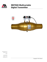
Sensors
Use two wrenches to install or remove the pressure connection
Connection: 1/8 in. female NPT, 316LSS.
▪
Use PTFE tape for NPT fittings.
▪
Always use a 3/4 in. wrench on the pressure manifold when you
install or remove the 1/8 in. NPT fitting.
▪
Applying torque to the manifold can damage the enclosure and
voids the warranty.
▪
Don’t over tighten.
Sensor manifold types
No serviceable customer parts
If you open the Hydro/Pneumatic Tester, you void the warranty.
Accessory specifications
RTD temperature probe type
▪
PT100 Class A, 4-Wire Platinum RTD
Elements per IEC 60751 Standard
▪
4 Pin M12 A coded connection
RTD temperature probe limits
▪
Functional measurement range: -50 °C to 250 °C
RTD temperature probe accuracy
▪
Tolerance: ± (0.15 + 0.002[t])°C
Pressure hose type
NOTICE
CI3000
RTD
Stroke Counter

9R737-A ECN-18757 (2103)
13
▪
Connection material: Stainless Steel
▪
Collar Material: Stainless Steel
▪
Hose core material: Stainless Steel
▪
Connection 1: Female Quick-test
▪
Connection 2: Female Quick-test
Pressure hoses limits
▪
Maximum allowable working pressure is 6900 psi at 140 °F.
▪
Rated temperature range: -40 °F to 450 °F.
Stroke Counter fly wires
▪
4 Pin M12 A coded male connection
Stroke Switch
▪
“Dry” contact
▪
Single Pole, Single throw
Battery
(P/N: Z9P1956)
▪
12V dc
▪
18 Ah
▪
Provides a run time of approximately 20 hours on a single charge
Battery Charger
▪
Input;
▪
100 – 240 V ac 50/60 Hz
▪
Output
▪
12 V dc
▪
5 A dc
Battery Cable
▪
Positive Connection protected by 5A fuse
▪
Fuse Type: Glass 5A 5X20MM

9R737-A ECN-18757 (2103)
14
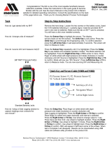
Connecting to Power
There are three options for connecting the power for the HPT100.
All of the accessories required to connect any of the options are
included with the device. Connect the selected option to the
device using the marked power port.
▪
Option 1: AC/DC power adapter
•
When AC power is reliably available.
▪
Option 2: Battery & Battery Charger
•
Use as an uninterruptable power supply for critical
testing when AC power is available.
+

9R737-A ECN-18757 (2103)
15
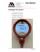
▪
Option 3: Battery
•
The provided battery will power the HPT100 for
approximately 18 hours from a full charge.
•
Use a voltmeter (not included) to check the voltage
level of the battery.

9R737-A ECN-18757 (2103)
16
Connect pipe under test to a
Hydro/Pneumatic Tester
The method of connecting the Hydro/Pneumatic Tester may differ
from device to device. The Hydro/Pneumatic Tester is designed to
give the operator maximum flexibility during test set up.
Customers can choose to use the included accessories or use
their own vendors to purchase hoses, cables, RTD probes, etc. to
meet their requirements.
1.
Inspect the Hydro/Pneumatic Tester, cables, hose, probes,
fittings, etc. prior to use.
2.
Apply power to the Hydro/Pneumatic Tester and turn the
device on.
3.
Install the RTD probes into their required locations (pipe under
test, fill dirt, ambient, etc.). A thermowell (not included) may be
required for pipe installation.
4.
Connect the RTD probes to the Hydro/Pneumatic Tester using
the 150 ft. M12 cables.
Note: If the cables require extra protection near the
RTD probe end, use the 9.9 ft. armored cables
between the 150 ft. cables and the RTD probes.
5.
Install required pressure fittings into the pipe under test.
Use
PFTE tape for NPT fittings.
Note:
A valve may need to be installed to allow the
pressure system to be vented for the purposes
of zeroing the sensor or disconnecting the
equipment.
6.
Install pressure fitting into the Hydro/Pneumatic Tester.
Use
PFTE tape for NPT fittings.
7.
Connect the pressure hose between the pipe fitting and the
Hydro/Pneumatic Tester fitting.
Note: Before connecting the pressure sensor hose to
the HPT100, turn the power on and make sure to
zero the pressure sensor prior to completing the
hook up.
8.
If required, install the stroke counter fly wire adapter to the
pump using the terminal kit.
9.
If required, connect a 150 ft. M12 cable between the stroke
counter fly wire cable and the Hydro/Pneumatic Tester.

9R737-A ECN-18757 (2103)
17
Power up Hydro/Pneumatic Tester
▪
Connect the Hydro/Pneumatic tester to power source per
above section “Connecting to power”.
▪
Press the power button located on the front of the
Hydro/Pneumatic Tester.
▪
The Hydro/Pneumatic Tester will go through a boot up
sequence (< 1 min) and then go directly into setup mode.

9R737-A ECN-18757 (2103)
18
Application
Control Selection
The following options are available to interact with the device:
1.
Tap the touch screen to select a control.
2.
Select a control by clicking it with the mouse
3.
Use the keyboard to enter data.
Note: Keyboard and mouse dongle are located in the mouse
battery compartment and plugs into the USB connection on the
unit.
Main Screen
Once the Hydro/Pneumatic Tester boot sequence completes, the
application loads to the Main screen. The user interacts with
different controls on this screen to set up, run and review test
data.
Measurement controls
▪
Five controls at the top of the screen display measurements.
▪
Different colors are used to distinguish the five sensors.
▪
Tap each control to make changes to the sensor settings.

9R737-A ECN-18757 (2103)
19
Information button
▪
Pressing this button brings up the test information screens to
enter test specific information.
▪
Test information is visible in the information window on the
main screen.
Elevation button
▪
Active for hydrostatic tests only.
▪
Tapping this button brings up the information page to
calculate pressures in the pipe due to change in pipe
elevation.
Elapsed time
▪
Indicates the total time of data collection.
Testing time
▪
Indicates the accumulated time of a test period.
Remaining time
▪
Indicates the time remaining during a test period.
Start/Stop/Return Button
▪
Control to start and stop a data log.
▪
Control to return to set up from a data log review.
▪
Button changes function based on mode.
Status Bar
▪
Messages (such as alarms) to the user are displayed here.
▪
Status circle
•
Solid
Gray
means no data logging.
•
Blinking
Green
means data logging is recording
data.
•
Solid
Red
means Hydro/Pneumatic Tester is locked
while you review the log reports.
Note: The Menu, Setting, time adjustment, and indicator
buttons are unavailable when the status circle is flashing green
or red.
Menu Button
▪
Open prior tests for review.
▪
Transfer test files to a USB stick.
▪
Power down the HPT100.
Clock & Calendar

9R737-A ECN-18757 (2103)
20
▪
Displays the current date and time
▪
Set the date and time
Settings Button
▪
Open settings page to manage the device.
/