
EN
MODULAR CHILLERS
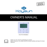
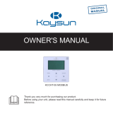
USER MANUAL
KJRM-120H2
WIRED CONTROLLER


● This manual gives detailed description of the precautions that
should be brought to your attention during operation.
● In order to ensure correct service of the wire controller please read
this manual carefully before using the unit.
● For convenience of future reference, keep this manual after reading
it.

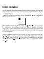
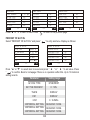
Restore initialization
If the user accidentally sets the display language of the wire controller to a language that the user does
not know, the following three steps can be used to restore the wire controller to the factory setting and
reset the display language:
1)Power off the wireline controller and power it on again. Press and hold + + to enter the
following page within 60 seconds.
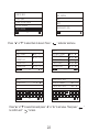
2)Press the buttons from left to right, from top to bottom, click ->▲ -> ->... Turn on 1, 2, 3, 4, 5,
6, 7, 8 and 9, wait for 100% initialization, and enter the FCT page. After entering the FCT page, the
version number is displayed. All set parameters of the equipment are reset to the default parameters, and
saved. The timing settings and fault records are cleared. The equipment returns to the factory state. (exit
FCT after power on again).
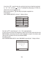
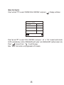
3)Power off the wireline controller and power it on again. The display language will be reset. Press
" "" "" " " " to select the language of the remote controller. After the language setting is completed,
click " ", select "YES", and then click " " to enter the SETTING ADDRESS interface. After setting
SETTING ADDRESS, click" " to enter GENERAL SETTING. Then after setting GENERAL SETTING,
click " ".

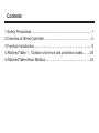
Contents
1 Safety Precautions ...........................................................................1
2 Overview of Wired Controller ...........................................................3
3 Function Introduction........................................................................8
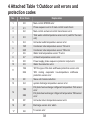
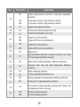
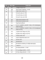
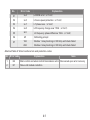
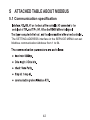
4 Attached Table 1Outdoor unit errors and protection codes .........38
5 Attached Table About Modbus ........................................................42
Restore initialization
If the user accidentally sets the display language of the wire controller to a language that the user does
not know, the following three steps can be used to restore the wire controller to the factory setting and
reset the display language:
1)Power off the wireline controller and power it on again. Press and hold + + to enter the
following page within 60 seconds.
2)Press the buttons from left to right, from top to bottom, click ->▲ -> ->... Turn on 1, 2, 3, 4, 5,
6, 7, 8 and 9, wait for 100% initialization, and enter the FCT page. After entering the FCT page, the
version number is displayed. All set parameters of the equipment are reset to the default parameters, and
saved. The timing settings and fault records are cleared. The equipment returns to the factory state. (exit
FCT after power on again).
3)Power off the wireline controller and power it on again. The display language will be reset. Press
" "" "" " " " to select the language of the remote controller. After the language setting is completed,
click " ", select "YES", and then click " " to enter the SETTING ADDRESS interface. After setting
SETTING ADDRESS, click" " to enter GENERAL SETTING. Then after setting GENERAL SETTING,
click " ".

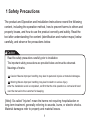
The product and Operation and Installation Instructions record the following
content, including the operation method, how to prevent harms to others and
property losses, and how to use the product correctly and safely. Read the
text after understanding the content (identification and marker maps) below
carefully, and observe the precautions below.
[Note]: So-called "injuries" mean the harms not requiring hospitalization or
long-term treatment, generally referring to wounds, burns, or electric shocks.
Material damages refer to property and material losses.
!
Caution
!
Warning
!
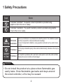
1 Safety Precautions
Caution
Read the safety precautions carefully prior to installation.
The important safety precautions are provided below and must be observed.
Meanings of marks:
Means improper handling may lead to personal injuries or material damages.
Means improper handling may lead to death or serious injury.
After the installation work is completed, confirm that the trial operation is normal and hand
over the manual to the customer for keeping.
1

It indicates "prohibited". The specific content of prohibition is provided using
graphics or text in the icon or nearby.
It indicates "mandatory". The specific mandatory content is provided using graphics
or text in the icon or nearby.
Icon
Name
Do not spray combustible spray to the wired controller directly; otherwise a fire may be
caused.
Do not perform operations with a wet hand or allow water to enter the wired controller;
otherwise the wired controller will be damaged.
Prohibited
Prohibited
Caution
in Use
Entrust your distributor or a professional to install the product. The installation operator
must have acquired the relevant professional knowledge.
In case of independent installation, wrong operations will lead to a fire, electric shock,
or injury.
Entrusted
installation
Warning
!
Do not install the product at a place where flammable gas
easily leaks. Once flammable gas leaks and stays around
the wired controller, a fire may be caused.
!
1 Safety Precautions
Caution
2

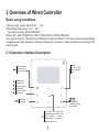
2 Overview of Wired Controller
3
Basic using conditions:
1)Power range: power input: AC 8V 12V;
2)Operating temperature: -2060;
Operating humidity: RH40%~RH90%;
Where: HP—HEAT PUMP;CO—ONLY COOLING;FC—FREE COOLING.
It’s a general manual. The functions of different models are different. The wired controller automatically
recognizes and hides irrelevant interfaces. Please set and inquire related parameters according to the
outunit model.
2.1 Operation Interface Description
Turn on or off the
space operation
mode
Enter the menu
structure from
the home page
Navigate the
cursor on the
display/navigate
in the menu
structure/ adjust
the settings
Come back to
the up level Long press for
unlocking /locking
the controller
Go to the next step when
programming a schedule in the
menu structure / confirm a
selection/enter a submenu in
the menu structure

4
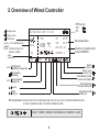
2 Overview of Wired Controller
12/04/2019 MON 10:35A
HEAT
ON
45% 60%
TWTWS
TSF
ONLINE 16
ERRORE 1
40
C
60 50
7
C
C
HP:No icon
CO:
FC:
Units
operating
Heating mode
Cooling mode
DHW mode
COOLFC:COMP/MIX/FC
/HEAT/
DHWDISPLAY ONLY IN
SINGLE PUMP
Number of parallel units
Current ERROR
Set temperature
Water
pump on External electric
heater on
Compressor
operating
Fan on
Monitor wired
controller icon
Anti-freezing or
Silent
mode on
Centralized control
manual defrost on
access of network
Fan operating
usage rate
60%
Compressor
operating usage rate
45%
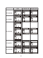
Set temperature:
TWS/T5S:SETTING TEMPERATURE;TW:TOTAL OUTLET WATER TEMPERATURE,
T5:TANK TEMPERATURE;TSF:SAFE TEMPERATURE;
DAILY TIMER / WEEKLY SCHEDULE / ERROR / LOCK
7

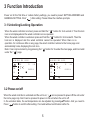
3 Function Introduction
Power on for the first time or restore factory settings, you need to preset: SETTING ADDRESS and
GENERAL SETTING. Click “ ” after setting. Please follow the interface prompts.
3.1 Unlocking/Locking Operation
When the wired controller is locked, press and hold the " " button for 3s to unlock it. Then the lock
icon is not displayed and the wired controller can be operated.
When the wired controller is unlocked. press and hold the " " button for 3s to locked it. Then the
lock icon is displayed and the wired controller cannot be operated. When there is no
operation for continuous 60s on any page, the wired controller returns to the home page and
automatically locks, displaying the lock icon.
Note: It can only be locked by long pressing the " " button for 3s under the main page, and it is invalid
under the " " page.
3.2 Power-on/off
When the wired controller is unlocked and the unit is on, “ ” can be pressed to power off the unit under
the home page only. And it can be pressed to power on the unit when the unit is off.
In the unlocked state, the set temperature can be adjusted by pressing▲▼button. And you need to
Press “ ”button to confirm after setting. It’s invalid without confirmation within 5s.
Operating Introduction:
Press "▲" "▼" to select TIMER, ACT, TIME ON, TIME OFF, MODE, TWS or SILENT MODE. When
the cursor stays at “TIMER ”, press "◄" and "►" to select “TIMER 1” or “TIMER 2”. When it stays at
other items, we can also use “ ◄”, “ ►” to adjust corresponding settings.
After setting, press " " to confirm saving, or press " " to cancel setting and return to the
previous interface.
If Time1 T.ON is set the same as Time1 T.OFF, then the setting is invalid, the ACT option for the timer
of this segment jumps to "OFF", the setting of Timer2 is the same as that of Timer1, and the timing
interval of Time2 can cross with that of Time1.
For example, if Timer1 T.ON is set to 12:00 and Timer1 T.OFF is set to 15:00, then the values of
Timer2 T.ON and Time2 T.OFF can be set in the range of 12:00-15:00. If the time interval crosses,
the machine will be powered on at the time T.ON which is set in Timer1 or Timer2, and will be
powered off at the time T.OFF which is set in Timer1 or Timer2.
After the daily timer function setting is enabled, there will be corresponding prompts displayed on
the homepage.
When two timers overlap, the second setting takes precedence.
Weekly schedule setting:
Select “WEEKLY SCHEDULE” and press“ ”. Display as follows:
12/04/2019 MON 10:35A
COOL
ON
45% 60%
TWTWS
ONLINE 16
9
C
7
C
12/04/2019 MON 10:35A
COOL
ON
45% 60%
TWTWS
ONLINE 16
9
C
7
C
5

LOCK UNLOCK: ON UNLOCK: OFF
HP-COOLING
CO-COOLING
FC-COOLING
HP-HEATING
HP-HOTWATER
Operating Introduction:
Press "▲" "▼" to select TIMER, ACT, TIME ON, TIME OFF, MODE, TWS or SILENT MODE. When
the cursor stays at “TIMER ”, press "◄" and "►" to select “TIMER 1” or “TIMER 2”. When it stays at
other items, we can also use “ ◄”, “ ►” to adjust corresponding settings.
After setting, press " " to confirm saving, or press " " to cancel setting and return to the
previous interface.
If Time1 T.ON is set the same as Time1 T.OFF, then the setting is invalid, the ACT option for the timer
of this segment jumps to "OFF", the setting of Timer2 is the same as that of Timer1, and the timing
interval of Time2 can cross with that of Time1.
For example, if Timer1 T.ON is set to 12:00 and Timer1 T.OFF is set to 15:00, then the values of
Timer2 T.ON and Time2 T.OFF can be set in the range of 12:00-15:00. If the time interval crosses,
the machine will be powered on at the time T.ON which is set in Timer1 or Timer2, and will be
powered off at the time T.OFF which is set in Timer1 or Timer2.
After the daily timer function setting is enabled, there will be corresponding prompts displayed on
the homepage.
When two timers overlap, the second setting takes precedence.
Weekly schedule setting:
Select “WEEKLY SCHEDULE” and press“ ”. Display as follows:
12/04/2019 MON 10:35A
COOL
ON
45% 60%
TWTWS
ONLINE 16
9
C
7
C
12/04/2019 MON 10:35A
COOL
ON
45% 60%
TWTWS
ONLINE 16
9
C
7
C
12/04/2019 MON 10:35A
COOL
TWTWS
ONLINE 16
9
C
7
C
12/04/2019 MON 10:35A
COOL
ON
45% 60%
TWTWS
TSF
ONLINE 16
9
C
75
C
C
12/04/2019 MON 10:35A
COOL
ON
45% 60%
TWTWS
TSF
ONLINE 16
9
C
75
C
C
12/04/2019 MON 10:35A
COOL
TWTWS
TSF
ONLINE 16
9
C
75
C
C
12/04/2019 MON 10:35A
FC
ON
45% 60%
TWTWS
TSF
ONLINE 16
9
C
75
C
C
12/04/2019 MON 10:35A
COMP
ON
45% 60%
TWTWS
TSF
ONLINE 16
9
C
75
C
C
12/04/2019 MON 10:35A
MIX
ON
45% 60%
TWTWS
TSF
ONLINE 16
9
C
75
C
C
12/04/2019 MON 10:35A
COMP
ON
45% 60%
TWTWS
TSF
ONLINE 16
9
C
75
C
C
12/04/2019 MON 10:35A
COMP
TWTWS
TSF
ONLINE 16
9
C
75
C
C
12/04/2019 MON 10:35A
HEAT
ON
45% 60%
TWTWS
ONLINE 16
40
C
55
C
12/04/2019 MON 10:35A
HEAT
ON
45% 60%
TWTWS
ONLINE 16
40
C
55
C
12/04/2019 MON 10:35A
HEAT
TWTWS
ONLINE 16
40
C
55
C
12/04/2019 MON 10:35A
DHW
ON
45% 60%
T5T5S
ONLINE 16
40
C
60
C
12/04/2019 MON 10:35A
DHW
ON
45% 60%
T5T5S
ONLINE 16
40
C
60
C
12/04/2019 MON 10:35A
DHW
45% 60%
T5T5S
ONLINE 16
40
C
60
C
6

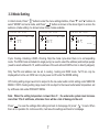
3.3 Mode Setting
In Unlock mode, Press " " button to enter the menu setting interface, Press "▼" and "▲" buttons to
select "MODE" and set a mode, and Press " " button as shown in the above figure to access the
submenu (mode setting). As shown below: three modes available.
Cycle: Cooling-->Heating-->DHW-->Cooling. Skip the mode cycle when there is no corresponding
mode. The DHW mode is divided into single pump (no need to select the address) and multiple pumps
(need to select address 00-15, and the address of the unit without DHW function is directly skipped).
Only Tws/T5s and address can be set in coolingheating and DHW mode. Tw/T5 can only be
displayed but not be set. DHW can only be power on/off under the MODE setting.
HP-Cooling setting range lower limit is subject to the low water outlet control setting under SERVICE
MENU. CO/FC-Cooling setting range lower limit is subject to the lowest outlet water temperature set
by antifreeze ratio under PROJECT MENU.
NoteWhen the setting temperature is lower than 5, the water-side system must increase
more than 15% of antifreeze, otherwise there will be a risk of damage to the unit.
Press “ ” to save the settings after setting and back to homepage. Or press“ ” to back. When
there is no operation for continuous 60s, it will save the settings and back to homepage.
Operating Introduction:
Press "▲" "▼" to select TIMER, ACT, TIME ON, TIME OFF, MODE, TWS or SILENT MODE. When
the cursor stays at “TIMER ”, press "◄" and "►" to select “TIMER 1” or “TIMER 2”. When it stays at
other items, we can also use “ ◄”, “ ►” to adjust corresponding settings.
After setting, press " " to confirm saving, or press " " to cancel setting and return to the
previous interface.
If Time1 T.ON is set the same as Time1 T.OFF, then the setting is invalid, the ACT option for the timer
of this segment jumps to "OFF", the setting of Timer2 is the same as that of Timer1, and the timing
interval of Time2 can cross with that of Time1.
For example, if Timer1 T.ON is set to 12:00 and Timer1 T.OFF is set to 15:00, then the values of
Timer2 T.ON and Time2 T.OFF can be set in the range of 12:00-15:00. If the time interval crosses,
the machine will be powered on at the time T.ON which is set in Timer1 or Timer2, and will be
powered off at the time T.OFF which is set in Timer1 or Timer2.
After the daily timer function setting is enabled, there will be corresponding prompts displayed on
the homepage.
When two timers overlap, the second setting takes precedence.
Weekly schedule setting:
Select “WEEKLY SCHEDULE” and press“ ”. Display as follows:
12/04/2019 MON 10:35A
COOL
TWTWS 9
C
7
C
12/04/2019 MON 10:35A
HEAT
TWTWS 40
C
55
C
12/04/2019 MON 10:35A
DHW
T5T5S 40
C
60
C
7

8
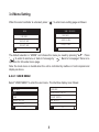
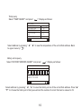
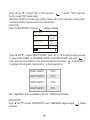
3.4 Menu Setting
When the wired controller is unlocked, press “ ” to enter menu setting page as follows:
The default selection is “MODE” and choose the menu you need by pressing "▲▼" . Press
“ ” to enter its submenu or back to homeage by “ ”. Back to homepage if there is no
operation for 60s under menu page.
Note: the mode menu is invalid when the unit is controlled by modbus or host computer and
display as above.
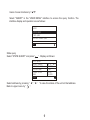
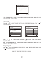
4.3.6.1 USER MENU
Select "USER MENU" to enter the user menu. The interface display is as follows:
Operating Introduction:
Press "▲" "▼" to select TIMER, ACT, TIME ON, TIME OFF, MODE, TWS or SILENT MODE. When
the cursor stays at “TIMER ”, press "◄" and "►" to select “TIMER 1” or “TIMER 2”. When it stays at
other items, we can also use “ ◄”, “ ►” to adjust corresponding settings.
After setting, press " " to confirm saving, or press " " to cancel setting and return to the
previous interface.
If Time1 T.ON is set the same as Time1 T.OFF, then the setting is invalid, the ACT option for the timer
of this segment jumps to "OFF", the setting of Timer2 is the same as that of Timer1, and the timing
interval of Time2 can cross with that of Time1.
For example, if Timer1 T.ON is set to 12:00 and Timer1 T.OFF is set to 15:00, then the values of
Timer2 T.ON and Time2 T.OFF can be set in the range of 12:00-15:00. If the time interval crosses,
the machine will be powered on at the time T.ON which is set in Timer1 or Timer2, and will be
powered off at the time T.OFF which is set in Timer1 or Timer2.
After the daily timer function setting is enabled, there will be corresponding prompts displayed on
the homepage.
When two timers overlap, the second setting takes precedence.
Weekly schedule setting:
Select “WEEKLY SCHEDULE” and press“ ”. Display as follows:
MODE (DISABLE)
USER MENU
SERVICE MENU
PROJECT MENU
OK
MODE
USER MENU
SERVICE MENU
PROJECT MENU
OK
USER MENU
TIMER
OK
GENERAL SETTING
DOUBLE SETPOINT
1/2
QUERY
USER MENU
SILENT SWITCH
OK
DHW SWITCH
2/2
SNOW-BLOWING SWITCH

1
9
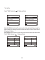
Users choose functions by "▲▼".
Select "QUERY" in the "USER MENU" interface to access the query function. The
interface display and operation are as follows:
State query
Select “STATE QUERY” and press“ ”. Display as follows:
Select address by pressing “ ◄”, “ ►” ”to view the status of the unit at that address.
Back to upper menu by “ ”.
Operating Introduction:
Press "▲" "▼" to select TIMER, ACT, TIME ON, TIME OFF, MODE, TWS or SILENT MODE. When
the cursor stays at “TIMER ”, press "◄" and "►" to select “TIMER 1” or “TIMER 2”. When it stays at
other items, we can also use “ ◄”, “ ►” to adjust corresponding settings.
After setting, press " " to confirm saving, or press " " to cancel setting and return to the
previous interface.
If Time1 T.ON is set the same as Time1 T.OFF, then the setting is invalid, the ACT option for the timer
of this segment jumps to "OFF", the setting of Timer2 is the same as that of Timer1, and the timing
interval of Time2 can cross with that of Time1.
For example, if Timer1 T.ON is set to 12:00 and Timer1 T.OFF is set to 15:00, then the values of
Timer2 T.ON and Time2 T.OFF can be set in the range of 12:00-15:00. If the time interval crosses,
the machine will be powered on at the time T.ON which is set in Timer1 or Timer2, and will be
powered off at the time T.OFF which is set in Timer1 or Timer2.
After the daily timer function setting is enabled, there will be corresponding prompts displayed on
the homepage.
When two timers overlap, the second setting takes precedence.
Weekly schedule setting:
Select “WEEKLY SCHEDULE” and press“ ”. Display as follows:
QUERY
TEMP QUERY
OK
HISTORY ERRORS QUERY
STATE QUERY
STATE QUERY
SELECT ADDESS
STANDBY
COOL
NIGHT
SILENT1
OPERATION STATE
11 #
RUNNING MODE
CURREN SLIENT
MODE
BACK

2
10
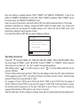
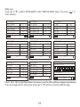
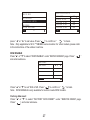
Temp query
Select “TEMP QUERY” and press“ ”. Display as follows:
Select address by pressing “ ◄”, “ ►” to view the temperature of the unit at that address. Back
to upper menu by “ ”.
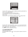
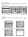
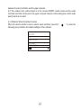
History errors query
Select “HISTORY ERRORS QUERY” and press“ ”. Display as follows:
Select address by pressing “ ◄”, “ ►” to view the history errors of the unit at that address. Press "▲"
"▼" to choose the history error that you want and the number of errors that can be viewed is 16.
Operating Introduction:
Press "▲" "▼" to select TIMER, ACT, TIME ON, TIME OFF, MODE, TWS or SILENT MODE. When
the cursor stays at “TIMER ”, press "◄" and "►" to select “TIMER 1” or “TIMER 2”. When it stays at
other items, we can also use “ ◄”, “ ►” to adjust corresponding settings.
After setting, press " " to confirm saving, or press " " to cancel setting and return to the
previous interface.
If Time1 T.ON is set the same as Time1 T.OFF, then the setting is invalid, the ACT option for the timer
of this segment jumps to "OFF", the setting of Timer2 is the same as that of Timer1, and the timing
interval of Time2 can cross with that of Time1.
For example, if Timer1 T.ON is set to 12:00 and Timer1 T.OFF is set to 15:00, then the values of
Timer2 T.ON and Time2 T.OFF can be set in the range of 12:00-15:00. If the time interval crosses,
the machine will be powered on at the time T.ON which is set in Timer1 or Timer2, and will be
powered off at the time T.OFF which is set in Timer1 or Timer2.
After the daily timer function setting is enabled, there will be corresponding prompts displayed on
the homepage.
When two timers overlap, the second setting takes precedence.
Weekly schedule setting:
Select “WEEKLY SCHEDULE” and press“ ”. Display as follows:
TEMP QUERY
SELECT ADDESS
25 ℃
INLET WATER TEMP
11 #
OUTLET WATER TEMP
TOTAL OUTWATER
TEMP
BACK
25 ℃
25 ℃
AMBIENT TEMP
25 ℃
HISTORY ERRORSOUERY
SELECT ADDESS
11 #
E2:11/3/2020 15:05P
COMMUNICATION ERROR
OK
122 3 74 5 6 8

3
11
Select address by pressing “ ◄”, “ ►” to view the history errors of the unit at that address. Press "▲"
"▼" to choose the history error that you want and the number of errors that can be viewed is 16.
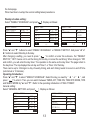
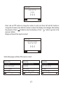
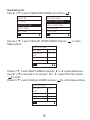
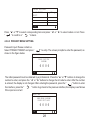
Timer setting
Select “TIMER” and press“ ”. Display as follows:
Note: After MODBUS control and the remote control of the external machine are used, the
daily and weekly time settings of the wired controller are invalid, and users cannot enter the
timing menu for setting.
When MODBUS control and the remote control of the external machine are invalid. Select
“DAILY TIMER” and press“ ”. Display as follows:
Operating Introduction:
Press "▲" "▼" to select TIMER, ACT, TIME ON, TIME OFF, MODE, TWS or SILENT MODE. When
the cursor stays at “TIMER ”, press "◄" and "►" to select “TIMER 1” or “TIMER 2”. When it stays at
other items, we can also use “ ◄”, “ ►” to adjust corresponding settings.
After setting, press " " to confirm saving, or press " " to cancel setting and return to the
previous interface.
If Time1 T.ON is set the same as Time1 T.OFF, then the setting is invalid, the ACT option for the timer
of this segment jumps to "OFF", the setting of Timer2 is the same as that of Timer1, and the timing
interval of Time2 can cross with that of Time1.
For example, if Timer1 T.ON is set to 12:00 and Timer1 T.OFF is set to 15:00, then the values of
Timer2 T.ON and Time2 T.OFF can be set in the range of 12:00-15:00. If the time interval crosses,
the machine will be powered on at the time T.ON which is set in Timer1 or Timer2, and will be
powered off at the time T.OFF which is set in Timer1 or Timer2.
After the daily timer function setting is enabled, there will be corresponding prompts displayed on
the homepage.
When two timers overlap, the second setting takes precedence.
Weekly schedule setting:
Select “WEEKLY SCHEDULE” and press“ ”. Display as follows:
TIMER
WEEKLY SCHEDULE
OK
DAILY TIMER
TIMER
WEEKLY SCHEDULE(DISABLE)
OK
DAILY TIMER(DISABLE)
DAILY TIMER
TIMER
ACT
1 #
OK
0FF
1/2
TIME ON
TIME OFF
MODE
10:00 A
10:00 A
HEAT
DAILY TIMER
TWS
SILENT MODE
40 ℃
OK
NIGHT
2/2
SILENT1

4
12
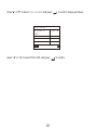
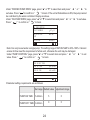
Only one setting is enabled between "DAILY TIMER" and "WEEKLY SCHEDULE". If any of the
pattern in "WEEKLY SCHEDULE" is set to ON, "DAILY TIMER" is disabled. "DAILY TIMER" can be
set across days, but "WEEKLY SCHEDULE" can’t.
Users can set up to two timers, and set the ON or OFF time (set the interval of time to 10 minutes)
operation mode(there are heating, cooling and DHW modes for single pump; only cooling and
heating modes can be selected for multiple pumps, and it cannot be set as DHW mode ) and
temperature setting for each segment of timer.
It’s invalid if the ON and OFF time are same. Display as follows:
Operating Introduction:
Press "▲" "▼" to select TIMER, ACT, TIME ON, TIME OFF, MODE, TWS or SILENT MODE. When
the cursor stays at “TIMER ”, press "◄" and "►" to select “TIMER 1” or “TIMER 2”. When it stays at
other items, we can also use “ ◄”, “ ►” to adjust corresponding settings.
After setting, press " " to confirm saving, or press " " to cancel setting and return to the
previous interface.
If Time1 T.ON is set the same as Time1 T.OFF, then the setting is invalid, the ACT option for the timer
of this segment jumps to "OFF", the setting of Timer2 is the same as that of Timer1, and the timing
interval of Time2 can cross with that of Time1.
For example, if Timer1 T.ON is set to 12:00 and Timer1 T.OFF is set to 15:00, then the values of
Timer2 T.ON and Time2 T.OFF can be set in the range of 12:00-15:00. If the time interval crosses,
the machine will be powered on at the time T.ON which is set in Timer1 or Timer2, and will be
powered off at the time T.OFF which is set in Timer1 or Timer2.
After the daily timer function setting is enabled, there will be corresponding prompts displayed on
the homepage.
When two timers overlap, the second setting takes precedence.
Weekly schedule setting:
Select “WEEKLY SCHEDULE” and press“ ”. Display as follows:
Timer is useless.
The start time is same to
the end time.
OK
DAILY TIMER

13
Operating Introduction:
Press "▲" "▼" to select TIMER, ACT, TIME ON, TIME OFF, MODE, TWS or SILENT MODE. When
the cursor stays at “TIMER ”, press "◄" and "►" to select “TIMER 1” or “TIMER 2”. When it stays at
other items, we can also use “ ◄”, “ ►” to adjust corresponding settings.
After setting, press " " to confirm saving, or press " " to cancel setting and return to the
previous interface.
If Time1 T.ON is set the same as Time1 T.OFF, then the setting is invalid, the ACT option for the timer
of this segment jumps to "OFF", the setting of Timer2 is the same as that of Timer1, and the timing
interval of Time2 can cross with that of Time1.
For example, if Timer1 T.ON is set to 12:00 and Timer1 T.OFF is set to 15:00, then the values of
Timer2 T.ON and Time2 T.OFF can be set in the range of 12:00-15:00. If the time interval crosses,
the machine will be powered on at the time T.ON which is set in Timer1 or Timer2, and will be
powered off at the time T.OFF which is set in Timer1 or Timer2.
After the daily timer function setting is enabled, there will be corresponding prompts displayed on
the homepage.
When two timers overlap, the second setting takes precedence.
Weekly schedule setting:
Select “WEEKLY SCHEDULE” and press“ ”. Display as follows:
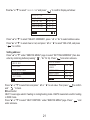
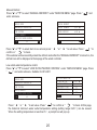
Press "▲" and "▼" buttons to select “WEEKLY SCHEDULE” or “WEEKLY SWITCH”. And press “◄ ”or“
►” buttons to select Monday to Sunday.
After changing a setting, you need to press “ ” to confirm or enter the submenu. For “WEEKLY
SWITCH”, “OFF” means not to set the timing for this day or cancel the set timing. When change to “ON”
and confirm, you will enter the day timer. The operation is the same as the day timer. The page refers to
the day timer. The top displays the set day and Timer 1 or Timer 2 for that day.
There can be up to 2 timings in a day of weekly timing, and each timing needs to be set on and off time
(set interval is 10 minutes).
Operating Introduction:
Press "▲" and "▼" to select “WEEKLY SCHEDULE”. Select the day you need by “ ◄ ” or “ ► ”, and
press “ ” to enter it. Then you can switch between TIMER, ACT, TIME ON, TIME OFF, MODE, TWS
and SILENT MODE by "▲" and "▼" . Refer to the operating introduction of “DAILY TIMER”.
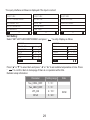
General setting:
Select “GENERAL SETTING” and press“ ”. Display as follows:
WEEKLY SCHEDULE
WEEKLY SCHEDULE
WEEKLY SWITCH
MON
OK
OFF
MONDAY TIMER
TIMER
ACT
1 #
OK
0FF
1/2
TIME ON
TIME OFF
MODE
10:00 A
10:00 A
HEAT
MONDAY TIMER
TWS
SILENT MODE
40 ℃
OK
NIGHT
2/2
SILENT1
GENERAL SETTING
YEAR
MONTH
2020
OK
12
1/2
DAY
12-24HOUR
HOUR
10
12
10
GENERAL SETTING
MINUTE
AMPM
55
OK
AM
2/2
LANGUAGE
BACKLIGHT
OFF DELAY(s)
ENGLISH
20
5

14
Operating Introduction:
Press "▲" "▼" to select TIMER, ACT, TIME ON, TIME OFF, MODE, TWS or SILENT MODE. When
the cursor stays at “TIMER ”, press "◄" and "►" to select “TIMER 1” or “TIMER 2”. When it stays at
other items, we can also use “ ◄”, “ ►” to adjust corresponding settings.
After setting, press " " to confirm saving, or press " " to cancel setting and return to the
previous interface.
If Time1 T.ON is set the same as Time1 T.OFF, then the setting is invalid, the ACT option for the timer
of this segment jumps to "OFF", the setting of Timer2 is the same as that of Timer1, and the timing
interval of Time2 can cross with that of Time1.
For example, if Timer1 T.ON is set to 12:00 and Timer1 T.OFF is set to 15:00, then the values of
Timer2 T.ON and Time2 T.OFF can be set in the range of 12:00-15:00. If the time interval crosses,
the machine will be powered on at the time T.ON which is set in Timer1 or Timer2, and will be
powered off at the time T.OFF which is set in Timer1 or Timer2.
After the daily timer function setting is enabled, there will be corresponding prompts displayed on
the homepage.
When two timers overlap, the second setting takes precedence.
Weekly schedule setting:
Select “WEEKLY SCHEDULE” and press“ ”. Display as follows:
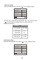
Press "▲" and "▼" to select the date, time, and time format to be set. Adjust their parameters
by “ ◄ ” or “ ►”, and press “ ” to save. The backlight time setting range is 10-1200s, the
default is 60s, and each adjustment is 10s.
Back to previous page by “ ” after setting. Only English is supported now.
Double Setpoint
Select “DOUBLE SETPOINT” and press“ ”. Display as follows:
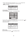
Press "▲" and "▼" to select items and “ ◄ ” or “ ►” to adjust parameters.
the lower limit of the set range of HP refrigeration is subject to the low water outlet control set under
SERVICE MENU, and the lower limit set for CO/FC refrigeration is subject to the minimum water
outlet set under the antifreeze ratio set under PROJECT MENU.
Snow-Blowing switch
Select “SNOW-BLOWING SWITCH” under “USER MENU” page and press“ ”. Display as follows:
DOUBLE SETPOINT
DOUBLE SETPOINT
DISABLE
OK
16 ℃
SETPOINT COOL_1
SETPOINT COOL_2
20 ℃
SETPOINT HEAT_1
SETPOINT HEAT_2
16 ℃
25 ℃
SNOW-BLOWING SWITCH
YES
OK
SNOW-BLOWING SWITCH
6

15
Operating Introduction:
Press "▲" "▼" to select TIMER, ACT, TIME ON, TIME OFF, MODE, TWS or SILENT MODE. When
the cursor stays at “TIMER ”, press "◄" and "►" to select “TIMER 1” or “TIMER 2”. When it stays at
other items, we can also use “ ◄”, “ ►” to adjust corresponding settings.
After setting, press " " to confirm saving, or press " " to cancel setting and return to the
previous interface.
If Time1 T.ON is set the same as Time1 T.OFF, then the setting is invalid, the ACT option for the timer
of this segment jumps to "OFF", the setting of Timer2 is the same as that of Timer1, and the timing
interval of Time2 can cross with that of Time1.
For example, if Timer1 T.ON is set to 12:00 and Timer1 T.OFF is set to 15:00, then the values of
Timer2 T.ON and Time2 T.OFF can be set in the range of 12:00-15:00. If the time interval crosses,
the machine will be powered on at the time T.ON which is set in Timer1 or Timer2, and will be
powered off at the time T.OFF which is set in Timer1 or Timer2.
After the daily timer function setting is enabled, there will be corresponding prompts displayed on
the homepage.
When two timers overlap, the second setting takes precedence.
Weekly schedule setting:
Select “WEEKLY SCHEDULE” and press“ ”. Display as follows:
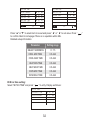
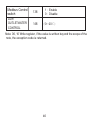
Press "▲" and "▼" to select “YES” or “NO” and press “ ” to confirm. "YES" means the
function is valid, "NO" means invalid.
Note:Some models do not have this function. Please refer to the instructions of the outdoor
machine for whether they have anti-snow control function.
Silent mode:
Select “SILENT SWITCH” and press“ ”. Display as follows:
Press "▲" and "▼" to select “SELECT SILENT”, press“ ◄ ” or “ ►” to select the mode you need
(7 types: NIGHT SILENT1-4, STANDARD, SILENT and SUPER SILENT), and press “ ” to
save. Users can check whether it is the mode they want here and press “ ” to back if there is
no problem. Once the silent mode turned on, in homepage light up.
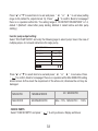
NIGHT SILENT 1
NIGHT SILENT 2
NIGHT SILENT 3
NIGHT SILENT 4
6/10h
8/12h
8/10h
6/12h
NoteNight Silent1-4 is only available for MC-SU **-RN8L-B series models.
DHW SWITCH
Press "▲" and "▼" to select “DHW SWITCH” under “USER MENU” page and press “ ”. Display
as follows:
SILENT SWITCH
SELECT SILENT
OK
CURRENT SILENT
NIGHT
SILENT1
NIGHT
SILENT1
7
Page is loading ...
Page is loading ...
Page is loading ...
Page is loading ...
Page is loading ...
Page is loading ...
Page is loading ...
Page is loading ...
Page is loading ...
Page is loading ...
Page is loading ...
Page is loading ...
Page is loading ...
Page is loading ...
Page is loading ...
Page is loading ...
Page is loading ...
Page is loading ...
Page is loading ...
Page is loading ...
Page is loading ...
Page is loading ...
Page is loading ...
Page is loading ...
Page is loading ...
Page is loading ...
Page is loading ...
Page is loading ...
Page is loading ...
Page is loading ...
Page is loading ...
Page is loading ...
Page is loading ...
Page is loading ...
Page is loading ...
Page is loading ...
-
 1
1
-
 2
2
-
 3
3
-
 4
4
-
 5
5
-
 6
6
-
 7
7
-
 8
8
-
 9
9
-
 10
10
-
 11
11
-
 12
12
-
 13
13
-
 14
14
-
 15
15
-
 16
16
-
 17
17
-
 18
18
-
 19
19
-
 20
20
-
 21
21
-
 22
22
-
 23
23
-
 24
24
-
 25
25
-
 26
26
-
 27
27
-
 28
28
-
 29
29
-
 30
30
-
 31
31
-
 32
32
-
 33
33
-
 34
34
-
 35
35
-
 36
36
-
 37
37
-
 38
38
-
 39
39
-
 40
40
-
 41
41
-
 42
42
-
 43
43
-
 44
44
-
 45
45
-
 46
46
-
 47
47
-
 48
48
-
 49
49
-
 50
50
-
 51
51
-
 52
52
-
 53
53
-
 54
54
-
 55
55
-
 56
56


Sinclair SCV-750EBH User manual
- Type
- User manual
- This manual is also suitable for
Ask a question and I''ll find the answer in the document
Finding information in a document is now easier with AI
Related papers
Other documents
-
 Kaysun Individual Wireless controller KCCHT-06 MODBUS User manual
-
 Kaysun Individual Wired Controller KCCHT-05 MODBUS User manual
-
Carrier R32 User manual
-
Honeywell SV2 Series Valve Programming Tools HMITOOL-000, PCTOOL-000 Operating instructions
-
SystemAir TSF-200 Operating instructions
-
SystemAir TSF-250 Operating instructions
-
SystemAir TSF-160 Installation guide
-
mundoclima Series MUENR-H7 “DC Inverter Modular Chiller” User manual
-
Alpha innotec Lux 21 Teil 2 Owner's manual
-

