
ORIGINAL INSTRUCTIONS
PORTABLE BEVELLING MACHINE
EUROBOOR B45

2 INSTRUCTION MANUAL EUROBOOR B45 Version: 1.0 EN

Version: 1.0 EN INSTRUCTION MANUAL EUROBOOR B45 3
TABLE OF CONTENTS
SAFETY 4
GENERAL SAFETY INFORMATION 4
SPECIFIC SAFETY INFORMATION 6
DESCRIPTION 8
INTENDED USE 8
TECHNICAL DATA 8
NOISE 8
VIBRATON 8
BOX CONTENTS 8
DESCRIPTION & FEATURES 9
SYMBOLS 10
NOISE & VIBRATION INFORMATION 11
PREPARATION & ADJUSTMENT 12
UNPACKING 12
FINAL ASSEMBLY 12
SETTING-ZERO POSITION 13
SETTING BEVEL DEPTH 14
OPERATION 15
STARTING & STOPPING 15
USING THE MACHINE 16
MAINTENANCE 17
CLEANING AND LUBRICATING 17
CHANGING OR REPLACING THE MILLING HEAD 17
ROTATING AND REPLACING CUTTING PLATES 19
REPLACING THE IMPELLER 20
REPLACING CARBON BRUSHES 20
ACCESSORIES & CONSUMABLES 22
ACCESSORIES 22
CONSUMABLES 22
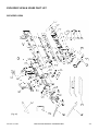
EXPLODED VIEW & SPARE PART LIST 23
EXPLODED VIEW 23
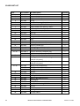
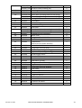
SPARE PART LIST 24
WARRANTY & SERVICE 26
WARRANTY 26
SERVICE 26
NOTES 26
ADDITIONAL INFORMATION 27
CERTIFICATION 27

4 INSTRUCTION MANUAL EUROBOOR B45 Version: 1.0 EN
SAFETY
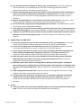
GENERAL SAFETY INFORMATION
READ AND UNDERSTAND ALL SAFETY INFORMATION AND INSTRUCTIONS. FAILURE TO FOLLOW THE
WARNINGS AND INSTRUCTIONS MAY RESULT IN ELECTRIC SHOCK, FIRE AND/OR SERIOUS INJURY.
SAVE ALL WARNINGS AND INSTRUCTIONS FOR FUTURE REFERENCE.
THE TERM “POWER TOOL” IN THE WARNINGS REFERS TO YOUR MAINS-OPERATED CORDED POWER
TOOL.
1. WORK AREA SAFETY
a) Keep work area clean and well lit. Cluttered and dark areas invite accidents.
b) Do not operate power tools in explosive atmospheres, such as in the presence of
flammable liquids, gases or dust. Power tools create sparks which may ignite the dust or
fumes.
c) Keep children and bystanders away while operating a power tool. Distractions can cause
you to lose control.
2. ELECTRICAL SAFETY
a) Power tool plugs must match the outlet. Never modify the plug in any way. Do not use any
adapter plugs with earthed (grounded) power tools. Unmodified plugs and matching outlets
will reduce risk of electric shock
b) Avoid body contact with earthed or grounded surfaces such as pipes, radiators, ranges and
refrigerators. There is an increased risk of electric shock if your body is earthed or grounded.
c) Do not expose power tools to rain or wet conditions. Water entering a power tool will
increase the risk of electric shock.
d) Do not abuse the cord. Never use the cord for carrying, pulling or unplugging the power
tool. Keep cord away from heat, oil, sharp edges or moving parts. Damaged or entangled
cords increase the risk of electric shock.
e) When operating a power tool outdoors, use an extension cord suitable for outdoor use.
Use of a cord suitable for outdoor use reduces the risk of electric shock.
f) If operating a power tool in a damp location is unavoidable, use a residual current
device(RCD)protected supply. Use of an RCD reduces the risk of electric shock.
3. PERSONAL SAFETY
a) Stay alert, watch what you are doing and use common sense when operating a power tool.
Do not use a power tool while you are tired or under the influence of drugs, alcohol or
medication. A moment of inattention while operating power tools may result in serious
personal injury.

Version: 1.0 EN INSTRUCTION MANUAL EUROBOOR B45 5
b) Use personal protective equipment. Always wear eye protection. Protective equipment
such as dust mask, non-skid safety shoes, hard hat, or hearing protection used for
appropriate conditions will reduce personal injuries.
c) Prevent unintentional staring. Ensure the switch is in the off-position before connecting to
power source and /or battery pack, picking up or carrying the tool. Carrying power tools
with your finger on the switch or energising power tools that have the switch on invites
accidents.
d) Remove any adjusting key or wrench before turning the power tool on. A wrench or a key
left attached to a rotating part of the power tool may result in personal injury.
e) Do not overreach. Keep proper footing and balance at all times. This enables better control
of the power tool in unexpected situations.
f) Dress properly. Do not wear loose clothing or jewellery. Keep your hair, clothing and gloves
away from moving parts. Loose clothes, jewellery or long hair can be caught in moving parts.
g) If devices are provided for the connection of dust extraction and collection facilities, ensure
these are connected and properly used. Use of dust collection can reduce dust related
hazards.
4. POWER TOOL USE AND CARE
a) Do not force the power tool. Use the correct power tool for your application. The correct
power tool will do the job better and safer at the rate for which it was designed.
b) Do not use the power tool if the switch does not turn it on and off. Any power tool that
cannot be controlled with the switch is dangerous and must be repaired.
c) Disconnect the plug from the power source and/or the battery pack from the power tool
before making any adjustments, changing accessories, or storing power tools. Such
preventive safety measures reduce the risk of staring the power tool accidentally.
d) Store idle power tools out of the reach of children and do not allow persons unfamiliar
with the power tool or these instructions to operate the power tool. Power tools are
dangerous in the hands of untrained users.
e) Maintain power tools. Check for misalignment or binding of moving parts, breakage of
parts and any other condition that may affect the power tool’s operation. If damaged, have
the power tool repaired before use. Many accidents are caused by poorly maintained power
tools.
f) Keep cutting tools sharp and clean. Properly maintained cutting tools with sharp cutting
edges are less likely to bind and are easier to control.
g) Use the power tool, accessories and tool bits etc. in accordance with these instructions,
taking into account the working conditions and the work to be performed. Use of the
power tool for operations different from those intended could result in a hazardous
situation.
5. Service
a) Have your power tool serviced by a qualified repair person using only identical replacement
parts. This will ensure that the safety of the power tool is maintained.

6 INSTRUCTION MANUAL EUROBOOR B45 Version: 1.0 EN
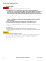
SPECIFIC SAFETY INFORMATION
1. ELECTRICAL SAFETY
ELECTRICAL VOLTAGE! RISK OF FATAL INJURY DUE TO ELECTRIC SHOCK!
a) Grounded tools must be plugged into an outlet properly installed and grounded in
accordance with all codes and ordinances. Never remove the grounding prong or modify the
plug in any way. Do not use adaptor plugs. Check with a qualified electrician if you are in
doubt whether the outlet is properly grounded. If the tools should electrically malfunction or
break down, grounding provides a low resistance path to carry electricity away from the user
b) When operation the tool outside, use an outdoor extension cord market “W-A” or “W”.
These cords are rated for outdoor use and reduce the risk of electric shock
c) Extension cables must have a sufficient cross-section so as to prevent an excessive drop in
voltage, or overheating. An excessive drop in voltage reduces the output an can lead to
failure of the motor
d) Never use multiple extensions cables together. Use a single longer one instead
e) Check the plug, cable and machine for damage each time using the machine
f) Remove the plug from the plug socket before undertaking an maintenance work on the
power tool
2. PERSONAL SAFETY
a) Check the plug, cable and machine for damage each time using the machine
b) Remove the plug from the plug socket before undertaking an maintenance work on the
power tool
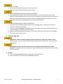
RISK OF INJURY FROM HIGH-TEMPERATURE CHIPS
c) Never touch the tool holder and keep all vulnerable body parts clear while the machine is
running, as high-temperature chips are expelled at high speed during operation
d) During operation, always guide the machine in a direction away from the body
e) Do not use the machine above your head

Version: 1.0 EN INSTRUCTION MANUAL EUROBOOR B45 7
RISK OF INJURY TO HANDS
f) Do not reach into the processing line with your hands
g) Use both hands to hold and operate the machine
DUST CREATED BY POWER GRINDING MAY HARM YOUR HEALTH
h) Some types of dust, such as dust from lead-based paint, is known to cause cancer, birth
defects or other reproductive harm. Risk varies on exposure and should always be reduced by
working in a well-ventilated area and by making use of approved safety equipment, such as
dust masks specifically designed to filter out microscopic particles
NEVER MACHINE MATERIALS WHICH CONTAIN ASBESTOS
i) Only use recommended triangle carbide inserts (“cutting plates”), rated at the machine’s
maximum cutting rate or higher
j) Do not use dull or damaged cutting plates to prevent excessive friction and load, and thus to
prevent damage to and failure of the machine
k) Maintain labels and identification plates, as they carry important information. If unreadable
or missing, obtain replacement
3. TOOL USE AND CARE
a) Hold power tool by insulated gripping surfaces, because the cutter may contact its own
cord. Cutting a “live” wire may make exposed metal parts of the power tool “live” and shock
the operator
b) Use clamps or another practical way to secure and support the workpiece to a stable
platform. Holding the work by your hand or against the body leaves it unstable and may lead
to loss of control.
4. SERVICE
a) Only use original EUROBOOR parts, accessories and consumables
b) Have maintenance carried out by EUROBOOR specialists

8 INSTRUCTION MANUAL EUROBOOR B45 Version: 1.0 EN
DESCRIPTION
INTENDED USE
This shape bevelling and deburring tool is an electrically driven portable machine for machining
workpieces in steel, chrome steel alloys, aluminium, aluminium alloys, brass and plastic. The machine is
designed exclusively for adding bevelled edges, rounding off edges, removing burrs and removing sharp
corners on workpieces. The speed of the machine is variable to suit the needs of various materials and is
equipped with a graduated depth adjustable deck. It comes standard with a 45° milling head for use
with triangle indexable cutter inserts (“cutting plates”) to achieve quick and easy bevelling. Optional 30°
and 45° R2.5 radius tool holders are available and can also be used.
The machine should not be used in any other way than described in this manual. The machine should
also not be converted or modified for any other form of use other than described in this manual. The
user is liable for damages and accidents resulting from any modifications made or incorrect use.
TECHNICAL DATA
Trademark: EUROBOOR
Model: B45
Rated voltage: 220-240V~ / 110-120V
Rated power (input): 1500W
Rated frequency: 50-60Hz
Spindle speed: 2000-6000/min (variable speed)
Bevel angle: 45 degree (optional 30 degree)
Spindle thread: M12x1.5mm
Max. bevel depth (45 degree): 6mm
Min. diameter for inside bevels: 20mm
Net weight: 4.6kg
BOX CONTENTS
- Protective case
- Bevelling machine
- Auxiliary front handle
- Standard 45 degree milling head
- Spanner 22mm
- C-spanner
- L-type Torx wrench
For an overview of accessories and consumables, see chapter ACCESSORIES & CONSUMABLES (page 21).
NOISE
L
pA
: 86.47dB(A)
L
wA
: 97.47dB(A)
Uncertainty K: 3dB(A)
VIBRATON
Main Handle: 2.738m/s
2
Aux. handle: 2.572m/s
2
Uncertainty K: 1.5m/s
2

Version: 1.0 EN INSTRUCTION MANUAL EUROBOOR B45 9
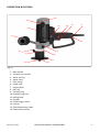
DESCRIPTION & FEATURES
[Fig. A]
1. Main handle
2. Auxiliary front handle
3. Motor housing
4. Motor cover
5. Gear casing
6. Power cord
7. Support deck
8. Dial ring
9. Clamping ring
10. Clamping ring lever
11. Milling head
12. Impeller
13. On/off trigger switch
14. Lock pin
15. Speed adjustment wheel
16. Carbon brush holder
16
3
2
15
14
13
6
1
4
5
10
9
12
8
7
11

10 INSTRUCTION MANUAL EUROBOOR B45 Version: 1.0 EN
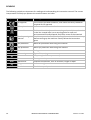
SYMBOLS
The following symbols are important for reading and understanding this instruction manual. The correct
interpretation will help you operate the machine better and safer.
Symbol Name Meaning
CE approval This machine has been tested for, and meets the safety standards
required for CE approval
Safety class II Indicates a double insulated tool
Do not bin If this machine is broken and can no longer be used do not throw it
in the bin. Instead offer it at a recycling point for safe and
environmental friendly disposal and future reuse of the materials
Read operating
manual
Read the operator’s manual and safety information in their entirety
before starting up the machine. Closely follow the instructions
given
Ear protection Wear ear protection while using this machine
Eye protection Wear eye protection while using this machine
V
Volt Voltage
~
Alternating current Type of alternating current
Hz
Hertz Frequency (oscillations per second)
W
Watt Power, power input
mm
Millimetres Indicates a dimension, such as thickness, length or depth
kg
Kilograms Indicates weight
/min
Revolutions Revolution speed per minute

Version: 1.0 EN INSTRUCTION MANUAL EUROBOOR B45 11
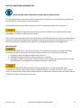
NOISE & VIBRATION INFORMATION
WEAR HEARING PROTECTION WHILE OPERATING THE POWER TOOLS
The declared vibration total value has been measured in accordance with a standard test method and
may be used for comparing one tool with another.
The declared vibration total value may also be used in a preliminary assessment of exposure
The vibration emission during actual use of the power tool can differ from the declared total value
depending on the ways in which the tool is used.
There is the need to identify safety measures to protect the operator that are bases on an estimation of
exposure in the actual conditions of use (taking account of all parts of the operating cycle such as the
times when the tool is switched off and when it is running idle in addition to the trigger time).
RESIDUAL RISKS
Even when the power tool is used as prescribed it is not possible to eliminate all residual risk factors.
The following hazards may arise in connection with the power tool’s construction and design:
1. Damage to lungs if an effective dust mask is not worn
2. Damage to hearing if effective hearing protection is not worn
3. Damages to health resulting from vibration emission if the power tool is being used over longer
period of time or not adequately managed and properly maintained.
This machine produced an electromagnetic field during operation. This field may under some
circumstances interfere with active or passive medical implants. To reduce the risk of serious or fatal
injury, we recommend persons with medical implants to consult their physician and the medical implant
manufacturer before operating this machine.

12 INSTRUCTION MANUAL EUROBOOR B45 Version: 1.0 EN
PREPARATION & ADJUSTMENT
UNPACKING
Carefully remove the machine, separate parts and accessories from the box. Retain all packing materials
until after you have inspected and satisfactorily operated the machine.
Make sure to dispose the packaging material responsibly and offer it for recycling.
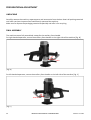
FINAL ASSEMBLY
The machine comes fully assembled, except for the auxiliary front handle.
For right handed operators, mount the auxiliary front handle on the right side of the machine [Fig. B]
[Fig. B]
For left handed operators, mount the auxiliary front handle on the left side of the machine [Fig. C]
[Fig. C]

Version: 1.0 EN INSTRUCTION MANUAL EUROBOOR B45 13
1) Enter the flat sided pin of the bar in the destined slot on the side of the machine firmly.
The bar of the front handle should be positioned in an 30 degree upward angle
2) Tighten the locking nut first by hand, and then firmly with the supplied spanner 22mm
(clockwise)
The machine should not be used without this auxiliary front handle, always make sure it is fitted
correctly and tightly before use.
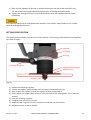
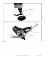
SETTING-ZERO POSITION
The machine’s bevel depth is set at zero from the factory. If the setting is disturbed, the zero position
has to be set again.
[Fig. D]
1) Loosen the clamping ring lever
2) Loosen the support deck assembly until the inserts are below flush level
3) Keep a steel ruler square on both the impeller and the support deck
4) Slowly adjust the support deck until the ruler just touches the cutting plate. This is the zero
position
5) Lock the clamping ring lever
6) Untighten the set screw in the dial
7) Rotate the dial ring until the zero matches the indicator on the machine
8) Retighten the set screw in the dial
Indicator
Dial ring
Set screw
Support deck assembly
Support deck
Clamping ring lever
Impeller

14 INSTRUCTION MANUAL EUROBOOR B45 Version: 1.0 EN
SETTING BEVEL DEPTH
[Fig. E]
1) Loosen the clamping ring lever
2) Rotate the entire support deck assembly, use the dial ring as indication for the depth
adjustment. Each complete rotation corresponds to a bevel depth of 1.5 mm (indicated on scale).
The bevel depth (in mm) is calculated as follows, with example:
[value on scale] + [value on dial ring] = bevel depth
1.5 + 0.7 = 2.2 mm
3) Tighten the clamping ring lever
Support deck assembly
Indicator
Dial ring
Clamping ring lever

Version: 1.0 EN INSTRUCTION MANUAL EUROBOOR B45 15
OPERATION
STARTING & STOPPING
Make sure the power circuit voltage is the same as shown on the specification plate on the machine.
Make sure the On/off trigger switch is in the “off” position before plugging in the machine.
[Fig. F]
Switching on
Press the On/off trigger switch [Fig. F] to start the machine. The anti-kickback and breakthrough torque
control provides a “slow start”: the machine needs a couple of seconds to reach its set running speed.
The On/off trigger switch can be locked in the “on” position by pressing the lock pin [Fig. F] while the
machine is running.
Controlling running speed
This machine is equipped with variable speed control. The speed adjustment wheel [Fig. F] can be rolled
down to increase the machine speed and up to decrease the machine speed.
Switching off
If the lock pin is not engaged, release the on/off trigger switch. [Fig. F]
If the lock pin is engaged, squeeze and release the on/off trigger switch. [Fig. F]
The milling head of the machine needs a couple of seconds to come to a complete standstill after the
machine has been switched off. Be careful for any chips that may be released by the rotation and make
sure that nothing touches the moving parts.
Overheat protection
This machine is equipped with an overheat protection which switches off the motor when running hot.
Allow the machine at least 5 minutes too cool off and let it run in idle for another couple of minutes
before resuming work.
Speed adjustment wheel
On/off trigger switch
Lock pin

16 INSTRUCTION MANUAL EUROBOOR B45 Version: 1.0 EN
USING THE MACHINE
- Make sure the machine is always in a stable position before and during use
- Do not operate the machine above your head
- Never touch the milling head while the machine is running
- Always operate the machine away from your body
- Work is performed with two-hand operation for all machine positions. When operation the
machine ensure that the machine is held with both hands in such a way that both hands are kept
away from the processing point. Make sure the auxiliary front handle is positioned correctly. For
details see chapter FINAL ASSEMBLY (page 12)
- Do not use this tool continuously for a period over 30 minutes
1) Set the speed adjustment wheel to the highest speed
2) Switch the machine on. Do not move the machine towards the workpiece until full speed has
been reached
3) Hold the machine in such a way that the support deck is flat on the workpiece
From the operator’s perspective, the milling head is spinning clockwise. The machine must always be
guided from left to right (conventional up milling), or clockwise when processing inside bevels.
4) Slightly push the machine against the workpiece and let the machine do its work. Lower the
speed of the machine if necessary (depending on the material of the workpiece) and slowly
move the machine in the correct direction to make the bevel. Avoid collisions during processing
Do not bevel more than 2mm depth per pass. If more depth is needed, adjust the bevelling depth in
steps of maximum 2mm and make multiple passes until the required depth is reached.
5) Once the bevelling pass is completed, take the machine from the workpiece
6) Switch the machine off
Note: adding cutting oil will improve operation and increase the life span of the cutting plates. See
chapter ACCESSORIES & CONSUMABLES (page 21) for more information.

Version: 1.0 EN INSTRUCTION MANUAL EUROBOOR B45 17
MAINTENANCE
Take care of the following before undertaking any maintenance work on the machine:
- Remove the plug from the socket
- Be careful for the sharp cutting plates in the milling head
- Be careful for hot components, like the motor and the milling head. Let the machine cool down
first after it has been used
- Wear safety gear, including gloves and glasses
Check the machine regularly for wear. Worn bearings in the milling head and blunt cutting plates are the
main cause for uneven finishes and rough and long operation. Replace worn components in good time
to reduce stress on the machine and increase its longevity.
Only use original EUROBOOR parts, accessories and consumables. Have maintenance carried out by
EUROBOOR specialists.
CLEANING AND LUBRICATING
Clean the machine after each use. Compressed air can be used to blow off dirt and blow out all air
passages. All plastic parts should be cleaned with a soft damp cloth. Never use solvents to clean plastic
parts.
Every 100 hours of operation, have the gearbox grease replaced by a qualified service technician.
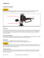
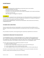
CHANGING OR REPLACING THE MILLING HEAD
The EUROBOOR B45 machine is standard equipped with a 45° milling head. When showing signs of
wear, a replacement piece (part number B45.1202) can be ordered from your EUROBOOR reseller.
Also available are a 30° milling head (part number B45.1201) and 45° with R2.5 radius milling head (part
number B45.1203). Both can be ordered as optional accessory from you EUROBOOR reseller.
For every type of milling head the replacement procedure is the same.
1) Loosen the clamping ring lever
2) Rotate the entire support deck assembly until it comes off the machine [Fig. G]
3) Use the supplied spanner 22mm to hold the spindle in place
4) Use the supplied C-spanner to loosen the milling head, and turn it off the machine [Fig. H]
Assembly in reversed order. Always check for damaged or worn-out parts and replace them when
necessary. Always clean and lubricate parts prior to refitting.

18 INSTRUCTION MANUAL EUROBOOR B45 Version: 1.0 EN
[Fig. G]
[Fig. H]
C
-
spanner
Spanner 22mm
Milling head
Clamping ring lever
Support deck assembly
Milling head

Version: 1.0 EN INSTRUCTION MANUAL EUROBOOR B45 19
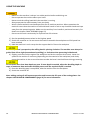
ROTATING AND REPLACING CUTTING PLATES
Each of the 3 cutting plates on the milling head has 3 usable sides. When the used side of either of the 3
cutting plates is dull, the cutting plates can be rotated to position a sharp side in the correct direction.
[Fig. I]
1) Remove the milling head as described in chapter CHANGING OR REPLACING THE MILLING HEAD
(page 16)
2) Clamp the milling head in a vice on the far outer rim
3) Mark dull side on all 3 cutting plates
4) Undo mounting screw with the supplied L-type Torx wrench
5) Take of cutting plate, rotate 120° and put it back in place
6) Fasten the mounting screw with the supplied L-type Torx wrench
7) Refit the milling head and other components as described in chapter CHANGING OR REPLACING
THE MILLING HEAD (page 16)
a) Always rotate the 3 cutting plates at the same time
b) Always replace the 3 cutting plates at the same time, using the same brand and type for all 3
pieces
Once all 3 sides of the cutting plates are used, they need to be replaced. Use official EUROBOOR cutting
plates to ensure the same quality and endurance. See chapter ACCESSORIES & CONSUMABLES (page 21)
for more information.
1) Undo mounting screw with the supplied L-type Torx wrench
2) Take of old cutting plate, put replacement piece in place
3) Fasten the mounting screw with the supplied L-type Torx wrench
Milling head
Cutting plate
Mounting screw

20 INSTRUCTION MANUAL EUROBOOR B45 Version: 1.0 EN
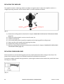
REPLACING THE IMPELLER
The impeller contains 2 bearings which are subject to regular wear. A worn-out impeller results in a
roughly operating machine and an uneven bevel. It can be replaced as follows:
[Fig. J]
1) Remove the milling head as described in chapter CHANGING OR REPLACING THE MILLING HEAD
(page 16)
2) Clamp the milling head in a vice on the far outer rim
3) Undo the locking nut
4) Use a small pulley puller to pull the impeller with its bearings off the milling head
5) Gently tap the new impeller with bearings into place
6) Replace the locking nut and fasten it
7) Refit the milling head and other components as described in chapter CHANGING OR REPLACING
THE MILLING HEAD (page 16)
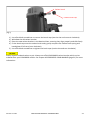
REPLACING CARBON BRUSHES
Carbon brushes are normal wearing parts and may need replacement after a longer time of use. The
motor of the machine comes to a standstill whenever the brushes are worn out.
To prevent sudden standstill during operation, replacing the carbon brushes when they reach their wear
limit [Fig. K] is advised.
[Fig. K]
Locking nut
Impeller
Page is loading ...
Page is loading ...
Page is loading ...
Page is loading ...
Page is loading ...
Page is loading ...
Page is loading ...
Page is loading ...
-
 1
1
-
 2
2
-
 3
3
-
 4
4
-
 5
5
-
 6
6
-
 7
7
-
 8
8
-
 9
9
-
 10
10
-
 11
11
-
 12
12
-
 13
13
-
 14
14
-
 15
15
-
 16
16
-
 17
17
-
 18
18
-
 19
19
-
 20
20
-
 21
21
-
 22
22
-
 23
23
-
 24
24
-
 25
25
-
 26
26
-
 27
27
-
 28
28


Ask a question and I''ll find the answer in the document
Finding information in a document is now easier with AI
Related papers
-
Euroboor B45S User manual
-
-
-
-
Euroboor EBS.500 Owner's manual
-
-
-
-
-
Other documents
-
Nordic PORO1610 User manual
-
SteelMax SM-ABM-30 Owner's manual
-
-
Trumpf TKF 1500-0 PLUS User manual
-
-
-
-
JET 894050 Owner's manual
-
-
Grizzly G0795Z Owner's manual