Page is loading ...

Operating Instructions
Model 682
Dual Beam Photometer
BA 905C/24/ae/01.07


Table of Contents
1.0 GENERAL INFORMATION..........................................................................................................................1
1.1 HOW THE MODEL 682 WORKS......................................................................................................................1
2.0 SPECIFICATIONS.........................................................................................................................................1
2.1 MODEL 682 DUAL BEAM PHOTOMETER SPECIFICATIONS:...............................................................................1
Figure 1 – Model 682 Dual Beam Photometer Dimensions.........................................................................1
2.2 MODEL AF21 SERIES VIS/NIR INLINE SENSORS............................................................................................3
2.3 MODEL AF22 SERIES VIS/NIR INLINE SENSORS............................................................................................3
3.0 INSTALLATION............................................................................................................................................4
3.1 MODEL 682 TRANSMITTER INSTALLATION......................................................................................................4
3.2 MODEL 682 CABLES AND WIRING .................................................................................................................4
Figure 2 – Wire Terminal Preparation ..........................................................................................................4
3.3 TRANSMITTER TO SENSOR ELECTRICAL CONNECTIONS..................................................................................4
Figure 3 – Typical AF21 Wiring Diagram......................................................................................................5
Figure 4 – Typical AF22 Wiring Diagram......................................................................................................6
3.4 DC INPUT POWER OPTION ............................................................................................................................7
Figure 5 – Model 682 24VDC Input Voltage Connections............................................................................7
3.5 AF21/AF22 SENSOR INSTALLATION...............................................................................................................7
Figure 6 – AF21 Sensor Installation .............................................................................................................7
Figure 7 – AF22 Sensor Installation .............................................................................................................8
4.0 OPERATION OF THE MODEL 682 DUAL BEAM PHOTOMETER.............................................................8
4.1 FRONT PANEL CONTROLS AND THEIR FUNCTION ............................................................................................9
Figure 8 – Model 682 Front Panel Controls and Indicators..........................................................................9
4.2 REAR PANEL CONTROLS AND THEIR FUNCTION .............................................................................................9
Figure 9 – Model 682 Rear Panel Controls................................................................................................10
6.0 STARTUP...................................................................................................................................................11
6.1 LIQUID CALIBRATION AND THE CALIBRATION FILTER......................................................................................11
Figure 10 – Calibration Filter Control Actuator...........................................................................................11
5.0 START UP...................................................................................................................................................12
5.1 INITIAL START-UP.......................................................................................................................................12
Figure 11 – Model 682 Rear Panel View....................................................................................................12
5.2 USING THE FAST/SLOW RESPONSE FEATURE...............................................................................................12
5.3 ADJUSTING THE ALARM SET POINT ..............................................................................................................13
5.4 PUTTING THE UNIT INTO OPERATION............................................................................................................13
6.0 MODEL 682 TRANSMITTER AND SENSOR MAINTENANCE.................................................................14
6.1 MODEL 682 TRANSMITTER ..........................................................................................................................14
6.1.1 Accessing the Interior of the Model 682 Instrument..........................................................................14
Figure 12 – Model 682 Enclosure Access..................................................................................................14
6.1.2 AC Input Voltage Selection................................................................................................................14
6.1.3 Fuse Replacement.............................................................................................................................14
Figure 13 – Model 682 Power Supply Fuse and Voltage Select Location.................................................15
6.1.4 Measurement and Reference Test Voltages.....................................................................................15
Figure 14 – Model 682 Main PCB Jumper Locations.................................................................................16
6.2 SENSOR MAINTENANCE...............................................................................................................................17
Figure 15 – Typical AF21 Cross-Sectional View........................................................................................17
6.2.1 LAMP REPLACEMENT................................................................................................................................17
Figure 16 – Gas Lamp Replacement..........................................................................................................18
6.2.2 SENSOR WINDOW AND GASKET REPLACEMENT.........................................................................................19

Figure 17 – AF21/AF22 Typical Window Assembly ...................................................................................19
6.2.3 Measurement/Reference Detector/Filter Replacement.....................................................................20
Figure 18 – Detector Assembly ..................................................................................................................20
7.0 REPLACEMENT PARTS LIST....................................................................................................................21
MODEL 682 DUAL BEAM PHOTOMETER..............................................................................................................21
MODEL AF21/AF22 INLINE SENSOR..................................................................................................................21
8.0 DRAWINGS.................................................................................................................................................22
Figure 19 – Model 682 Power Supply Schematic.......................................................................................22
Figure 20 – Model 682 AF21/AF22 Sensor Cable Drawing.......................................................................23
9.0 CALIBRATION STANDARDS................................................................................................................24
9.1 APHA COLOR STANDARD ......................................................................................................................24

Model 682 Dual Beam Photometer AF21/AF22 Inline Sensor Rev. 5 July 13, 2005
1.0 General Information
The Model 682 Dual Beam Photometer with the AF21/AF22 Dual Beam VIS/NIR sensor measures the
spectral absorbance of liquids flowing in a flowcell. Instrument performance is governed by 2 major
factors - optical pathlength and measurement wavelength. The flowcell's optical pathlength is determined
by a combination of window size selected and the line size of the sensor. The wavelength of the
measurement is determined by the lamp and optical filters chosen. These determinations are made at
the factory based upon application information supplied by the end user and/or sample testing.
1.1 How the Model 682 Works
The Model 682 Dual Beam Photometer accepts and uses two photo current signals from an AF21/AF22
Dual Beam Sensor to compute the process color. The instrument is calibrated in either Optical Density
(OD) units, or 0-100% of range (Hazen, APHA, Saybolt). In the sensor, light is passed through the
process via windows mounted on each side of the flowcell to the reference and measurement detectors,
where the magnitude of the photo current signals generated is based upon the light intensity received.
Optical filters are fitted in front of these detectors, limiting their response to the specific wavelengths
selected for the application.
2.0 Specifications
2.1 Model 682 Dual Beam Photometer Specifications:
Optical Signal Inputs Dual channel current from the AF21/AF22 Inline Sensor
Ranges Two ranges, selectable through front panel switch
Accuracy ±2% (±1% typical)
Linearity ±1% of range
Repeatability ± 0.5%
Display 3 ½ Digit LCD display, relating to: optical density, 0 to 100%
of range or user scaling.
Signal Outputs Lamp fail relay contact N.O., ½ A 115Vac resistive load, Alarm
relay contact N.O/N.C., ½ A 115Vac resistive load,
4-20mA tracking to display range (0-800 ohm load), 0-2Vdc
tracking to maximum range, 10,000 ohm load min.
Power 115/230 VAC +/- 10%, 50/60 Hz, 12 VA, (Optional 20-28 VDC,
10 W)
Operating Environment Temperature; 0-55 OC Humidity; 0-90% RH
Dimensions Type 4 DIN cassette module, 3U high by 14 hp wide
1
2
3
4
5
6
7
8
9
10
11
12
13
14
15
Lamp Adj.
Zero
Sensor I/O
Input Power
21
22
23
24
25
26
27
28
29
Transmitter I/O
L1
L2
G
Span
4-20mA
115 VAC
230 VAC
2.21"
56.1mm
5.06"
128.5mm
4.82"
122.4mm
2.80"
52.8mm
0.69"
17.5mm 6.69"
170mm
0.65"
16.5mm
3.90"
99.0mm
4.40"
111.7mm
Model 682 Dual Beam
Photometer
Alarm
Cal Adj.
Alarm
Optical Zero
Lamp
Fail
2.00
B
A
Alarm
OD
Meter
Fast
Slow
Response
Range
Figure 1 – Model 682 Dual Beam Photometer Dimensions
Page 1

Model 682 Dual Beam Photometer AF21/AF22 Inline Sensor Rev. 5 July 13, 2005
Page 2

Model 682 Dual Beam Photometer AF21/AF22 Inline Sensor Rev. 5 July 13, 2005
2.2 Model AF21 Series VIS/NIR Inline Sensors
Line Size ¾” NPT with adapters available for line sizes of 1/8” to 1”
(3mm to 25mm)
Pathlengths Available 15cm to 100cm Standard
Wavelengths: 2 Selected wavelengths from 400nm to 1900 nm.
Filters: Interference filters, 10 nm BW, stray light .01% maximum.
Other Filter types available.
Detectors: VIS/NIR enhanced Silicon/Germanium detectors, hermetically
sealed.
Lamp: Incandescent, 10,000 hours typical life.
Sensor Material: 316 Stainless Steel.
Windows: Pyrex standard (Fused Quartz, Sapphire optional).
Gaskets: 'O' Ring seals. Neoprene, Buna 'N', Viton, Silicon
Buna, Silicone, EPR/EDPM and Kalrez are available.
Pathlength: 1mm to 20 mm (line size dependent)
Maximum Pressure: 40 BAR, 1500 psi
Operating Temperature: 0 to 100o C continuous, up to 130 Co short term (2 Hours max.)
Cable Length: Up to 200 feet (65 meters)
Options: Explosion Proof Sensor for Div. 1 & Div. 2 Areas
Special Engineered Systems and Enclosures.
Special Sensors and material of construction
2.3 Model AF22 Series VIS/NIR Inline Sensors
Line Size: Tri-Clover, NPT, RFF Available in various sizes from ½” to 4”.
Wavelengths: 2 Selected wavelengths from 400nm to 1900 nm.
Filters: Interference filters, 10 nm BW, stray light .01% maximum.
Other Filter types available.
Detectors: VIS/NIR enhanced Silicon/Germanium detectors, hermetically
sealed.
Lamp: Incandescent, Gas bulb, 10,000 hours typical life.
Sensor Material: 316 Stainless Steel.
Windows: Pyrex standard (Fused Quartz, Sapphire optional).
Gaskets: 'O' Ring seals. Neoprene, Buna 'N', Viton, Silicone
EPR/EDPM and Kalrez are available.
Pathlength: 1mm to 60 mm (line size dependent)
Maximum Pressure: 40 BAR, 1500 psi
Operating Temperature: 0 to 100o C continuous, up to 130 Co short term (2 Hours max.)
Cable Length: Up to 200 feet (65 meters)
Options: Explosion Proof Sensor for Div. 1 & Div. 2 Areas
Special Engineered Systems and Enclosures.
Special Sensors and material of construction
Page 3

Model 682 Dual Beam Photometer AF21/AF22 Inline Sensor Rev. 5 July 13, 2005
3.0 Installation
3.1 Model 682 Transmitter Installation
Before beginning installation, inspect the transmitter, sensor, and supplied cable set for any signs of
shipping damage. Report any visual damage or discrepancies to Wedgewood Analytical and the Shipper
immediately.
3.2 Model 682 Cables and Wiring
All wiring terminals are located on the back panel of the Model 682. The transmitter/sensor inter-
connection cables supplied with the system have all been pre-terminated and labeled.
Each Model 682 has terminals for 2 analog outputs - a voltage output of 0 to 2VDC and a current output
of 4 to 20mA. The voltage output is intended for local indicators or recorders. Resistive dividers can be
used to scale the voltage as long as the total resistive load remains 10,000 ohms or greater. The voltage
output is fixed for full scale output, and not affected by gain/range changes. The 4-20mA output tracks
the gain/range switch.
1
2
3
4
5
6
7
8
W
i
re
Pin
Terminal
I
nse
r
t
Termi
n
al
H
e
r
e
9
10
11
12
Connector
Phoenix Cambion
Figure 2 – Wire Terminal Preparation
Cables installed for signal connection (i.e. analog outputs, lamp fail output) should be shielded twisted
pairs. When routing the cables, separate signal cables from power wiring.
3.3 Transmitter to Sensor Electrical Connections
When installing the sensor and interconnecting cables, it is important that all connections be properly
prepared and terminated.
Detector cables should be routed to avoid close proximately to noise sources like pumps and motors.
The lamp requires an operating voltage, as specified on the test sheet, to operate properly. Any change
of lamp cable length should include a lamp voltage check.
Page 4

Model 682 Dual Beam Photometer AF21/AF22 Inline Sensor Rev. 5 July 13, 2005
AF21 Long Pathlength Color Sensor
3/4" NPT Line Connection
Detector
Zero
Sensor I/O
Input Power
Transmitter I/O
L1
L2
G
Span
4-20mA
115 VAC
230 VAC
22
23
25
24
21
27
26
To Detector
To AC
Power
29
28
To Lamp
21
22
23
24
25
26
27
28
29
1
2
3
4
5
6
7
8
9
10
11
12
13
14
15
Sensor I/O
21. Meas. Det 1
22. Meas. Det 2
23. Ref. Det 1
24. Ref. Det 2
25. Shield
26. Lamp Pos.
27. Lamp Neg.
28. Lamp
29. Fail
Transmitter I/O
1. VDC Out
2. 4-20mA Out
3. Common
4. Track Com
5. Common
6. N.C.
7. N.C.
8. N.C.
9.
10.
11.
12. N.C
13. N.C.
14 . N.C.
15. N.C
Alarm
CAUTION
Service of this instrument to be per-
formed by qualified personnel only!
Consult instrument's manual for
installation and service instructions.
Input Power
L1 - Line
L2 - Neutral
- Ground
Model 682
Input Power Requirements
115VAC 50/60Hz 14VA
230VAC 50/60Hz 14VA
0-2VDC
4-20mA
Common
Track
Alarm
Lamp
Fail
Lamp
Figure 3 – Typical AF21 Wiring Diagram
Page 5

Model 682 Dual Beam Photometer AF21/AF22 Inline Sensor Rev. 5 July 13, 2005
AF22 TC Color Sensor
Zero
Sensor I/O
Input Power
Transmitter I/O
L1
L2
G
Span
4-20mA
115 VAC
230 VAC
22
23
25
24
21
27
26
To Detector
To AC
Power
29
28
To Lamp
21
22
23
24
25
26
27
28
29
1
2
3
4
5
6
7
8
9
10
11
12
13
14
15
Wedgewood Technology, Inc.
300 Industrial Road
San Carlos, CA 94070 USA
Sensor I/O
21. Meas. Det 1
22. Meas. Det 2
23. Ref. Det 1
24. Ref. Det 2
25. Shield
26. Lamp Pos.
27. Lamp Neg.
28. Lamp
29. Fail
Transmitter I/O
1. VDC Out
2. 4-20mA Out
3. Common
4. Track Com
5. Common
6. N.C.
7. N.C.
8. N.C.
9.
10.
11.
12. N.C
13. N.C.
14 . N.C.
15. N.C
Alarm
CAUTION
Service of this instrument to be per-
formed by qualified personnel only!
Consult instrument's manual for
installation and service instructions.
Input Power
L1 - Line
L2 - Neutral
- Ground
Model 682
Input Power Requirements
115VAC 50/60Hz 14VA
230VAC 50/60Hz 14VA
0-2VDC
4-20mA
Common
Track
Alarm
Lamp
Fail
Detector Lamp
Figure 4 – Typical AF22 Wiring Diagram
Page 6

Model 682 Dual Beam Photometer AF21/AF22 Inline Sensor Rev. 5 July 13, 2005
3.4 DC Input Power Option
For instruments supplied for 24VDC operation, only the power input connection is changed. Figure 8
shows the connection detail for a 24VDC unit.
Lamp Adj.
Input Power
+24VDC
DC RTN
Ground
24 VDC
Figure 5 – Model 682 24VDC Input Voltage Connections
3.5 AF21/AF22 Sensor Installation
Process
Flow
Process
Flow
Process
Flow
Vertical
Mounting Process
Flow
Angular
Mounting
Figure 6 – AF21 Sensor Installation
Page 7

Model 682 Dual Beam Photometer AF21/AF22 Inline Sensor Rev. 5 July 13, 2005
Process flow
Avoid
Preferred
Acceptable
Never
Process flow
Process Piping
Process flow
Best Installation
Process flow
Figure 7 – AF22 Sensor Installation
Sensors can be installed either directly in a process line or in a by-pass line. They can be mounted either
vertically or horizontally. If mounted horizontally, the sensor lamp and detector housings must be
horizontal. This will insure that the optical windows are in a vertical position, which will help prevent build
up on the window surfaces. The sensor should be located upstream of pressure regulators. Operating
sensors under pressure will help to avoid the possibility of air or gas bubble evolution, which will cause
measurement error.
When installing, adequate space should be allowed for the connection of cables at the ends of the lamp
and detector housings. Access to these areas is also important for connection/disconnection purposes.
Sensor bodies should be supported when in line and care should be taken to ensure they are protected
against damage caused by external forces such as carts on adjacent walkways.
4.0 Operation of the Model 682 Dual Beam Photometer
Page 8

Model 682 Dual Beam Photometer AF21/AF22 Inline Sensor Rev. 5 July 13, 2005
4.1 Front Panel Controls and Their Function
Model 682 Dual Beam
Photometer
Alarm
Cal Adj.
Alarm
Optical Zero
Lamp
Fail
2.00
10
B
A
Alarm
OD
Meter
Fast
Slow
Response
Range
1
2
3
4
5
6
78
9
Wedgewood Technology
INCORPORATED
Figure 8 – Model 682 Front Panel Controls and Indicators
The function of each control is as follows:
1. Lamp Fail Indicator: When the Lamp Fail indicator is illuminated, the lamp is spent or has become
disconnected.
2. Alarm Indicator: When the Alarm Indicator is illuminated, the measured process value has exceeded
the Alarm limit set on the instrument. The alarm relay is also energized.
3. Cal Adjust (Optical Span): The cal adj. is used during calibration of the system. It sets the span of
the system.
4. Alarm Setpoint Adjustment: This control adjusts the alarm set point. The set value is displayed on
the front panel meter with the DVM Function Switch (OD or Alarm) in the Alarm position.
5. Response Switch Fast/Slow: Selects either Fast (>0.1 sec) or Slow (<1.0 sec) response for 10-
90% changes in measured range.
6. Range Selector: The Range Selector switches the instrument between the two possible configured
ranges in the instrument.
7. Meter Switch (DVM Function) (OD or Alarm): Selects the Alarm set point or the process OD signal
to be displayed on the panel DVM.
8. Optical Zero Control: This control adjusts the instrument zero. A “ coarse” Zero Balance control is
located on the rear panel for initial zero calibration ranging.
9. Panel Mount DVM: This DVM displays the process value or the alarm setpoint as dictated by the
position of the DVM Function switch.
4.2 Rear Panel Controls and Their Function
Page 9

Model 682 Dual Beam Photometer AF21/AF22 Inline Sensor Rev. 5 July 13, 2005
1
2
3
4
5
6
7
8
9
10
11
12
13
14
15
Zero
Sensor I/O
21
22
23
24
25
26
27
28
29
Transmitter I/O
L1
L2
G
Span
4-20mA
115 VAC
230 VAC
Lamp Adj.
Input Power
3
1
2
Zero
Balance
Figure 9 – Model 682 Rear Panel Controls
1. 4- 20mA Zero: This control allows independent adjustment of the current output to 4.00mA when the
voltage output is 0.00Vdc. It can also be used to offset the 4 to 20mA zero signal value.
2. 4 - 20mA Span: This control independently adjusts the span of the current output and has a range of
+/-5% at 20.00mA.
3. Zero Balance: This control is a “coarse” optical zero adjustment used upon initial calibration. This is
adjusted so that the front panel Optical Zero control is at mid-range rotation (5.0) when water or
(zero) solution is in the flowcell and the front panel DVM reads “0.0”. The front panel Optical Zero
control is then used for subsequent calibration
4. Lamp Voltage Adjust: This screwdriver control adjusts the voltage to the sensor lamp,
compensating for cable losses. When adjusting, measure the lamp voltage at or near the lamp.
It is important that the lamp voltage be measured at the lamp junction box located
near the sensor (where applicable). Voltage drops across the lamp cable will
result in low light output. Refer to the test sheet for actual voltage. If the lamp
cable has been replaced or the cable length has been changed, the lamp Voltage
must be checked.
The AF21/AF22 series of inline sensors for the Model 682 Dual Beam Photometer allows the
configuration of a measurement system for specific applications. All sensors interface with the Model 682
with little or no re-calibration. All sensors have interchangeable components. Lamp assemblies, detector
assemblies, gaskets, windows and connectors are common to all sensors in this series.
The sensors are equipped with long life incandescent/halogen lamps with an anticipated life of 10,000
hours. The detectors are solid state VIS/NIR enhanced hermetically sealed and shielded. The spectral
response of the system is determined by the filter selection. Silicon detectors are used for the visible and
Germanium detectors are used in the NIR.
Page 10

Model 682 Dual Beam Photometer AF21/AF22 Inline Sensor Rev. 5 July 13, 2005
6.0 Startup
The Model 682 and the inline sensor shipped has been carefully tested and calibrated at the factory and
should require no field re-calibration. The Model 682 is designed for long term stability and requires a
minimum of maintenance and calibration.
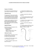
6.1 Liquid Calibration and the Calibration Filter
The AF21/AF22 incorporates a calibration filter that has been characterized to the process variable, i.e.
APHA, Saybolt, Hazen Color etc. The calibration filter actuator is located on the detector endplate and is
slotted for a small blade screwdriver. A lock set screw is located on the endplate. A clock-wise rotation of
the actuator places the Calibration Filter in the optical path of the detector which simulates an optical
absorbance, which has been set against a known liquid standard. This Cal Filter value is included on the
instrument’s test sheet. The Cal Filter is intended as a “working standard” and is not a liquid standard
replacement. A liquid calibration procedure is included as an addendum to this manual. See figure 14.
Optional
Air Purge
Detector
Connector
Cal Filter
Actuator
CW- Cal Filter in PLaceCCW- Process
Actuator Lock
Set Screw
Figure 10 – Calibration Filter Control Actuator
Page 11

Model 682 Dual Beam Photometer AF21/AF22 Inline Sensor Rev. 5 July 13, 2005
5.0 Start Up
5.1 Initial Start-Up
To start up the instrument, follow the steps detailed below:
1. Check in sensor installation wiring and sample line connection.
2. Connect power to the transmitters and leave for at least 30 minutes to warm-up the sensor.
3. Fill the sensor sample cell with a ‘ZERO’ color solution.
4. Select position “A” on each transmitter front panel Range Select switch.
5. Set the front panel “Optical Zero” control to 5.0 (midrange).
6. Adjust the rear panel "Zero Balance” control (coarse) for a reading of 0.0 ± 0.5% on the front panel
display.
7. Adjust the front panel “Optical Zero” control (fine) for a reading of 0.0 % on the front panel display.
Zero
Sensor I/O
Input Power
Transmitter I/O
L1
L2
G
Span
4-20mA
115 VAC
230 VAC
22
23
25
24
21
27
26
To Detector
To AC
Pow er
29
28
To Lamp
21
22
23
24
25
26
27
28
29
Lamp
Fail
1
2
3
4
5
6
7
8
9
10
11
12
13
14
15
Zero
Balance
0-2VDC
4-20mA
Common
Track
Alarm
Figure 11 – Model 682 Rear Panel View
5. Connect an accurate multi-meter to the Analog 4 to 20mA output (Terminals 3 and 4), in series with a
250 ohm load. The 250 ohm load is only necessary if the instrument is not connected to any other
device.
6. Adjust the 4 to 20mA Zero control located on the rear panel to give a 4.00mA reading on the multi-
meter.
7. Drain the sample cell and fill with a high concentration color solution.
8. Adjust the Cal on for a corresponding value on the front DVM of the color standard.
9. Adjust the 4-20mA Span control for a corresponding value (4-20mA) on the multimeter.
Refer to the Calibration Standards section for various color standards solution calibration.
5.2 Using the Fast/Slow Response Feature
The response switch is used to introduce some filtering to the optical density measurement where the
process stream is “noisy” and causing the reading to be a little unstable. The “Fast” position should
Page 12

Model 682 Dual Beam Photometer AF21/AF22 Inline Sensor Rev. 5 July 13, 2005
always be used in preference to the “Slow” position if the reading is acceptable, as this will give the
fastest rise time to changes in VIS absorbance in the process. The “Slow” position will stabilize
readings on the instrument display and analog outputs, but will not be effective in processes where there
is gross interference of the measurement from entrained gas bubbles.
5.3 Adjusting the Alarm Set Point
The Model 682 Dual Beam Photometer is equipped with an alarm front panel indicator and relay output.
When the alarm set point is exceeded, the indicator illuminates and the relay is activated. To set the
alarm setpoint, switch the Meter Switch on the transmitter front panel to “Alarm”. The front panel
display will then show the current value of the alarm set point in OD/%. Change this set point by
adjusting the Alarm adjustment control on the front panel with a terminal screwdriver or similar.
Remember to put the Meter Switch back to “OD” when finished.
5.4 Putting the Unit into Operation
Once the initial start-up checks and adjustments have been made, the unit is fully ready to read color of
liquid in the sensor flow cell. Check the following:
• Select the required range on the transmitter front panel Range Select switch (Suggest ‘A’ position).
• Set the transmitter front panel Meter Switch in the “OD” position.
• Set the transmitter front panel Response Switch to the desired position.
Page 13

Model 682 Dual Beam Photometer AF21/AF22 Inline Sensor Rev. 5 July 13, 2005
6.0 Model 682 Transmitter and Sensor Maintenance
6.1 Model 682 Transmitter
Once the unit is in operation, there is no requirement to access the interior of the Model 682 Dual Beam
Photometer housing for normal day to day operation and calibration.
The procedures described in this section should only be carried out by qualified maintenance
staff.
6.1.1 Accessing the Interior of the Model 682 Instrument
Before opening up the instrument case, REMOVE POWER TO THE INSTRUMENT. Inside the
instrument there are two circuit boards, the Main Board affixed to the left-hand side panel and the Power
Supply Board affixed to the right. Remove the front panel and rear panel screws on the right side of the
module only (as viewed from the front). Fold out the right hand side panel and remove the top and
bottom panels. Take care not to damage the interconnecting cables between the two circuit boards.
Figure 12 – Model 682 Enclosure Access
6.1.2 AC Input Voltage Selection
AC input Voltage is selected by switch on the Power Supply Board. See figure 13 for the Power Supply
Board layout and position of the selector switch. Use a small screwdriver to rotate the switch to the
desired position. When changing the input power voltage, it is necessary to change the fuse to the
correct rating. Always disconnect the power source before attempting any servicing.
6.1.3 Fuse Replacement
The instrument's fuse is a plug in type. It is located on the Power Supply Board. See figure 13 for the
Power Supply Board layout and position of the fuse. Always disconnect the power source before
attempting any servicing.
Page 14

Model 682 Dual Beam Photometer AF21/AF22 Inline Sensor Rev. 5 July 13, 2005
C10
C2
1
2
3
4
5
6
7
8
9
10
LAMP REG
18-36V IN
U2
K1
JP8
D5
R5
D6D4
Q1
REV 4MADE IN USA
GND1
F1
R3
S1
U1
L1
C7 C5
C4
L2
JP6
D3
T1
7
8
6
5
3
4
2
1
C3
D7
+
-
AC
AC
D1
C8
JP4
JP5
JP3
C6
TP2
LAMP ADJ.
+24V
SN
LOT
GND
ISO COM
+15
-15
1
3
D2
R6
C9
JP2
JP1
110
220
Fuse
Input Voltage Selector
115 vac 160 mA
230 vac 80 mA
24vdc 500 mA
(See Replacement
Parts list)
Power Input Sensor Cable Input
Figure 13 – Model 682 Power Supply Fuse and Voltage Select Location
Blown fuses are normally caused by improper voltage selection and/or faulty wiring. Always replace the
fuse with one of the correct rating for the input power supply.
6.1.4 Measurement and Reference Test Voltages
When servicing the sensor, a check of the measurement and reference detector signals is advised. The
test voltages are available on TP8 (Reference) TP9 (Measurement) and TP1 (Common), located on the
main PCB, when JP21/JP22 are selected on pins 2-3. These test voltages should closely match the
values on the test sheet, when the sensor is filled with the “zero” fluid. These test point voltages provide
an accurate measurement of the sensor output. Return JP21/JP22 to the “Run” position, pins 1-2, when
finished testing.
Page 15

Model 682 Dual Beam Photometer AF21/AF22 Inline Sensor Rev. 5 July 13, 2005
U24
C8
C32
C33
TP8
TP1
R93
R81
U5
R65
R67
D2
C6
C5
D1
R29
R50
R38 U19
R64
R84
R89
R90
J14 C27
R58
C16
C15
C2
C43
R6
C12
TP7
J15
TP9
R82
C10
C3
R57
U13
C44 D7
R47
R46
C18
C17
U23
K2
JP21
JP20
R79
R56
R77
C42
COM
Q1
C34
C35
C36
D4
C7U11
REV 1, C 1998, MADE IN USA
LOT SER
MODEL 682 COLORIMETER
SPAN
ZERO
OUT
LOG
TO DVM
SIGNAL INPUT
POWER IN
L2
D5
D8
R75
R70
JP18
U12
R54
C9
R59
JP1
R1 C1
SW3
SW1
SW2
JP19
R87
U17
R51
R52
U9
J1
Q2
U22
TP6
JP23
J24
TP5 JP5
SPAN
ZERO
RTD
TO TC
ADJUST
A GAIN
SELECT
SELECT
B GAIN
CAL
ALARM
C4
OPTICAL
ZERO
MEAS
REF
CUS SPAN
1
23
1
2
3
1-2 TC
2-3 NOR
ABS
JP23 1-2 CUS
JP23 2-3 NOR
GAIN
1
2
3
1
2
3
RUN
RUN
TEST
TEST
IN TEST MEAS/REF CHANNELS
1 VDC OUT PER 1uA INPUT
A-B GAIN SELECT
RESPONSE
ALARM/PROCESS SELECT
DP1
DP2
DP3
SELECT DP IN
CUSTOM SPAN
DP1 NORMAL
4-20 MA ADJ
U10
12345 54321
LOG 100
A-B GAIN SELECT, J1
JUMPER GAIN
AD620
REF200
JP21 AND JP22 SELECT
THE TEST/RUN MODE FOR
SENSOR SETUP.
THE DEFAULT MODE IS 'RUN'.
1-2 JUMPED ON JP21/22
OPEN X 1
5 X 2.5
4 X 5
3 X 10
2 X 20
1 X 50
Figure 14 – Model 682 Main PCB Jumper Locations
Page 16
/