Craftsman 358.348340 Owner's manual
- Category
- Grass trimmers
- Type
- Owner's manual
This manual is also suitable for

358.348340
Instruction Manual
English
Manuel d'instructions
Franqais
Bedienungsanweisung
Deutsch
Manual de instrucciones
Espahol
Libretto d'lstruzioni
Italiano
Please read these instructions carefully and make
sure you understand them before using this unit.
Avant d'uti]iser cet appareil, veuil]ez lire attentive-
ment les instructions et assurez-vous de les avoir
comprises.
Lesen Sie diese Hinweise zur Handhabung des
Ger_ts aufmerksam dutch. Verwenden Sie es
erst, wenn Sie sicher sind, dab Sie alle Anweisun-
gen verstanden haben.
Lea atentamente las instrucciones y asegt_rese de
entenderlas antes de utilizar este unidad.
Leggere attentamente queste istruzioni e accertar-
si di avede comprese prima di usare I'unit&.
Handleiding Lees deze instructies zorgvuldig en wees er zeker
Nederlands van dat u ze begrijpt alvorens dit apparaat te ge-
bruiken.
(E 530164555 1/1/04

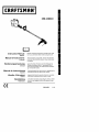
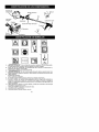
Fueltank
\
ON/OFF
Switch
Starter
Handle
Primer Bulb
Assist handle
J
Throttle
Assist handle adjustment
Tube
Shield
Wrench
anual
Trimmer head
/
/
6 i
i
K
e_
A. WARNING! This trimmer can be dangerous! Careless or improper use can cause
sebous or even fatal injury.
B. Read and understand the instruction manual before using the trimmer.
C. Never use blades with this tool.
D. WARNING! The trimmer line can throw objects violently. You can be blinded or
injured. Always wear eye protection.
E. Always use:
Ear protection
Protective glasses or visor
F. Assist handle to be positioned only below the arrow.
G. The operator of the machine must insure that no one comes within a 15 meter radius
while worki ng. When several operators are worki ng within the same area a safety dis-
tance of at least 15 meters must be observed.
H. Use unleaded or quality leaded petrol and two-stroke oil mixed at a ratio of 2.5%.
I. EngineON/OFF Switch.
J. Sound powerlevel
K. Max speed of output axle, rpm

_IWARNING: When using gardening
appliances, basic safety precautions should al-
ways be followed to reduce the risk of fire and
serious injury. Read and follow all instructions.
This power unit can be dangerous! Operator is
responsible for fcllowing instrucflons and warn-
ings on unit and in manual Read entire instruc-
tion manual before using unit! Be thoroughly fa-
miliar with the controls and the proper use of the
unit. Restrict the use of this unit to persons who
read, understand, and fotlow instructions and
warnings on unit and in manual. Never allow
children to operate this unit.
INSTRUCTION SAFETY INFORMATION
MANUAL ON THE UNIT
_lb DANGER: Never use blades, wire, or
flailing devices. This unit is designed for line
th miner use only. Use of any other accessories
or attachments will increase the risk of injury.
@©O
4_IWARNING: Trimmer line throws ob-
jects violently. You and others ca n be blinded/
injured. Wear safety glasses and leg protec-
tion. Keep body parts clear of rotating line.
Safety Glasses or similar eye protection
Keep children, bystanders, and animals 15 me-
ters away. If approached stop unit immediately.
If situations occur which are not covered in
this manual, use care and good judgement. If
you need assistance, contact your authorized
service dealer.
OPERATOR SAFETY
• Dress properly. Atways wear safety
glasses or similar eye protection when op-
erating, or performing maintenance, on
your unit (safety gtasses are available).
Eye protection should be marked Z87.
• Always wear face or dust mask if operation
is dusty.
• Always wear heavy, long pants, long
sleeves, boots, and gloves. WeN ring safety
leg guards is recommended.
• Always wear foot protection. Do not go
barefoot or wear sandals. Stay clear of
spinning line.
• Secure hair above shoulder length. Secure
or remove loose clothing or clothing with
loosely hanging ties, straps, tassels, etc.
They can be caught in moving parts.
• Being fully covered also helps protect you
from debris and pieces of toxic plants
thrown by spinning line.
• Stay Alert. Do not operate this unit when you
are tired, ill, upset or under the influence of aF
cobel, drugs, or medication. Watch what you
are doing; use common sense.
• Wear hearing protection.
• Never start or run inside a closed room or
building. Breathing exhaust fumes can kill.
• Keep handles free of oil and fuel.
UNIT / MAINTENANCE SAFETY
• Disconnect the spark plug before performing
maintenance except carburetor adjustments.
• Look for and replace damaged or loose
parts before each use. Look for and repair
fuel leaks before use. Keepin goodworking
condition.
• Replace trimmer head parts that are
chipped, cracked, broken, or damaged in
any other way before using the unit.
• Maintain unit according to recommended
procedures. Keep cutting line at proper
length.
• Use only 2 mm diameter Craftsman@ brand
line. Never use wire, rope, string, etc.
• thstall required shield properly before usthg
the unit. Use only specified trimmer head;
make sure it is properly installed and se-
curely fastened.
• Make sure unit is assembled correctly as
shown in this manual.
• Make carburetor adjustments with lower
end supported to prevent line from contact-
ing any object.
• Keep others away when makthg carburetor
adjustments.
• Use only recommended Craftsman@ ac-
cessories and replacement parts.
• Have all maintenance and service not ex-
plained in this manual performed by an au-
thorized service dealer.
FUEL SAFETY
• Mix and pour fuel outdoors.
• Keep away from sparks or flames.
• Use a container approved for fuel.
• Do not smoke or allow smoking near fuel or
the unit.
• Avoid spilling fuel or oil Wipe up all fuel spills.
• Move at least 3 meters away from fueling
site before starting engine.
• Stop engine and allow to cool before re-
moving fuel cap.
• Always store gasoline in a container ap-
proved for flammable liquids.

CUTTING SAFETY
_kWARNING: Inspect the area before
each use. Remove objects (rocks, broken
gblaSs,nails, wire, etc.) which can be thrown
y or become entang(ed in line. Hard objects
can damage the trimmer head and be thrown
causing serious injury.
• Use only for trimming, scalping, mowing
and sweeping. Do not use for edging, prun-
ing or hedge trimming.
• Keep firm footing and balance. Do not over-
reach.
• KeepalJ partsofyour bodyawayfrommuf-
tier and spinning line. Keep engine below
waist levek A hot muffler can cause serious
burns.
• Cut from your right to your left. Cutting on
left side of the shield will throw debris away
from the operato£
• Use only in daylight or good artificial light.
• Use only for jobs explained in this manual.
TRANSPORTING AND STORAGE
• Allow the engine to cool; secure unit before
storing or transporting in vehicle.
• Empty fuel tank before stodng or transport-
ing the unit. Use up fuel left in the carburetor
by starting engine and letting it run until it
stops.
• Store unit and fue( in an area where fuel va-
pors cannot reach sparks or open flames
from water heaters, e(ectric motors or
switches, furnaces, etc.
• Store unit so line (imiter cannot accidental(y
cause injury. Unit can be hung by the tube.
• Store the unit out of the reach of children
SPECIAL NOTICE: Exposure to v(bra-
tions through pro(onged use of gasoline pow-
ered hand tools cou(d cause b(ood vesse( or
nerve damage in the fingers, hands, and
joints of people prone to circulation disorders
or abnormal swellings. Prolonged use in cold
weather has been linked to b(ood vessel dam-
age in otherwise healthy people. If symptoms
occur such as numbness, pain, loss of
strength, change in skin color or texture, or
(oss of feeling in the fingers, hands, or joints,
discontinue the use of this tool and seek med-
ical attention. An anti-vibration system does
not guarantee the avoidance of these prob-
lems. Users who operate power tools on a
continual and regular basis must monitor
close(y their physical condition and the condi-
tion of this tool.
WARNING: Make sure unit is proper-
ly assembled and all fasteners are secure.
CARTON CONTENTS
Check carton contents against the following
(ist:
Model 358.348340
• Trimmer
• Shield
• Wrench for shield assembly
• 2-cycle engine oil
• Extra spool
Examine parts for damage. Do not use dam-
aged parts.
It is normal for the fuel filter to rattle in the
empty fuel tank.
Finding fuel or oil residue on muffler is normal
due to carburetor adjustments and testing
done by the manufacture£
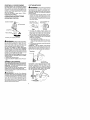
ADJUSTING THE HANDLE
_kI,WARNING: When adjusting the han-
dle, be sure it remains below the safety label.
Assist handle must be positioned only be(ow
the arrow.
1. Loosen wing nut on handle.
2. Rotatethehandieonthetubetoan upright
position; retighten wing nut.
ATTACHING THE SHIELD
WARNING: The shield must be prop-
erly installed. The shield provides partial
protection from the risk of thrown objects to
the operator and others and is equipped with
a line limiter which cuts excess line. The line
limiter (on underside of shield) is sharp and
can cut you.
1. Remove nut and washer from bolt.
2. Assemble parts as shown in illustration.
3. Tighten nut securely with wrench (pro_
vided).
washer and nut Washer
from this bolt;
use for assembling
shield.

ZIL...__....._
4_WAI_NIN{J: Be sure to read the fuel
information in the safety rules before you be-
gin. If you do not understand the safety rules,
do not attempt to fuel your unit. Contact an
authobzed service dealer.
FUELING ENGINE
,_WARNING: Remove fuel cap slowly
when refueling.
This engine is certified to operate on un-
leaded gasoline. Before operation, gasoline
must be mixed with a good quality 2-cycle air-
cooled engine oil. We recommend Crafts_
man® brand oil mixed at a ratio of 40:1
(2.5%). A 40:1 ratio is obtained by mixing 4
liters of unleaded gasoline with 95 ml of oil.
DO NOT USE automotive oil or boat oil.
These oils will cause engine damage. When
mixing fuel, follow instructions printed on o11
container. Once oil is added to gasolk/e,
shake container momentarily to assure that
thefuel is thoroughlymixed. Always readand
follow the safety rules relating to fuel before
fueling your unit.
IMPORTANT
Experience indicates that alcohol blended
fuels (called gasohot or using ethanol or
methanol) can attract moisture which leads to
separation and formation of acids dudng stor-
age. Acidic gas can damage the fuel system
of an engine while in storage. To avoid engine
problems, empty the fuel system before stor-
age for 30 days or longer. Drain the gas tank,
start the engine and let itrun until the fuel lines
and carburetor are empty. Use fresh fuel next
season. Never use engine or carburetor
cleaner prod ucts in the fuel tank or permanent
damage may occul_
HOW TO STOP YOUR UNIT
• To stop the engine, move the ON/OFF
switch to the OFF position.
HOW TO START YOUR UNIT
_WARNING: The trimmer head will
turn while starting the engine. Avoid any con-
tact with the muffler. A hot muffler can cause
serious burrs.
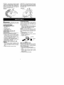
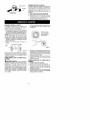
STARTING A COLD ENGINE (or a
warm engine after running out of fuel)
Starting Position
1. Set unit on a flat surface.
2. Move ON/OFF switch to the ON position.
3. Slowly press the primer bulb 6 times.
4. Move choke lever to FULL CHOKE position.
Starter Handle
Choke
Lever
Muffler
5. Squeeze and hold trigger through at/re-
maining steps.
6. Pull starter rope handle sharply until en-
gine sounds as if it is trying to start, but do
not pull rope more than 6 times.
7. As soon as engine sounds as if it is trying
to start, move choke lever to HALF
CHOKE.
8. Pull starter rope sharply until engine runs,
but no more than 6 pulls. If the engine
doesn't start after 6 pulls (at the HALF
CHOKE position), move the choke lever to
the FULL CHOKE position and press the
primer bulb 6 times. Squeeze and hold the
throttle trigger and pull the starter rope 2
more times. Move the choke lever to the
HALF CHOKE position and pull the starter
rope until the engine runs, but no more
than 6 pulls.
NOTE: If engine still doesn't start, it is
probably flooded. Proceed to STARTING
A FLOODED ENGINE.
9. Once the engine starts, allow it to run 10
seconds, then move the choke lever to
OFF CHOKE. Allow the unit to run for 30
more seconds at OFF CHOKE before re-
leasing the throttle trigger.
NOTE: If engine dies with the choke lever
in the OFF CHOKE position, move the
choke lever to the HALF CHOKE position
and pull the rope until engine runs, but no
more than 6 pulls.
STARTING A WARM ENGINE
1. Move ON/OFF switch to the ON position.
2. Move the choke lever to the HALF
CHOKE position.
3. Squeeze and hold the throttle trigger.
Keep throttle trigger fully squeezed until
the engine runs smoothly.
4. Pull starter rope sharply until engine runs,
but no more than 5 pulls.
5. Allow engine to run 15 seconds, then
move the choke lever to the OFF CHOKE
position.
NOTE: If engine has not started, pull starter
rope 5 more pulls. If engine still does not ru n,it
is probably flooded.

STARTING A FLOODED ENGINE
Flooded engines can be started by placing
the choke lever in the OFF CHOKE position;
then, pull the rope to clear the engine of ex-
cess fuel This could require pulling the starter
handle many times depending on how badly
the unit is flooded.
If the unit still doesn't start, refer to TROU-
BLESHOOTING TABLE.
OPERATING INSTRUCTIONS
OPERATING POSITION
ALWAYS WE_ - _eEye Protecbon
Long Pantas._/i
Heavy Shoe
Cut from your right to your left.
_k WARNING: Always wear eye protec-
tion and hearing protection. Never tean over
the trimmer head. Rocks or debris can rico-
chet or be thrown into eyes and face and
cause blindness or other serious injury.
Do not run the engine at a higher speed than
necessary. The cutting line will cut efficiently
when the engine is run at less than full throttle.
At lower speeds, there is less engine noise and
vibration. The cutting line will last longer and wilt
be less likely to "weld" onto the spool.
Always release the throttle trigger and allow the
engine to return to idle speed when not cutting.
To stop engine:
Release the throttle trigger.
Move the ON/OFF switch to the OFF posi-
tion.
TRIMMER LINE ADVANCE
The cutting head advances line automati-
cally. Do not tap head on the ground to ad-
vance line. This may break parts and cause
cutting head to malfunction.
Upon unit start up, the line will advance auto-
maflcally to the correct cutting path length.
Always keep the shield in place when the tool
is being operated.
_WARNING: Use only 2 mm diameter
round line. Other sizes and shapes of line will
not advance properly and will result in improp-
er cutting head function or can cause serious
injury. Do not use other materials such as
wire, string, rope, etc. Wire can break off dur-
ing cutting and become a dangerous missile
that can cause serious injury.
CUTTING METHODS
_k WARNING: Use minimum speed and
do not crowd the line when cutting around
hard objects (rock, gravel, fence posts,etc.),
which can damage thetrimmer head, become
entangled in the line, or be thrown causing a
serious hazard.
• The tip ofthe line does the cutting. You will
achieve the best performance and mini-
mum line wear by notcrowding the line into
the cutting area. The right andwrong ways
are shown below.
Tip of the Line Line Crowded into
Does The Cutting Work Area
Right Wrong
• The line will easily remove grass and
weeds from around wails, fences, trees and
flower beds, but it also can cut the tender
bark of trees or shrubs and scar fences.
• For trimming or scalping, use less than full
throttle to increase line life and decrease
head wear, especially:
** During light duty cutting.
Near objects around which the line can-
wrap such as small posts, trees or fence
wire.
• For mowing or sweeping, use full throttle for
a good clean job.
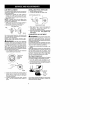
TRIMMING - Hold the bottom of the trimmer
head about 80 mm above the ground and at an
angle. Allow only the tip of the line to make con-
tact. Do not force trimmer line into work area.
3 in. (8 cm)
Above Ground
SCALPING - The scalping technique removes
unwanted vegetation. Hold the bottom of the
trimmer head about 80 mm above the ground
and at an angle. Allow the tip of the line to strike
the ground around trees, posts, monuments,
etc. This technique increases line wear.
Scalping

MOWING - Your trimmer is ideal for mowing
in places conventional lawn mowers cannot
reach. In the mowing position, keep the line
parallel to the ground. Avoid pressing the
head into the ground as this can scalp the
ground and damage the tool.
Mowing
÷S
SWEEPING - The fanning action of the rotat-
ing fine can be used for a quick and easy
clean up. Keep the line parallel to and above
the surfaces being swept and move the tool
from side to side.
IIL
_IbWARNING: Disconnect the spark
plug before performing maintenance except
for carburetor adjustments.
CHECK FOR LOOSE
FASTENERS AND PARTS
• Spark Plug Soot
• Air Filter
• Housing Screws
• Assist Handle Screw
• Debris Shield
CHECK FOR DAMAGED OR
WORN PARTS
Contact an authorized service dealer for re-
placement of damaged or worn parts.
• ON/OFF Switch ~ Ensure ON/OFF switch
functions properly by moving the switch to
the OFF position. Make sure engine stops;
then restart engine and continue.
• Fuel Tank - Discontinue use of unit if fuel
tank shows signs of damage or leaks.
• Debris Shield - Discontinue use of unit if
debris shield is damaged.
INSPECT AND CLEAN UNIT AND
LABELS
• After each use, inspect complete unit for
loose or damaged parts. C]ean the unit and
labels using a damp cloth with a mild deter-
gent.
• Wipe off unit with a clean dry cloth.
CLEAN AIR FILTER
A dirty air filter decreases engine perform-
ance and increases fuel consumption and
harmful emissions. Atways ctean after every
5 hours of operation.
1. Clean the cover and the area around it to
keep dirt from falling into the carburetor
chamber when the cover is removed.
2. Remove parts as illustrated.
NOTE: Do not clean filter in gasoline orother
flammable solvent to avoid creating a fire haz-
ard or producing harmful evaporative emis-
sions.
3. Wash the filter in soap and water.
4. Allow filter to dry.
5. Add a few drops of oil to the filter; squeeze
the filter to distribute oil
6. Replace parts.
_Filter
_ Screws
Cover
REPLACE SPARK PLUG
Replace the spark plug each year to ensure
the engine starts easier and runs better. Set
spark plug gap at 0,6 mm. Ignition timing is
fixed and nonadjustable.
1. Twist, then pull off spark plug boot.
2. Remove spark plug from cylinder and dis-
card.
3. Replace with Champion RCJ-6Y spark
plug and tighten securely with a 19 mm
socket wrench.
4. Reinstall the spark plug boot.

LINE REPLACEMENT
Pre-wound spools offer the most convenient
method for replacing line and ensuring opti-
mum performance.
• Replacement spools are color-coded to
ensure use of the correct spoot with your
unit. Be su re to use the same color spool as
the existing spool.
NOTE: Always clear dirt and debris from
cutting head components when performing
any type of maintenance.
• Hold spool and unscrew cap by turning in
the direction shown on top of the cap.
• Remove line guide ring and spool.
Cap Line guide ring
Use a pre-wound spool or refill spool with
line. If using a pre-wound spoot, remove tape
strip from line and spool.
REFILLING THE SPOOL WITH LINE
_II_WARNING: Use only 2 mm diameter
round line. Other sizes and shapes of line will
not advance properly and will result in improp-
er cutting head function or can cause serious
injury. Do not use other materials such as
wire, string, rope, etc. Wire can break off dur-
ing cutting and become a dangerous missile
that can cause serious injury.
1. Cut a length of 8 meters of 2 mm diameter
round Craftsman@ brand line.
=_!_!., Feed line in
. _i\ showndirectionon
spoo,.
\
Spool
2. Insert one end of line into center cavity of
empty spool. Ensure line will feed into
spool in the direction shown on the spool
(counterclockwise).
3. Continue feeding line into spool, leaving
100 - t50 mm unwound from center of
spool.
INSTALLING SPOOL WITH LINE
1. Install replacement spooL
2. Thread line through line guide ring.
Line through guide ring
Slot.
A
/
Replacement Spool
3. Rest guide ring on spool and place line
through slot. Allow line to extend 100 -
150 m m from center of spool.
4. Ensure line remains in slot while screwing
cap on to the shaft. Only tighten cap
hand tight!
CARBURETOR ADJUSTMENT
,_IkWARNING: Keep others away when
making idle speed edjustments. Thetrimmer
head will be spinning during this procedure.
Wear your protective eq uipment and observe
all safety precautions.
The carburetor has been carefully set at the
factory. Adjustments may be necessary if you
notice any of the following conditions:
• Engine will not idle when the throttle is re-
leased.
Make adjustments with the unit supported so
the cutting attachment is off the ground and
will not make contact with any object. Hold
the unit by hand while running and making ed-
justments. Keep all parts of your body away
from the cutting attachment and muffler.
Idle Speed Adjustment
Allow engine to idle. Adjust speed until engine
runs without stalling (idle speed too slow).
• Turn idle speed screw clockwise to in-
crease engine speed if engine stalls or dies.
• Turn idle speed screw counterclockwise to
decrease engine speed.
I_dleSpeed
Screw
Air Filter
Cover
If you require further assistance or are unsure
about performing this procedure, contact an
authorized service dealer.

z&
,ttWARNING: Perform the following
steps after each use:
• Allow enginetocool beforestoring or trans-
porting.
• Store unit and fuel in a well ventilated area
where fuel vapors cannot reach sparks or
open flames from water heaters, electric
motors or switches, furnaces, etc.
• Empty fuel tank before storing or transport-
ing the unit.
• Store unit and fuel well out of the reach of
children.
• Store unit with all guards in place. Position
unit so that any sharp object cannot acci-
dentally cause injury.
SEASONAL STORAGE
Prepare unit for storage at end of season or if
it will not be used for 30 days or more.
Lfyour u_it is tQ be stored fQr a period of time:
• Clean the entire unit before lengthy stor-
age.
• Store k_a clean dry area.
• Lightly oil external metal surfaces,
ENGINE
• Remove spark plug and pour I teaspoon of
40:1,2-cycle engine oH(air cooled through
the spark p{ug opening. Slowly pul_the
starter rope 8 to 10times to distribute oil.
• Replace spark plug with newone of recom-
mended type and heat range.
• Clean air filter.
• Check entire unit for loose screws, nuts,
and bolts. Replace any damaged, broken,
or worn parts.
• At the beginning of the next season, use
only fresh fuethaving theproper gasoline to
oil ratio.
OTHER
• Do not store gasoline from one season to
another
• RepJaceyourgasoJineoan if it starts torust.

TROUBLESHOOTING TABLE
_k WARNING: Always stop unit and disconnect spark plug before performing all of the
recommended remedies below except remedies that require operation of the unit.
TROUBLE
Engine will not
start.
CAUSE
1. ON/OFF switch in OFF
position.
2. Engine flooded.
3. Fuel tank empty.
4. Spark plug not firing.
5. Fuel not reaching
carburetor
REMEDY
1. Move ON/OFF switch to ON position.
2. See "Starting a Flooded Engine" in
Operation Section.
3. Fill tank with correct fuel mixture.
4. Install new spark plug.
5. Check for dirty fuel filter; replace.
Check for kinked or split fuel line;
repair or replace.
6. Contact an authobzed service dealer.
6. Carburetor requires
adjustment.
Engine will 1. Carburetor requires 1. See "Carburetor Adjustmenf' in
not idle adjustment. Service and Adjustments Section.
properly. 2. Crankshaft seals worn. 2. Contact an authorized service dealer.
3. Compression low. 3. Contact an authobzed service dealer.
Engine will not 1. Air filter dirty. 1. Clean or replace air filter.
accelerate, 2. Spark plug fouled. 2. Clean or replace plug
lacks power, and regap.
or dies under 3. Carburetor requires 3. Contact an authorized service dealer.
a load. adjustment.
4. Carbon build-up on 4. Contact an authorized service dealer.
muffler outlet screen.
5. Compression low. 5. Contact an authobzed service dealer.
Engine 1. Choke partially on. 1. Adjust choke.
smokes 2. Fuel mixture incorrect. 2. Empty fuel tank and refill with
9xcessively. correct fuel mixture.
3. Air filter dirty. 3. Clean or replace air filter.
4. Carburetor requires 4. Contact an authorized service dealer.
adjustment.
Engine runs 1. Fuel mixture incorrect. I. Empty fuel tank and refill with
hot. correct fuel mixture.
2. Spark plug incorrect. 2. Replace with correct spark plug.
3. Carburetor requires 3. Contact an authorized service dealer.
adjustment.
4. Carbon build-up on 4. Contact an authorized service dealer.
muffler outlet screen.
EU Declaration of Conformity relating to 2000/14/E0
We, Electrolux Home Products, Inc,, Texarkana, TX, 75501, USA, T6]. : +1 903 223
4100, declare under sole responsibility that the Craftsman model 358.348340 grass
trimmer was assessed in accordance with Annex V of the DIRECTIVE and from serial
numbers 2002-115N00001 and onwards, conforms to the provisions of the DIRECTIVE.
The cutting width is 431 m m. The measured sound power is 106,6 d B and the guaranteed
sound power is 112 dB.
Texarkana 02-04-25 _ _._
Michael S. Sounds, Director
Product Safety and Standards
10

EC Declaration of Conformity (Directive 98/37/EC, Annex tl, A) (Only applies to
Europe)
We, Electrolux Home Products, Inc., Texarkana, TX, 75501, USA, T_I. : +1 903 223
4100, Declare under sole responsibility that grass trimmer Craftsman 358.348348 from
serial numbers 2002-It5N00001 and onwards, follows the provisions of the
DIRECTIVES: 98/37/EC (machinery) and 8g/336/EEC (electromagnetic compatibility),
including amendments and is in conformity with the following standards: EN 292-2, EN
ISO 11806 and ClSPR 12.
SMP, The Swedish Machinery Testing Institute, Fyrisborgsgatan 3 S-754 50 Uppsala,
Sweden, has carried out voluntary type approval The certificate(s) are numbered:
HT e,CC 22020495 2
Michae{ S. Hounds, Director
Product Safety and Standards
MODEL: Craftsman 358.348340
ENGINE
Displacement, cm 3 25
Maximum engine power, measured in
accordance with ISO 8893_ kW 0_7
ENGINE ROTATIONAL SPEEDS
At maximum engine power 8000
Recommended maximum speed 8000
Recommended speed idling 4000
FUEL AND LUBRICATION SYSTEM
Fuel tank volume capacity, cm 3 340
Fuel consumption at maximum engine power,
measured in accordance with _SO 8893, g/h 313
Specified fuel consumption at max. engine power,
measured in accordance with ISO 8893, g/kWh 782
WEIGHT
Without cutting attachment or shield, empty tank, kg 3_7
CUTTING ATTACHMENT
Wound spool, part number #71-85843
Line guide, part number #530403949
Cap assembly, part number #530054223
NOISE LEVELS (Octave Band Analysis 1O9-f0OOOhz 1!3 Octave)
SOUND PRESSURE LEVELS measured in accordance with ISO 7917
Idling, dB(A) 78
Racing, dB (A) 96
SOUND POWER LEVELS measured in accordance with ISO 10884
Idling. dB(A) 91
Racing, dB(A) 106
VIBRATION LEVELS measured in accordance with ISO 7916
FRONT HANDLE
Idling, m/s 2 4,8
Racing, m/s 2 1I ,3
REAR HANDLE
Idling, m/s 2 3,0
Racing, m/s 2 7,4
YEAR OF CONSTRUCTION: 2004
MANUFACTURER'S ADDRESS: Sears, Roebuck and Co.
3333 Beverly Road
Hoffman Estates, IL 60179
1I
Page is loading ...
Page is loading ...
Page is loading ...
Page is loading ...
Page is loading ...
Page is loading ...
Page is loading ...
Page is loading ...
Page is loading ...
Page is loading ...
Page is loading ...
Page is loading ...
-
 1
1
-
 2
2
-
 3
3
-
 4
4
-
 5
5
-
 6
6
-
 7
7
-
 8
8
-
 9
9
-
 10
10
-
 11
11
-
 12
12
-
 13
13
-
 14
14
-
 15
15
-
 16
16
-
 17
17
-
 18
18
-
 19
19
-
 20
20
-
 21
21
-
 22
22
-
 23
23


Craftsman 358.348340 Owner's manual
- Category
- Grass trimmers
- Type
- Owner's manual
- This manual is also suitable for
Ask a question and I''ll find the answer in the document
Finding information in a document is now easier with AI
in other languages
Related papers
-
Craftsman 358.348321 Owner's manual
-
-
-
-
-
-
-
-
-
Other documents
-
McCulloch TrimMac 250 25cc User manual
-
Poulan 545154718 User manual
-
Weed Eater TWIST-N-EDGE TE500CXL User manual
-
Poulan 530163414 User manual
-
-
Sears FL20 User manual
-
MC CULLOCH Trim Mac SL User manual
-
Poulan 545154718 User manual
-
-