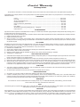
United States Stove VG900 Owner's manual
- Category
- Fireplaces
- Type
- Owner's manual

Model VG900
THERMOSTAT CONTROLLED CIRCULATOR SERIES
SAFETY NOTICE:
If this heater is not properly installed, a house re may result. To reduce the risk of re, follow
the installation instructions. Contact local building or re ofcials about permits, restrictions
and inspection requirements in your area.
• ASSEMBLY
• INSTALLATION
• OPERATION
• REPAIR PARTS
Conforms To:
UL STD 1482;
ULC STD S627
852083B-0703G
United States Stove Company
227 Industrial Park Rd. Pittsburg, TN 37380
(800) 750-2723 www.usstove.com
CAUTION:
Please read this entire manual before you install and use your new room heater. Failure to
follow instructions may result in property damage, bodily injury, or even death.
DO NOT USE THIS HEATER IN A MOBILE HOME OR TRAILER
COAL ONLY

-2-
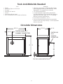
Tools And Materials Needed
Tools
• Pencil
• Measuring Tape or 6 foot rule
• Tin Snips
• Drill and 1/8” dia. bit
• Gloves
• Screwdriver (Blade type)
• 5/16” Nut Driver or 5/16” Socket w/Ratchet
Materials
• Chimney Connection- 6” Diameter Black Steel
pipe (24 gauge minimum) and elbow(s) either
adjustable1 or corrugated as necessary
• 1/2” Sheet Metal Screws
• 6” Inside Diameter Underwriters Laboratories
(UL) listed Residential Type and Building Heating
Appliance Chimney, Type “HT”, or 6” existing
Masonry Chimney with ue liner.
• Floor Protector Material: 3’ x 4’-6”
• Furnace Cement (Manufacturer recommends:
Rutland Code 78 or Equivalent) 1 Avoid adjustable
elbows, they leak!
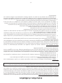
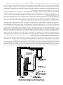
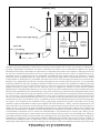
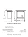
32 1/4
12 1/2
33 1/2
4 1/8
4 1/4
19 1/4
CENTER LINE OF 6"
CHIMNEY CONNECTOR
24
TOP OF FLOOR PROTECTOR
CENTER LINE
OF 6"
CHIMNEY
CONNECTOR
Circulator Dimensions

-3-
Installation And Operation
SAVE THESE INSTRUCTIONS! READ THESE RULES AND THE INSTRUCTIONS CAREFULLY
1. Check local codes. The installation must comply
with their rulings. Do not install this heater in a
mobile home or trailer.
2. Always connect this heater to a chimney or vent
to the outside. Never vent to another room or
inside a building.
3. Do not connect this heater to an aluminum Type
B gas vent. This is not safe and is prohibited by
all codes. This heater requires connection to
approved chimneys: Either a chimney complying
with the requirements for Type HT chimneys in the
Standard for Chimneys. Factory Built, Residential
Type and Building Heating Appliance, UL 103, or
a code approved masonry chimney with a ue
liner, preferably round. A larger masonry ue may
be used, so long as the ue-section diameter is not
greater than 50 sq. in.
4. The chimney portion (whether factor-built or
masonry) must be tall enough to provide sufcient
draft and safe exit of smoke and combustion
products.
5. Be sure that your Chimney is safely constructed
and in good repair. Have the chimney inspected
by the Fire Department or a qualied inspector
(such as a Chimney sweep). Your insurance
company may be able to recommend a qualied
inspector.
6. Inspect chimney connector and chimney twice
monthly during the heating season for any deposit
of creosote or soot which must be removed.
7. Provide air for combustion from outside the house
into the room where the heater is located. If the
intake is not in the same room, air must have free
access to the room.
8. CAST IRON PARTS MUST BE “SEASONED” TO AVOID
CRACKING. BUILD ONLY SMALL FIRES ON FIRST USE.
9. To prevent injury, do not allow anyone to use this
heater who is unfamiliar with the correct operation
of the heater. Do not allow children to use or in
any way operate this heater. Caution: do not
touch the heater until it has cooled. Always wear
gloves when refueling this unit or working with
metal cabinet parts.
10. Keep the ash pit section free of excess ashes. Do
not allow ashes to stack higher than the sides of
the ash pan. Never allow the ashes to contact the
grate.
11. CAUTION: The special paints used on your heater
may give off some smoke while they are curing
during rst few res. Build small res at rst. The
metal used in construction of the heater has a
light coating of oil. This could give off smoke and/
or odors when heater is used for the rst couple of
times. This should disappear after a short period.
Once this burn-off has occurred, it should not
reoccur.
12. CARING FOR PAINTED PARTS- This heater has a
painted outside jacket, which is durable but will
not stand rough handling or abuse. When installing
your heater, use care in handling. Clean with soap
and warm water when heater is not hot. DO NOT
use any harsh chemicals (acids or caustics) or
scouring powder, as these wear and dull the nish.
13. KEEP THE FEED DOOR, ASH DOOR AND CABINET
DOOR CLOSED AT ALL TIMES EXCEPT WHILE TENDING
THE HEATER. KEEP SEALS IN GOOD CONDITION. DO
NOT OVERFIRE THE HEATER. THIS WILL HAPPEN IF THE
FEED DOOR, OR PARTICULARLY THE ASH DOOR, IS
LEFT OPEN DURING OPERATION. UNDER EXTREME
CONDITIONS THIS CAN PRODUCE DANGEROUS
RESULTS. AT A MINIMUM, IT WILL ALLOW THE PAINT
TO DISCOLOR.
14. DO NOT USE the coal bricks that are manufactured
from coal dust and a wax-type binder.
15. Use smoke detectors in the room where your
heater is installed. We recommend installing smoke
detectors in your home if not already installed.
16. DO NOT connect this heater to any air distribution
duct or system.
17. Never use make-shift compromises during the
installation.
18. For further information on using your heater safely,
obtain a copy of the National Fire Protection
Association (NFPA) publication “Using Coal and
Wood Stoves Safely” NFPA No. HS-10-1978. The
address of the NFPA is Battery March Park, Quincy,
MA. 02269.

-4-
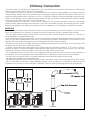
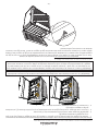
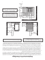
Clearances To Combustible
Minimum clearances to unprotected combustible walls and ceilings as noted by gures 2 through 4 must be
maintained. Drapes, curtains, furniture and other combustible materials should be kept much further away
from the heater to avoid re. If you choose to, you may install the heater and chimney connector closer to
combustible surfaces than indicated by Figures 2 through 4 IF a clearance reduction system is also installed to
protect combustible ceilings and walls near the heater and chimney connector. However, there are limits to how
close the heater and chimney connector can be installed to combustible surfaces protected by a clearance
reduction system.
A correctly installed clearance reduction system protects the combustible surfaces well beyond the sides and
above the top of the heater and beyond the sides and top of the chimney connector pipe.
Two common types of clearance reduction systems use sheet metal with a minimum thickness of 28 gauge
(galvanized steel, aluminum, copper) or a 3-1/2 inch (4 inch nominal) thick masonry wall. Either of these materials
must be spaced out 1 inch from the combustible surfaces. With sheet metal, non-combustible spacers are used
to maintain the 1 inch air space. With a masonry wall, metal wall ties and furring strips, if needed are used to
anchor the brick to the wall. To avoid excessive heat transmission, the spacers or wall ties should not be placed
directly behind the heater or chimney connector. The 1 inch air space provides free air circulation. It is essential
that there be openings at the top and bottom of these clearance reducers so cool air can enter at the bottom
and hot air exit at the top. It is the “chimney effect” whereby when the air in the space is heated, it rises exiting
from the top and being replaced by cooler air at the bottom, that makes these shields effective.
Masonry, or other non-combustible products, attached directly to a combustible surface without an air space
offer very little protection and cannot be considered a clearance reducer unless specied materials have been
tested and listed for direct attachment to a combustible surface. The same applies to thin veneer brick and
stone coverings. These materials provide adequate protection only when mounted on sheet metal with a 1 inch
spacing to the wall.
A variety or prefabricated clearance reduction systems which have been tested and listed are available through
heater dealers. Always look for a safety listing label on the product when selecting a clearance reduction
system and make sure it is designed for solid fuel appliances. The manufactures of these systems provide specic
installation instructions that must be followed exactly for a safe installation.

-5-
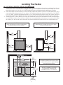
Locating The Heater
AS A LOCATION IS SELECTED, KEEP THE FOLLOWING MIND
1. The chimney connection should be as airtight as possible. The heater must have its own chimney ue. Do not
connect this unit to a chimney ue serving another appliance. If there is no chimney near where you wish to
place the heater, you can use a UL 103HT Residential Type and Building Heating Appliance Chimney.
2. Place the heater on solid masonry or solid concrete. When the heater is used on a combustible oor, use a
non-combustible oor protector of one layer of 3/8" millboard having a thermal conductivity of K=0.84 BTU
in./ft. 2 hr. Deg. F with 28-gauge sheet metal or a UL 1618 Listed oor protector with 0.45 R-Value. Have the
oor protector extend 16" beyond the door side of the heater and under the connector pipe in the back.
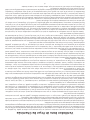
3. Check Figures 2, 3, and 4. Be sure you have the clearances shown from the heater and the connector pipe
to combustible surfaces. If you have a solid brick or stone wall behind your heater, you can place the heater
as close as you wish to the wall. If the wall is only faced with brick or stone, treat it as a combustible wall.
35”
(989mm)
25”
(635mm)
12’
(305mm)
16”
(406mm)
12’
(305mm)
36”
(914mm)
4 3/4”
(121mm)
54”
(1.37M)
25”
(635mm)
17”
(432mm)
NOTE: BEFORE FIRING HEATER
Slide rebricks toward the rear so no gaps
remain between them.
CAUTION:
Keep furnishings and other combustible
materials away from the heater.
Notice:
Clearances stated above may ONLY
be reduced by means approved by
the regulatory authority.
DO NOT CONNECT TO or use
in conjunction with ANY AIR
DISTRIBUTION DUCT OR SYSTEM.

-6-
Two basic types of chimneys are approved for use with solid fuel: Factory-built and masonry. Factory-built
chimney must comply with UL 103 type “HT” standard.
Do not expect your stove or furnace to create draft. Draft is not a function of the appliance. It is purely a function
of the chimney. Modern stoves and furnaces are much more air-tight and efcient than those of the past and,
therefore require greater draft. A minimum of .05 w.c. (12.45Pa), is required for proper drafting to prevent back-
pufng, smoke spillage, and to maximize performance. Gauges to measure chimney draft are readily available
at stove shops and are economical to purchase or rent.
Chimneys perform two functions - one of which is apparent: The chimney provides a means for exhausting
smoke and ue gases resulting from combustion of the fuel. Secondarily, though, the chimney provides “Draft”
which allows oxygen to be continuously introduced into the appliance, so that proper combustion is possible.
IMPORTANT
Your chimney connector and chimney must have the same diameter as the stove outlet (6”). If this is not the
case, we recommend you contact your dealer in order to insure there will be no problem with the draft.
The stove pipe must be made of aluminized or cold roll steel with a minimum thickness of 0.021” or 0.53 mm. It is
strictly forbidden to use galvanized steel.
Your smoke pipe should be assembled in such a way that the male section (crimped end) of the pipe faces
down. This will allow condensation in the ue to run back into the heater. Attach each of the sections to one
another with three equidistant metal screws and seal each joint with furnace cement.
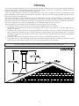
The pipe must be short and straight. All sections installed horizontally must slope at least 1/4 inch per foot, with
the upper end of the section toward the chimney.
To insure a good draft, the total length of the coupling pipe should never exceed 8’ to 10’ (2.4m to 3.04 m).
(Except for cases of vertical installation, cathedral-roof style where the smoke exhaust system can be much
longer and connected without problem to the chimney at the ceiling of the room).
It is recommended that no more than two 90 degree bends be used because it may reduce the amount of
natural draft. The use of corrugated (non-adjustable) elbows is preferred as they are much more airtight.
You must have at least 18 inches of clearance between any horizontal piping and the ceiling.
The pipe cannot extend into the chimney ue.
The chimney connector must not pass through an attic, roof space, closet, any concealed space, oor, ceiling,
wall or combustible construction. Where passage through a wall or partition of combustible construction, the
installation must conform to CAN/CSA-B365, Installation Code for Solid-Fuel-Burning Appliances & Equipment.
To Stove
Chimney Connection

-7-
Your stove may be hooked up with a 6” factory built or masonry chimney. If you are using a factory built chimney,
it must comply with UL 103 standard; therefore it must be a Type HT (2100°F). It is extremely important that it be
installed according to the manufacturer’s specications.
If you are using a masonry chimney, it is important that it be built in compliance with the specications of the
National Building Code. It must be lined with re clay bricks, metal or clay tiles sealed together with re cement.
(Round ues are the most efcient).
The interior diameter of the chimney ue must be identical to the stove smoke exhaust. A ue which is too
small may cause draft problems, while a large ue favours rapid cooling of the gas, and hence the build-up of
creosote and the risk of chimney res. Note that it is the chimney and not the stove which creates the draft effect;
your stove’s performance is directly dependent on an adequate draft from your chimney.
The following recommendations may be useful for the installation of your chimney:
1. It must rise above the roof at least 3’ (0.9m) from the uppermost point of contact.
2. The chimney must exceed any part of the building or other obstruction within a 10’ (3.04m) distance by a
height of 2’ (0.6m).
3. Installation of an interior chimney is always preferable to an exterior chimney. Indeed, the interior chimney
will, by denition, be hotter than an exterior chimney, being heated up by the ambient air in the house.
Therefore the gas which circulates will cool more slowly, thus reducing the build-up of creosote and the risk
of chimney res.
4. The draft caused by the tendency for hot air to rise will be increased with an interior chimney.
5. Using a re screen at the extremity of the chimney requires regular inspection in order to insure that it is not
obstructed thus blocking the draft, and it should be cleaned when used regularly.
Chimney
DO NOT CONNECT THIS UNIT TO A CHIMNEY FLUE SERVING ANOTHER APPLIANCE.

-8-
When a metal prefabricated chimney is used, the manufacturer’s installation instructions must be followed. You
must also purchase (from the same manufacturer) and install the ceiling support package or wall pass-through
and “T” section package, restops (where needed), insulation shield, roof ashing, chimney cap, etc. Maintain
proper clearance to the structure as recommended by the manufacturer. The chimney must be the required
height above the roof or other obstructions for safety and proper draft operation.
Factory Built Chimney

-9-
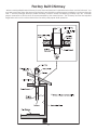
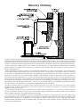
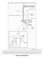
Venting Into A Fireplace
Many people may wish to convert an existing replace to heater use. Usually, safe connection of stovepipe to
a masonry chimney requires more effort than connection to a prefabricated chimney. The replace must be
closed and sealed at the damper in the ue. Good sealants are high temperature caulking, ceramic wool, and
furnace cement. Always remember to inspect the masonry chimney and replace. If necessary, clean the ue
and smoke shelf before beginning your installation. Install the heater into the chimney so that the system can be
dismantled for cleaning and inspection.
Before deciding to convert your replace or existing chimney, keep in mind that older replaces and their
chimneys are unsafe. They must be structurally sound, and the ue liner must be in good condition. Do not use a
chimney if it is unlined (should have a tile clay liner to protect brickwork), have it relined professionally. Clearances
to combustibles are explained in the previous section on masonry chimneys. If you have any questions regarding
the condition of the chimney, consult a qualied engineer, competent mason, certied Chimney Sweep, or
knowledgeable inspector.
Many prefabricated replaces fall into the “zero-clearance replace” category. This is a factory metal replace
with multi-layered construction. It is designed to provide enough insulation and/or air cooling so that the base,
back and sides can be safely placed in close contact with combustible oors and walls. Although many
prefabricated replaces have been tested by nationally recognized organizations for use as replaces, they
have not been tested to accept heaters. In fact, their use as such may void the manufacturer’s warranty.
Steel-lined replaces, on the other hand, can be used with heaters. These units use a 1/4-inch re box liner and
an air chamber in connection with 8 inches of masonry to meet code. They contain all the essential parts of a
replace, rebox, damper, throat, smoke shelf, and smoke chamber. Many of them look exactly like a masonry
replace and must be checked closely for above requirements before installing a coal heater into them.
Another method frequently used by some people is to vent the heater directly into the replace. This does not
meet code since the heater is being vented into another appliance - the replace. This method should not be
attempted because combustion products will deposit and build up in the rebox or replace. Be certain not to
install a hazard in you house. You will void your warranty with this installation.
Connection of the stovepipe directly into the existing masonry chimney over the replace opening is the only
approved method. This installation performs better, yielding easy to clean and inspect for creosote. Before
beginning this type of installation plan carefully; a high degree of skill is required to insure safety.
An entry port for the stovepipe must be cut through the chimney with minimum damage to the re clay liner.
Some involved measurements may be required to locate the ue liner exactly. Before cutting, take time to mark
the size and position of the entry port. Position the entry port so that at least 8 inches of the ue liner remains below
the port.
Keep in mind that wood mantels and combustible trim around the replace must have adequate clearances
from the heater and stovepipe or must be protected in an approved manner. Also, be sure to leave at least
24” clearance between the top of the stovepipe and the combustible ceiling or other combustibles. Placing
the center of the entry port 2 feet below the ceiling will insure proper clearance for 6 inch, 8 inch, and 10 inch
stovepipes. Next, install a re clay (at least 5/8 in. thick) or metal thimble, being sure that the thimble is ush with
the inner ue lining. Secure the thimble in place with refractory mortar. The thimble should be surrounded on all
sides with 8 inches of brickwork (solid masonry units) or 24 inches of stone.
Install the stovepipe as far as possible into the thimble, but not past the inside of the ue lining. There should
be a small air space (approximately 1/2 in.) between the stovepipe and thimble, allowing for expansion of the
stovepipe. Seal this airspace with high-temperature caulking or ceramic wool. Finally, be sure to wire the damper
closed and apply the same sealant you used at the stovepipe and thimble junction.
Do not vent up through the replace opening, regardless of whether the replace opening is closed.

-10-
Masonry Chimney
Masonry Chimneys have several positive attributes: If properly built, they are quite durable, and most homeowners
consider them more attractive perhaps than a non-enclosed factory built chimney. And, if the chimney is located
within the connes of the house (that is, not attached to an exterior wall), its mass alone will store heat longer and
continue to release the heat long after the re has died. Masonry chimneys have many disadvantages though.
Masonry chimneys constructed on an exterior wall are exposed to cold outdoor temperatures, promoting
greater heater loss, higher accumulations of creosote, and reduced draft which leads to poorer heater or
furnace performance.
When considering a masonry chimney, round tiles are preferable to square or rectangular, as round tiles have
much better airow characteristics and are far easier to clean. Unfortunately, most North American chimneys
use square or rectangular tile liners that are really designed for open replaces, not stoves or furnaces. Of most
importance, second only to overall chimney height, is the diameter of the ue liner itself. In most instances, it
should be sized to the appliance; i.e., 6” ue outlet on the appliance requires a 6” ue. The inner diameter should
never be less than the ue outlet diameter and should never be greater than 50% of the appliance ue outlet.
For example, do not expect a burning stove or furnace to function properly if installed into a chimney with a ue
liner greater than 50% the appliance outlet -- such as a 6” ue outlet requires a 6” diameter for optimum drafting,
but can function well with an 8”, but becomes borderline beyond 8” diameter.
Masonry chimneys built of concrete blocks without ue liners of at least 5/8” reclay do not meet modern
building codes. A solid fuel appliance must not be joined to a chimney ue which is connected to another
appliance burning other fuels.
If your chimney has a typically oversized ue liner of 8x12 inches or greater, or if it is unlined, it will be necessary
for you to reline the chimney, using many of the modern approved and economical methods such as stainless
steel, castable refractory, or properly sized reclay linings.
If you have any question regarding venting your appliance, feel free to contact the factory at the address and
phone number on this Owner’s Manual. You may also contact NFPA (National Fire Protection Association) and
request NFPA Standard 211 (1984 Edition). Their address is Battery March Park, Quincy, Massachusetts 02269.
Another helpful publication is NFPA Standard 908, available at the same address. Specify 1984 Edition on either
of the above publications.

-11-
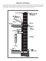
Masonry Chimney
Ensure that a masonry chimney meets the minimum standards of the National Fire Protection Association (NFPA)
by having it inspected by a professional. Make sure there are no cracks, loose mortar or other signs of deterioration
and blockage. Have the chimney cleaned before the stove is installed and operated. When connecting the
stove through a combustible wall to a masonry chimney, special methods are needed.

-12-
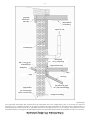
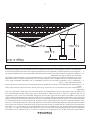
Method A. 12” (304.8 mm) Clearance to Combustible Wall
Member: Using a minimum thickness 3.5” (89 mm) brick
and a 5/8” (15.9 mm) minimum wall thickness clay liner,
construct a wall pass-through. The clay liner must conform
to ASTM C315 (Standard Specication for Clay Fire Linings)
or its equivalent. Keep a minimum of 12” (304.8 mm) of brick
masonry between the clay liner and wall combustibles.
The clay liner shall run from the brick masonry outer surface
to the inner surface of the chimney ue liner but not past
the inner surface. Firmly grout or cement the clay liner in
place to the chimney ue liner.
Method B. 9” (228.6 mm) Clearance to Combustible Wall
Member: Using a 6” (152.4 mm) inside diameter, listed,
factory-built Solid-Pak chimney section with insulation of 1”
(25.4 mm) or more, build a wall pass-through with a minimum
9” (228.6 mm) air space between the outer wall of the
chimney length and wall combustibles. Use sheet metal
supports fastened securely to wall surfaces on all sides,
to maintain the 9” (228.6 mm) air space. When fastening
supports to chimney length, do not penetrate the chimney
liner (the inside wall of the Solid-Pak chimney). The inner
end of the Solid-Pak chimney section shall be ush with the
inside of the masonry chimney ue, and sealed with a non-
water soluble refractory cement. Use this cement to also
seal to the brick masonry penetration.
Method C. 6” (152.4 mm) Clearance to Combustible Wall
Member: Starting with a minimum 24 gage (.024” [.61 mm])
6” (152.4 mm) metal chimney connector, and a minimum
24 gage ventilated wall thimble which has two air channels
of 1” (25.4 mm) each, construct a wall pass-through.
There shall be a minimum 6” (152.4) mm separation area
containing berglass insulation, from the outer surface of
the wall thimble to wall combustibles. Support the wall
thimble, and cover its opening with a 24-gage minimum
sheet metal support. Maintain the 6” (152.4 mm) space.
There should also be a support sized to t and hold the
metal chimney connector. See that the supports are
fastened securely to wall surfaces on all sides. Make sure
fasteners used to secure the metal chimney connector do
not penetrate chimney ue liner.
Method D. 2” (50.8 mm) Clearance to Combustible Wall
Member: Start with a solid-pak listed factory built chimney
section at least 12” (304 mm) long, with insulation of 1” (25.4
mm) or more, and an inside diameter of 8” (2 inches [51
mm] larger than the 6” [152.4 mm] chimney connector).
Use this as a pass-through for a minimum 24-gauge single
wall steel chimney connector. Keep solid-pak section
concentric with and spaced 1” (25.4 mm) off the chimney
connector by way of sheet metal support plates at both
ends of chimney section. Cover opening and support
chimney section on both sides with 24 gage minimum
sheet metal supports. See that the supports are fastened
securely to wall surfaces on all sides. Make sure fasteners
used do not penetrate chimney ue liner.
NOTES:
1. Connectors to a masonry chimney, excepting method B, shall extend in one continuous section through the
wall pass-through system and the chimney wall, to but not past the inner ue liner face.
COMBUSTIBLE WALL CHIMNEY CONNECTOR PASS-THROUGHS

-13-
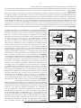
MACHINE SCREW
CABINET DOOR KNOB
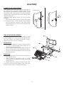
Assembly
CABINET DOOR KNOB ASSEMBLY
The cabinet door knob is mounted on the inside of
the cabinet door to facilitate shipping and must be
removed and re-installed for proper usage. To get
the cabinet door open, place your hand under the
cabinet frame (right hand side of the cabinet door)
and push door out.
FOLLOW THESE INSTRUCTIONS FOR DOOR KNOB
ASSEMBLY:
1. Remove the machine screw and the door knob.
2. Place the knob on the outside of the cabinet
door, re-install the machine screw and tighten
being careful not to strip out the threads in the
plastic handle.
CB36 ROOM BLOWER ASSEMBLY
NOTICE: The CB36 is standard equipment on the
model VG900B. If you wish to purchase an assembly,
you can contact your dealer for details or get it
directly from the U.S. Stove Company.
INSTALLATION
3. Remove the Panel (A) using tin snips or knock
out using a hammer and chisel careful not to
distort the mounting surface.
4. Attach the Blower Mounting Box (B) to the rear of
the unit using four(4) of the supplied #10 screws.
5. Then mount the Blower Assembly with the four(4)
remaining screws.
OPERATION
1. Rotating the rheostat control knob clockwise will
turn ON the blower.
2. When turned on, the blower comes on HIGH,
then as the knob is rotated clockwise, the blower
speed reduces.
3. Rotate the knob counter-clockwise to turn OFF.
Caution! Route the Power Supply Cord away from
the heat source and out of high trafc areas.

-14-
A
B
C
D
NOTE: During opening and closing of the feed and ash doors of this heater, it may seem that the t of the
door is "too tight". As the heater is red, the gasketing "settles" or "seats" itself in the door. The tight t at the
factory and before the heater's initial ring is to insure a good seal after the gasketing "settles".
INSTRUCTIONS FOR TWO-STEP LATCH OPERATION
Follow these instructions to operate you unit safely when operating the feed door.
1. Turn handle clockwise to the 12 o’clock position (A), pull the door open until you engage the second step
(B).
2. Hold the door in that position for approximately 10 seconds.
3. Then to open door, turn the handle counter clockwise to the 9 o’clock position (C) and then continue to pull
the door open. (D)
4. To close and latch the door, reverse steps 1 through 4.
Note: This new latching mechanism meets codes and provides more safety for the user of this stove.
HOW TO OPEN THE TOP LID
CAUTION! DO NOT OPEN OR CLOSE THE TOP WHEN THE HEATER IS HOT!
To open, grasp the top at the front or on each corner and lift all the way up until the support rod stops the
motion. Then gently lower the top allowing the support rod to settles in the cup, holding the top open.
To Close, lift the top until the support rod is out of the cup. Pull the rod forward and lower the lid closed.
Assembly

-15-
FUEL RECOMMENDATIONS
Coal - Most sizes of bituminous coal will work in your heater; for best results we recommend large nut coal to
small egg coal (1-3/4” diameter to 4” diameter). When burning anthracite, use egg or broken with sizes between
2-5/16” and 4-3/8”. Note that it is important to the life of your stove to buy coal which has been sized and
cleaned. Cleaning insures removal of rocks and other materials.
DO NOT burn coke, charcoal, high volatile bituminous coal, sub bituminous, lignite or cannel coal (sometimes
called channel coal or candle coal). STORE COAL IN A DRY, WELL VENTILATED AREA.
LIGHTING
1. Set the thermostat on “HIGH” and open both spin dampers on the feed and ash door for maximum draft.
2. Open the feed door and place paper and wood kindling on the grate for starting the re.
3. Light the kindling and close the door.
4. Once a re is established and burning briskly, add approximately 15 pounds of coal, being careful not to
smother out the kindling re.
For the rst few burns, build small res to allow the cast iron components and painted cabinet parts to season
or cure. Your new stove will emit some smoke and odors from the curing process but should only do so for a short
period of time. We suggest opening a window in the room of which the unit is installed.
ADDING FUEL
When maintaining a re, add small amounts of fuel periodically as required (enough to burn for 3 to 5 hours). As
you become more familiar with the operation of your heater, it is possible to add coal to burn for longer durations
of 8 to 10 hours. But doing so carelessly will promote incomplete combustion and considerable sooting along with
a very dirty, inefcient re.
1. Always set the thermostat to high before opening the feed door to refuel or stoke the re.
2. When opening the feed door, turn handle and open door until it stops on the latch and leave it at that position
for at least 10 seconds before opening fully. This, along with step 1 above, will allow any accumulated gases
or smoke to exit into the chimney, eliminating ame or smoke spillage into the room.
3. If need be, shake the grate vigorously back and forth to dump the ashes into the ash pan. Do this at least
once every 12 hours of operation.
4. Never smother the re when adding fuel.
5. Add fresh kindling if the bed of coals has cooled.
6. Never add fuel above the top of the rebrick.
7. Be sure the new fuel is burning before you close the door and adjust combustion air.
8. Refer to the Bulletine RC454 in this manual for more information on burning coal.
9. Adjust dampers and air shutters to obtain the burn you desire. The air shutter on the thermostat control should
never be closed complete when burning coal.
10. Empty ash pan regularly. Do not allow the ashes to build up to the grate as the grate will warp and burnout
will occur. Allowing ashes to build up may also result in ash spillage when removing the ash pan. Dispose of
hot ashes properly (See Maintenance).
Operating Instructions
Caution!
• Hot while in operation. Keep children, clothing, furniture away. Contact may cause skin burns.
• Never use gasoline, gasoline-type lantern fuel, kerosene, charcoal lighter uid, or similar liquids to start or
“freshen up” a re in this heater. Keep all such liquids well away from the heater while it is in use.
• Do not operate this heater with the feed or ash door open. This heater is designed for thermostatic
operation. Operating with either door open will overheat and damage the heater.
• Always close the doors after the ignition.
• Never overre your stove. If any part of the stove starts to glow red, over ring is happening. Readjust the
air intake control to a lower setting.
• Build res directly on the grate in the heater.
• Do not burn garbage, ammable uid such as gasoline, naphtha or motor oil.
• Do not store fuel or other combustible materials within the minimum clearances specied in this manual or
within the space required for charging and ash removal. Doing so could result in a house re.
• Never alter the adjustment range or air inlets to increase ring for any reason.
CAUTION! Never use the manufactured coal bricks that are made from coal dust and a wax type binder.

-16-
A guide to burning coal in your heater.
Heaters that are capable of burning coal usually will burn both Bituminous and Anthracite coal. Anthracite is
perhaps the best coal fuel because of its long even burn time, high heat output, and cleanliness which make it a
good choice for the home. However, keep in mind it is a much more difcult fuel to use, requires more care and
patience, is not so widely available, and is usually much more expensive than Bituminous
SIZE OF COAL
Most sizes of Bituminous Coal will work in a coal heater; for best results we recommend large “nut” coal to small
“egg” coal (1-3/4” diameter to 4” diameter). When burning Anthracite, use “egg” or “broken” with sizes between
2-5/16” thru 4-3/8”. Note that it is important to the long life of your stove to buy coal which has been sized and
cleaned. Cleaning insures removal of rocks and other minerals. Never use coal smaller than 1” or larger than 5”
in diameter. Small sized coal will smother the re. Too large a size of coal will not burn well.
STOVE OPERATION
All coal res should be started with wood which will allow the re to get hot enough to ignite the coal. The best
ignition res utilize dry pine or other resinous soft woods as kindling, with hard wood (oak, hickory, ash) added to
increase the heat prior to addition of the coal.
Before starting the re, open the stove pipe damper (if equipped), turn the thermostat to high, open the ash
pit door and feed door, place newspaper and nely split kindling on the grate, light the paper, add larger hard
wood after the kindling is burning brightly. Caution: Never use gasoline, lantern fuel, kerosene, charcoal lighter
uid, or other ammable liquids to start or freshen up a re in any heater. Place the larger pieces of wood on the
re so that they are slightly separated and form a level for the addition of coal. It will take 10 to 20 minutes before
this wood is thoroughly ignited. Adding coal too soon will cut the air supply and smother the re.
BURNING BITUMINOUS
Once your kindling and wood re has produced a bed of well established coals, start adding coal in layers
allowing each to ignite before adding more. Bituminous has a high volatile content and, as a result, should be
red with the “conical method” - with the highest portion of your re bed in the center of the rebox. The rst
ames will be long and generally orange or yellow and produce quite a bit of smoke. As the gases burn off the
ames become shorter, change color and produce less smoke.
Once the re is WELL ESTABLISHED add coal to the center of the rebox forming the cone. Burning in this fashion
allows heat to drive off the volatile gases, and turbulence created increases the burn efciency. There will have
to be some experimenting with the individual setup as no two chimney’s or installations are going to be the same.
Just remember to allow enough air to enter the rebox and keep the stove pipe damper open so that volatiles
are properly burned. Before refueling, take the time to break up the cone a little with a poker, especially if it has
caked over or formed a crust. But, be careful not to mix the coal as this increases the chances of forming clinkers.
When shaking the grate(s) be gentle. Just a few short movements - a couple of “cranks” - is better than a lot of
agitation. The objective is to remove a small amount of the ashes without disturbing the re. Stop when you see
a glow in the ashes or the rst red coals fall into the ash pan. Excessive shaking wastes fuel and can expose the
grate(s) to very high temperatures which can cause warping or burnout.
For overnight operation (long duration burn time) shake the re and add coal, retaining the center cone. Once
the volatile are burned off, close the feed door and adjust the stove pipe damper, if equipped. Then adjust the
thermostat to the desired heat level.
More MAINTENANCE will be needed with bituminous coal than with anthracite coal as more soot will collect on
heating surfaces and in pipes, requiring more frequent cleaning.
ANTHRACITE
Add a thin layer of coal (preferably smaller chunks) to the wood re, being careful not to disturb it too much or
cut off the draft. Then, add a second heavier layer after the coal is ignited and burning well. If necessary, add a
third layer to bring the coal up to the top of the front liner (not above!). Be sure to close the ash door.
Before adding further fuel, be sure to leave a red spot of glowing coals in the center of the rebox to insure that
the re has not been smothered and to help ignite the gases given off by the new charge. A deep charge will
give a more even heat and a longer re, but it may take one to two hours before the whole bed is fully ignited.
When the re is well established and the room is becoming warm, partially close the dampers. Some experimenting
will have to take place with each particular setting of all dampers and controls as the chimney provides the draft
necessary to not only exhaust the smoke, but to pull combustion air into the heater as well - and no two chimney’s
perform the same. Under ideal draft conditions, one should be able to turn the secondary air supply on the feed
door to a near closed position - but leave the ash pit damper at least partially open to prevent the re from going
Bulletin RC454

-17-
out. Adjust the stove pipe damper to reduce the draft on the re. With anthracite there will be short blue ames
above the coal, except when the re is started or a new charge is added. If, however, there is no ame then the
re needs more air from the bottom (unless it is near the end of its burn cycle and needs to be recharged).
Only when the coal is burned down to half its original depth it is time to add fresh coal. When doing so, open the
stove pipe damper and turn the thermostat damper to high, which will allow the re to burn off any accumulated
gases. Open the feed door, and with a small rake, hoe, or hooked poker pull the glowing coals to the front of
the rebox. Try not to disturb the re too much. Next, add a fresh charge to the back being careful not to seal off
the top. Close the feed door, but leave the spin damper (or thermostat) open for a few minutes until the volatile
gases have burned off. It is not necessary to shake down the ashes each time you refuel the furnace. Experience
will be your best teacher.
BANKING THE FIRE
For extended operation, such as overnight, the re will need to be banked. To do so heap coal up along the
sides and back of the rebox so that the re gradually burns it over a longer period of time. The intensity of the
re will also be reduced without letting it go out. Follow the same procedure as for refueling. If possible, avoid
shaking, as a heavier layer of ash will help reduce the intensity of the re during this time. After loading, let the re
establish itself for about 30 minutes. Then close your damper and automatic control to the point where the house
does not become too cold. It is important that you begin banking early enough before retiring or leaving that
you can make necessary adjustments after the re is well established.
To revive a coal re that is almost out, (1) open the ash door and stove pipe damper and close the spin damper
under the door to get a good draft through the grate. (2) place a thin layer of dry coal over the entire top of
the re. DO NOT POKE OR SHAKE THE FIRE AT THIS TIME! (3) after the fresh coal has become well ignited shake the
grate (just a little), refuel.
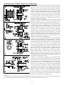
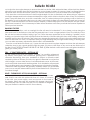
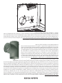
DR6 - 6” DRAFT REGULATOR - OPTIONAL KIT
In the unlikely event that your heater “overres” (a condition evidenced
by elbows, stove pipes, and connectors glowing red in appearance or
otherwise discoloring), then your installation is subject to excessive draft
created by either a chimney too tall or too great in diameter in conjunction
with its height, or some other factor of an indeterminate cause. In this event,
you should install a barometric draft regulator. Such installation will preclude
any over-ring and/or any hazardous consequences of potential overring.
Barometric draft regulators are generally available where you purchased
your stove or may be ordered directly from United States Stove Company at
a nominal charge.
B36TK - THERMODISC KIT FOR B36 BLOWER - OPTIONAL
Wish your blower would turn ON and OFF as the heater gets warm
and cold? It can with this optional kit from U.S. Stove. It connects
in line with your power supply cord and mounts to the back of
the heater. When the snap disc reaches 120 degrees, the blower
automatically turns ON and turns itself OFF if it reaches 90 degrees.
See your Dealer for details or call U.S. Stove directly.
Bulletin RC454

-18-
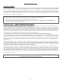
Maintenance
DISPOSAL OF ASHES
Ashes should be removed from the stove every few days or when ashes get to 2 to 3 inches deep. Always empty
the stove when it is cold, such as in the morning. Ashes should be placed in a metal container with a tight tting
lid. The closed container of ashes should be placed on a non combustible oor or on the ground, well away from
all combustible materials, pending nal disposal. If the ashes are disposed of by burial in soil or otherwise locally
dispersed, they should be retained in the close container until all cinders have thoroughly cooled. Do not use the
ash container to dispose of other trash.
CREOSOTE / SOOT - FORMATION AND NEED FOR REMOVAL
When coal is burned slowly, it produces tar and other organic vapors, which combine with expelled moisture
to form creosote or soot. The creosote vapors condense in the relatively cool chimney ue of a slow-burning
re. As a result, creosote/soot residue accumulates on the ue lining. When ignited this creosote/soot makes an
extremely hot re. When burning coal, the chimney connector and chimney should be inspected at least twice
a month during the heating season to determine if a creosote/soot build-up has occurred. If creosote/soot has
accumulated, it should be removed to reduce the risk of a chimney re.
If a chimney or creosote re occurs, close all dampers immediately and call the re department.
Once a chimney re occurs, it can only be extinguished by removing its source of oxygen. This can be
accomplished by shutting any mechanical draft devices and/or discharging a CO² (Carbon Dioxide) or Halon
re extinguisher directly into the heater through an appropriately placed cleanout. If using a Halon extinguisher,
please note that it totally displaces oxygen and could become a hazard in itself if enough is discharged into the
living space.
Wait for the heater to cool, then inspect the chimney area for damage. A chimney re may cause ignition of
wall studs or rafters which you thought were at a safe distance from the chimney. If no damage results, perform
a chimney cleaning to ensure there is no more creosote deposits remaining in the chimney. We suggest having
your chimney inspected by a qualied person before using again.
Establish a routine technique for seasoning, storing, and burning your fuel. Check daily for creosote build-up until
experience shows how often you need to clean to be safe. Be aware that the hotter the re, the less creosote or
soot is deposited and weekly cleaning may be necessary in mild weather even though monthly cleaning may
be enough during the colder months. Contact your local municipal or provincial re authority for information on
how to handle a chimney re if one occurs. Have a clearly understood plan to handle the situation if such an
event were to happen.
NOTICE: Keep your chimney connector and chimney clean and in good condition. Doing so can maintain
heater efciency and reduce the risk of a re.
CAUTION:
• Ashes could contain hot embers even after two days without operating the stove.
• The ash pan can become very hot. Wear gloves to prevent injury.
• Never burn the stove with the ash door open. This would result in over ring the stove. Damage to the
stove and even a house re may result.

-19-
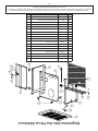
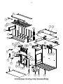
Internal Parts Diagram
654
24
25
7 8
30
29
27
26
31
32
33
34
30
35
36
34
30
31
20
21
22
23
18
19
13
15
16
17
14
13
3
2
1
11
912
10
38
28
37

-20-
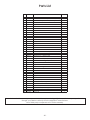
In order to maintain warranty, components must be replaced using original manufacturers parts purchased
through your dealer or directly from the appliance manufacturer.
Use of third party components will void the warranty.
Key Part No. Description Qty.
1 67859 Weldment, Base 1
2 22030 Shield, Second Heat (Included w/ 67859) 1
3 22110 Shield, Heat (Included w/ 67859) 1
4 68619 Assy., Heat Jacket 1
5 88032 Gasket, Flue Collar 1
6 40246 Collar, Flue 1
7 22090 Curtain, Smoke 1
8 22171 Clip, Smoke Curtain 2
9 40075 Frame, Draft Damper 1
10 67132 Damper, Draft Control 1
11 25550 Pin, Draft Damper 1
12 83890 Clip, Push 1
13 40100 Liner, Front/Back 3
14 22536 Support, Grate 2
15 40102 Grate, Frame 1
16 40101 Grate, Coal 1
17 40045 Shaker 1
18 40132 Retainer, Brick 2
19 89066 Firebrick (4.5” x 9” x 1.25”) 10
20 891940 Assy., Feed Door (Complete) 1
- 40199 Feed Door - Casting Only -
21 88033 Rope Gasket, 3/8” 3.75 ft.
22 891941 Assy., Ash Door (Complete) 1
- 40289 Ash Door - Casting Only -
23 88033 Rope Gasket, 3/8” 2.42 ft.
24 83872 Pin, Door - Short 1
25 23441 Pin, Door - Long 1
26 83102 Bolt, 1/4-20 x 1.25” CS, Slotted Hd. 2
27 40056 Wheel, Draft 2
28 83415 Nut, 1/4-20 Jam 2
29 25201 Shield, Flame 2
30 83250 Kep Nut, 1/4-20 4
31 40509 Handle, Door 2
32 89523 Handle, Drop Wood 1
33 22434 Latch, Door (2-Step) 1
34 83045 Washer, Flat 2
35 83273 Washer, Spacer 1
36 22108 Latch, Door (Door Stop) 1
37 23474 Liner, Top 1
38 67444 Ash Pan 1
Parts List
Page is loading ...
Page is loading ...
Page is loading ...
Page is loading ...
Page is loading ...
Page is loading ...
Page is loading ...
Page is loading ...
Page is loading ...
Page is loading ...
Page is loading ...
Page is loading ...
Page is loading ...
Page is loading ...
Page is loading ...
Page is loading ...
Page is loading ...
Page is loading ...
Page is loading ...
Page is loading ...
Page is loading ...
Page is loading ...
Page is loading ...
Page is loading ...
Page is loading ...
Page is loading ...
Page is loading ...
Page is loading ...
-
 1
1
-
 2
2
-
 3
3
-
 4
4
-
 5
5
-
 6
6
-
 7
7
-
 8
8
-
 9
9
-
 10
10
-
 11
11
-
 12
12
-
 13
13
-
 14
14
-
 15
15
-
 16
16
-
 17
17
-
 18
18
-
 19
19
-
 20
20
-
 21
21
-
 22
22
-
 23
23
-
 24
24
-
 25
25
-
 26
26
-
 27
27
-
 28
28
-
 29
29
-
 30
30
-
 31
31
-
 32
32
-
 33
33
-
 34
34
-
 35
35
-
 36
36
-
 37
37
-
 38
38
-
 39
39
-
 40
40
-
 41
41
-
 42
42
-
 43
43
-
 44
44
-
 45
45
-
 46
46
-
 47
47
-
 48
48


United States Stove VG900 Owner's manual
- Category
- Fireplaces
- Type
- Owner's manual
Ask a question and I''ll find the answer in the document
Finding information in a document is now easier with AI
in other languages
Related papers
-
United States Stove TR009 Owner's manual
-
United States Stove TR008 Owner's manual
-
-
-
United States Stove Forester 3500 User manual
-
United States Stove B2350 Installation guide
-
-
-
-
Other documents
-
 Vogelzang International BX42E User manual
-
 Vogelzang International BX26E Owner's manual
-
USSC AWC31 User guide
-
Vogelzang TR007 User guide
-
Vogelzang International VG650ELG Owner's manual
-
-
Hearth and Home Technologies 8040 04-28-04 User manual
-
Jotul F 100 USA User manual
-
-
SCAN A10 Instructions For Installation And Use Manual

