UEi Phoenix Series User manual
- Category
- Measuring, testing & control
- Type
- User manual

1-800-547-5740 • Fax: (503) 643-6322
w

• If any of the following indications occur during testing, turn
off the power source to the circuit under test:
• Arcing
• Flame
• Smoke
• Extreme Heat
• Smell of Burning Materials
• Discoloration or Melting of Components
WARNING!
H i gher voltages and currents re q u i r e greater awareness of physical safety
h a z a r ds. Before connecting the test leads; turn off the power to the circ u i t
under test; set the meter to the desired function and ra n g e; connect the test
leads to the meter first, then connect to the circuit under test. Reapply
p o w e r. If an erroneous reading is observed, disconnect power immediately
and recheck all settings and connections.
This meter is designed for trade professionals who are familiar with the
hazards of their trade. observe all recommended safety procedures that
include proper lock-out utilization and the user of personal protective
equipment that include safety glasses, gloves and flame resistant clothing.
International Symbols
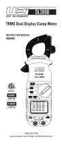
Controls and Indicators
1. Clamp: Measures inductive AC current. Opens to 1. 2 5” (32 mm).
2. W i re Separation Ta b : Used to separate bundled wires to
aid in measuring.
Introduction
The Phoenix Series is a hand-held, battery powered digital multimeter
with clamp-on current measuring capability, back light and work
area light.
Features include
• 3-3/4 digit, 4000 count LCD display
• Auto-ranging measurement with manual ranging (Amps or
adapters only) capability
• MIN/MAX (Peak Hold) (all ranges except Frequency)
• Frequency/Duty Cycle/Data Hold
• Auto power off with manual override
• Detachable current probe with optional current hook adapter
for tight spaces
• Built-in test lead storage & magnetic mount
• Backlit display & Worklight
DL279 & DL289
• Temperature/Non-Contact Voltage/Dual display
• TRMS Measurement (DL289 only)
Safety Notes
Before using this meter, read all safety information carefully. In this
manual the word "WARNING" is used to indicate conditions or actions
that may pose physical hazards to the user. The word "CAUTION" is
used to indicate conditions or actions that may damage this instrument.
• Do not attempt to measure any voltage that exceeds the category
based rating of this meter
• Do not attempt to use this meter if either the meter or the test
leads have been damaged - Turn instrument in for repair at a
qualified repair facility
• Ensure meter leads are fully seated by making a quick continuity
check of the leads prior to making voltage measurements
• Keep your fingers away from the test lead’s metal probe contacts
when making measurements - Always grip the leads behind the
finger guards molded into the probes
• Do not open the meter to replace batteries or while the probes
are connected
WARNING!
Exceeding the specified limits of this meter is dangerous and can
expose the user to serious or possibly fatal injury.
• Voltages above 60 volts DC or 25 volts AC may constitute a serious
shock hazard
• Always turn off power to a circuit (or assembly) under test before
cutting, unsoldering, or breaking the current path - Even small
amounts of current can be dangerous
• Always disconnect the live test lead before disconnecting the
common test lead from a circuit
• In the event of electrical shock, ALWAYS bring the victim to the
emergency room for evaluation, regardless of the victim’s apparent
recovery - Electrical shock can cause an unstable heart rhythm that
may need medical attention
DL269/DL279/DL289-MAN P. 1
1
3
6
7
11
12
15
16
17
10
13
14
18
2
4
5
8
9

18. Multifunction Input Port: Used for measuring AC/DC Volts,
Frequency or Duty Cycle, Resistance, Diode, Continuity
and Capacitance.
Displays and Indicators
~
AC indica t o r
= DC indica t o r
- I n d i c ates a negative value (DC Negative Vo l t a g e )
M a x M a ximum value displayed
M i n Minimum value displayed
A (top display) Display is in Amps from UEi Clamp or Hook adapter
A D P (top display) M a ximum value displayed
Low battery symbol
Hold function activated
Diode function
C o n t i n u i t y function
nF / µF Capacitance (nanofarads or microfara d s )
µ A Microamps (1 µA is 0.000001 Amp)
H z Fr e q u e n cy measurement
% D u t y Cycle measurement
m V Millivolts (1 mV is 0.001 Vo l t )
A P O Auto power off mode active
AT Auto range function active
O . L Displayed if the input value exceeds selected ra n g e
Operating Instructions
Auto power off
After powering off, the meter will turn back on if you perform one of
the following; Change the range, move the position of the selector or
any other button is pressed.
To disable this function; press and hold the "SELECT" button while
turning the meter on. The “APO” indicator will now be off, indicating
that the auto power off function is not active.
Back-light / work area light
Press the “HOLD” button longer than two seconds to activate the
backlight/work area light. The lights automatically turn off after
10 seconds to extend battery life.
NOTE: After activating worklight, press briefly to activate hold.
Auto / Manual Range
In auto range the meter will select the best range for the measured value,
and "AT" is displayed in the lower left of the display. Press the "RA N GE"
button to cycle through available ranges for the upper display. “AT” will
not be on the display when locked in a specific ra n g e .
3. Conductor Alignment Marks: Used to aid in the visual alignment of
a conductor when measuring inductive amperage. Greatest accura cy
is achieved when the conductor inside the clamp is centered at the
intersection of these marks.
4. Test Lead Holder: Used for hands-free use of one of the test probes.
5. Hand Guard : Used as a point of reference for the operators safety.
WARNING!
Always keep your hands and fingers behind the hand guards
when measuring current on exposed conductors. Contact may
result in serious injury.
6. Clamp Le v e r : Opens and closes current clamp jaw.
NOTE: The clamp uses a high tension spring to close the jaw.
Do not allow fingers or objects to become pinched in the base
as jaw closes.
7. MIN/M AX Button: Activates MIN / M A X capture function, cycles
through minimum value, maximum value. Press longer than two
seconds to return to current reading.
8. NCV/Range Button: Activates non-contact voltage function
when meter is off. Used to select “R a n g e“ for the upper display
when meter is on. (NCV only available on DL279 / D L 28 9 )
9. Upper Display (DL279/DL289 only): Used to display current
when used with UEi clamp or hook adapter. Displays output from
other accessories when connected to the UEi meter.
10. Lower Display: Used to display input to test lead jacks. Includes
AC/DC Volts, Frequency, Resistance, Diode, Capacitance and
AC/DC microamps (µA).
11. Select Button: Used to choose measurement mode from
selections with multiple options such as AC or DC volts, AC or DC
µA, Resistance, Diode, Capacitance or Continuity, Temperature
in ˚F or ˚C.
NOTE: Press and hold when turning the meter on to disable
auto power off.
12. Hz/Duty Button: Used to scroll through Frequency or Duty
Cycle when in the AC Voltage measurement mode.
13. HOLD/Backlight Button: Freezes display or activates display
backlight and work area light.
14. Temperature Input Jack: Input jack for k-type thermocouple
probe (DL279/DL289 only).
15. Power/Function Selector: Turns meter on and is used to
select the range or function.
16. Common Te r m i n a l : The black test lead is plugged into this terminal
to supply the ground or “low” reference for all measurements.
17. Category Max Indicator: Indicates maximum voltage for the
rated working category.
WARNING!
Do not exceed 1000 volts DC or AC - RMS at either the common
or multifunction input ports as measured from earth ground.
DL269/DL279/DL289-MAN P. 2
DL279/DL289
DL269

MIN/MAX mode
When using the MIN / M A X capture mode for Amps, it is recommended
that you first select the range of the expected maximum value. If this
is not done it will lock in the lowest range possible for the initial
measurement. If the maximum value exceeds this range the meter will
capture “O . L” as the maximum value.
Manual ranging will also provide a faster response current input.
Data Hold
Press the “ “ button to activate. This will freeze the reading and
range in the display for your review.
Measuring AC Amps
Measuring AC or DC Volts
Measuring Frequency or Duty Cycle
Measuring Resistance, Continuity, Diode and Capacitance
NOTE: Capacitance - leave the meter connected to the capacitor for
10 seconds or more for the reading to stabilize.
Diode - “OL” in reverse mode and approximate forward voltage
drop when connected in forward mode.
Continuity - sounds the tone at approximately 50Ω or less.
Measuring AC, DC or µA
Measuring Temperature ( D L 2 79 / D L 289 only)
Measuring NCV
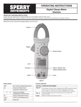
Optional Extended Clamp Head (CH2)
(Sold separately)
NOTE: Remove the hook adapter when not in use to extend battery life. The
hook will consume a small amount of battery power when connected to the
meter even when the meter display is off. The meter will automatically
display “A” for amps with the CH2 or “ADP” for other adapters.
DL269/DL279/DL289-MAN P. 3
Press “SELECT” to change the
reading from AC to DC.
• DL269
Select “ADP” to measure AC
Amps with the clamp head or
hook
• DL279/DL289
Select any range to power the
upper display
Press “Min/Max” to activate Max
capture, Min capture, or normal
display.
Press “NCV/RANGE” to select
range prior to MIN/MAX.
Meter must be in AC Volts mode first
then press “Hz/Duty” to change
function to Frequency or Duty Cycle.
NOTE: Frequency greater than
100Khz will display “0.000 Hz”
Press “SELECT” to move from
Resistance mode to Continuity, diode
or continuity mode.
NOTE: Meter must be in series for µA
measurements. Press “SELECT” to
change AC or DC source.
WARNING!
Do not exceed 2000µA AC or DC
current or damage to the meter
may occur.
Press “SELECT” to change scale from
˚F to ˚C.
WARNING!
Disconnect test leads from any
voltage source and the meter before
plugging in thermocouple.
Non-Contact Voltage
(DL279/DL289 only)
Non-contact voltage with the power
switch in the off position, press and
hold the “NCV” button and move the
meter near this voltage source.
Optional
CH2 hook
Connection
for optional
CH2 hook

M a i n t e n a n c e
Periodic Service
WARNING!
Repair and service of this instrument is to be performed by qualified
personnel only. Improper repair or service could result in physical
degradation of the meter. This could alter the protection from electrical
shock and personal injury this meter provides to the operator. Perform
only those maintenance tasks that you are qualified to do.
Cleaning
Pe r i o d i cal ly clean your meter’s case using a damp cloth. DO NOT u s e
a b ras ive, flammable liquids, cleaning solvents, or strong detergents as
they may damage the finish, impair safety, or affect the reliability of the
s t r u c t u ral components.
Battery Replacement
Remove screws from battery compartment cover on back of meter and
remove cover. Replace batteries with fresh batteries paying attention to
p o l a r i ty position. Replace cover and screw s .
Specifications
AC Amps Measurement - Jaw input (45Hz to 400Hz)
*DL269 400A range only
*DL289 45Hz to 400Hz True RMS (Crest factor <3:1)
DC Low Amps Measurement (test lead input)
AC Low Amps Measurement (test lead input, 45Hz to 400Hz)
*DL289 45Hz to 400Hz True RMS (Crest factor <3:1)
DC Volts Measurement
AC Volts Measurement (45Hz to 400Hz)
*DL289 45Hz to 1KHz True RMS (Crest factor <3:1)
Ohms Measurement
Diode Test
Capacitance Measurement
Temperature Measurement (DL279 & DL289 only)
Frequency Measurement
Minimum frequency: 0.5Hz, DC V offset should be zero
Sensitivity: > 1.0V rms
Duty (%) Cycle Measurement
0.5Hz to 100kHz (pulsewidth > 2µ sec)
Continuity Measurement
Physical Specifications
DL269/DL279/DL289-MAN P. 4
Range Resolution Accuracy Overload Protection
40A 0.01A ±2.9% +15 dgts 600V
400A 0.1A ±1.9% +8 dgts
Range Resolution Accuracy Overload Protection
400µA 0.01µA ±1.2% +3 dgts 2000µA / 600V
2000µA 0.1µA
Range Resolution Accuracy Overload Protection
400µA 0.01µA ±2.0% +5 dgts 2000µA / 600V
2000µA 0.1µA ±1.5% +5 dgts
Range Resolution Accuracy Overload Protection
400mV 0.1mV ±0.5% +4 dgts 600V
4V 1mV
40V 10mV
400V 100mV
1000V 1V ±0.8% +10 dgts
Range Resolution Accuracy Overload Protection
4V 1mV ±2.0% +5 dgts 600V
40V 10mV
400V 100mV
750V 1V
Range Resolution Accuracy Overload Protection
400Ω 100mΩ ±1.0% +4 dgts 600V
4kΩ 1Ω
40kΩ 10Ω
400kΩ 100Ω
4MΩ 1kΩ
40MΩ 10kΩ ±2.0% +4 dgts
Range Open Circuit Vo l t a g e Test Current (typical) Overload Protection
2.0V < 3.0V DC 0.25mA 600V
Range Resolution Accuracy Overload Protection
40nF 0.01nF ±3.5% +6 dgts 600V
400nF 0.1nF
4µF 0.001µF
40µF 0.01µF
400µF 0.1µF
4000µF 1µF
Range Resolution Accuracy Overload Protection
-22˚ to 14˚F 0.1˚F ±5.4˚F 30V
(-30˚ to -10˚C) (0.1˚C) (±3.0˚C)
15˚ to 752˚F 0.1˚F ±1.0% +3.6˚F
(-9˚ to 400˚C) (0.1˚C) (±1.0% +2.0˚C)
Range Resolution Accuracy Overload Protection
9.999Hz 0.001Hz ±0.1% +4 dgts 600V
99.99Hz 0.01Hz
999.9Hz 0.1Hz
9.999kHz 1Hz
99.99kHz 10Hz
Range Accuracy Overload Protection
01. to 99.9% ±(0.2% per kHz +0.1%) +5 count 600V
Open Circuit voltage <2.7V Overload Protection
Threshold Approximately <20Ω 600V
Operation temperature 32˚ to 104˚F (0˚ to 40˚C)
Storage temperature -4˚ to 140˚F (-20˚ to 60˚C)
Relative humidity 0% to 80% at 32˚ to 95˚F (0˚ to 35˚C),
0% to 70% at 32˚ to 131˚F (0˚ to 55˚C)
Temperature coefficient Nominal 0.1 x (Specified accuracy) / ˚C
(<18˚ or >28˚C ; <64˚ or >82˚F)
Altitude Operating - up to 2000m
Storage - 10000m
Pollution degree 2
Installatin category CAT III 600V, CAT II 1000V
Certifications UL & cUL standard UL 3111-1 Listed

-
 1
1
-
 2
2
-
 3
3
-
 4
4
-
 5
5
-
 6
6


UEi Phoenix Series User manual
- Category
- Measuring, testing & control
- Type
- User manual
Ask a question and I''ll find the answer in the document
Finding information in a document is now easier with AI
Related papers


Other documents
-
Omega HHM380 Owner's manual
-
 Sperry instruments DSA1020TRMS Owner's manual
-
Mastech MS2025A User manual
-
GB GDT-311 Operating instructions
-
HTC INSTRUMENT CM-2070C User manual
-
 Sperry instruments DSA540A Owner's manual
-
UEi Test Instruments DL39 User manual
-
 Sperry instruments DSA660 Owner's manual
-
-
CPS AC750 Operating instructions


