StarTech com 4PCIE-PCIE-ENCLOSURE User guide
- Category
- Interface cards/adapters
- Type
- User guide

Quick-Start Guide
To view manuals, FAQs, videos, drivers, downloads, technical drawings, and more, visit www.startech.com/support.
Manual Revision: August 29, 2022
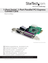
Product Diagram (4PCIE-PCIE-ENCLOSURE)
Expansion Chassis
PCIe 2.0 to 4 PCIe Slots Expansion Chassis - USB Type-C
Port/LED/
Connector Function
1PCIe Expansion
Slots
• Install up to Four PCIe cards
• PCIe version 2.0 x1 slots
• 5 Gbps downstream
• Full length cards supported
2Mounting
Brackets
• (Optional) Allows for a permanent installation of the
Expansion Chassis to a at and stable surface
• Mounting Holes at the Front and Back of the
Expansion Chassis secure the Mounting Brackets
3On/O Switch
• Turns the Expansion Chassis On or O
• The correct sequence to power the device:
• Power on: Power On the Expansion Chassis rst,
then the Host Computer
• Power o: Power O the Host Computer rst, then
the Expansion Chassis
4DC Power Port
• Connect the Expansion Chassis to a Power Source
using the included Power Adapter
• Recommended 12 V and 3 A. Supports 12 to 24 V input
5USB Type-C
Connector
• Used to connect the Expansion Chassis to a Host
Computer
• If the USB Type-C Cable is disconnected during use,
the Host Computer must be restarted to reestablish the
connection
• For a secure and correct cable connection, threaded
holes around the USB Type-C Connector allow to Screw-
lock the included USB Type-C Cable
6USB Type-C LED
Indicator
• Indicates if the included USB Type-C-Cable is on the
correct orientation. The cable is not reversible
• Solid Green = Correct orientation
7Power LED
Indicator
• Indicates if the On/O Switch is turned On or O
• Solid Red = On
• O = O
8Terminal Block
Connector
• Connect the Expansion Chassis to a DC Power Source
• Recommended 12 V and 3 A. Supports 12 to 24 V input
9Metal Cover • Remove the Metal Cover to install the PCIe cards
3
7
4
1
6
5
8
9
2
*Product may vary from image
2

Quick-Start Guide
To view manuals, FAQs, videos, drivers, downloads, technical drawings, and more, visit www.startech.com/support.
Manual Revision: August 29, 2022
PCIE Host Adapter Card
Port/LED/
Connector Function
1Bracket • Secures the card to the Computer Case. The Full height
Bracket comes pre-installed
2USB Type-C
Connector
• Used to connect the PCIE Host Card to the Expansion
Chassis
• For a secure and correct cable connection, threaded
holes around the USB Type-C Connector allow to Screw-
lock the included USB Type-C Cable
3LP4 Power
Connector • Optional: connect the Host Computer Power Supply
4SATA Power
Connector • Optional: connect the Host Computer Power Supply
5PCIe x2
Connector • Insert into a PCI Express Slot
Package Contents
• PCIe to PCIe Expansion Chassis x 1
• PCIe Host Adapter Card
• 6ft (1.8m) USB Type-C to C Male to Male Cable x 1
• Low-Prole Bracket x 1
• Power Adapter x 1
• Terminal Block Connector x 1
• Mounting Brackets x 2
• Mounting Brackets Screws x 4
• Quick-Start Guide x 1
Requirements
For the latest requirements, please visit www.startech.com/4PCIE-PCIE-ENCLOSURE
• Computer with an available PCI Express slot (x2, x4, x8, or x16)
• Phillips head screwdriver
Installation
WARNING!
Static electricity can severely damage the PCIe card(s) ensure that you are adequately
grounded before you open your computer case or touch the PCIe card(s). You should
wear an anti-static strap or use an anti-static mat when installing any computer
component. If an anti-static strap isn’t available, discharge any built-up static
electricity by touching a large grounded metal surface for several seconds. Only handle
the PCIe card(s) by the edges and don’t touch the golden connectors.
Install the PCIe Host Adapter Card
1. Turn O the Computer and any Peripheral Devices that are connected to it (for
example, Printers, External Hard Drives, etc.).
2. Unplug the Power Cable from the back of the Computer.
3. Disconnect any Peripheral Devices that are connected to the Computer.
4. Remove the Cover from the Computer Case. Consult the documentation that came
with the Computer for details about doing this safely.
5. Locate an available PCI Express Slot and remove the corresponding Slot Cover
Plate from the back of the Computer Case. Consult the documentation that came
with the Computer for details about doing this safely. The PCIe Host Adapter Card
works in PCI Express x2, x4, x8, or x16 Slots.
6. Gently insert the PCIe Host Adapter Card into the PCI Express Slot and fasten the
Bracket to the back of the Computer Case.
Note: If you install the PCIe Host Adapter Card into a small form factor or a low-prole
desktop system, it may be necessary to replace the pre-installed standard full-height
bracket with the included low-prole bracket.
8. (Optional) Connect a SATA Power Cable or LP4 from the Host Computer Power
Supply.
9. Return the Cover onto the Computer Case.
10. Reconnect the Power Cable to the back of the Computer.
11. Reconnect all of the Peripheral Devices disconnected in Step 1.
12. Turn On the Computer and Peripheral Devices.
1
3
2
4
5

Regulatory Compliance
FCC - Part 15
This equipment has been tested and found to comply with the limits for a Class B digital device, pursuant to part 15 of
the FCC Rules. These limits are designed to provide reasonable protection against harmful interference in a residential
installation. This equipment generates, uses and can radiate radio frequency energy and, if not installed and used
in accordance with the instructions, may cause harmful interference to radio communications. However, there is no
guarantee that interference will not occur in a particular installation. If this equipment does cause harmful interference to
radio or television reception, which can be determined by turning the equipment o and on, the user is encouraged to try
to correct the interference by one or more of the following measures:
• Connect the equipment into an outlet on a circuit dierent from that to which the receiver is connected.
• Consult the dealer or an experienced radio/TV technician for help
This device complies with part 15 of the FCC Rules. Operation is subject to the following two conditions:
(1) This device may not cause harmful interference, and (2) this device must accept any interference received, including
interference that may cause undesired operation. Changes or modications not expressly approved by StarTech.com
could void the user’s authority to operate the equipment.
Industry Canada Statement
This Class B digital apparatus complies with Canadian ICES-003.
Cet appareil numérique de la classe [B] est conforme à la norme NMB-003 du Canada.
CAN ICES-3 (B)/NMB-3(B)
This device complies with Industry Canada licence-exempt RSS standard(s). Operation is subject to the following two
conditions:
(1) This device may not cause interference, and (2) This device must accept any interference, including interference that
may cause undesired operation of the device.
Le présent appareil est conforme aux CNR d’Industrie Canada applicables aux appareils radio exempts de licence.
L’exploitation est autorisée aux deux conditions suivantes:
(1) l’appareil ne doit pas produire de brouillage, et (2) l’utilisateur de l’appareil doit accepter tout brouillage
radioélectrique subi, même si le brouillage est susceptible d’en compromettre le fonctionnement.
Warranty Information
This product is backed by a two-year warranty.
For further information on product warranty terms and conditions, please refer to www.startech.com/warranty.
Limitation of Liability
In no event shall the liability of StarTech.com Ltd. and StarTech.com USA LLP (or their ocers, directors, employees or
agents) for any damages (whether direct or indirect, special, punitive, incidental, consequential, or otherwise), loss of prots,
loss of business, or any pecuniary loss, arising out of or related to the use of the product exceed the actual price paid for the
product. Some states do not allow the exclusion or limitation of incidental or consequential damages. If such laws apply,
the limitations or exclusions contained in this statement may not apply to you.
Safety Measures
• Read the entire manual and ensure the instructions are fully understood before assembling and/or using this product.
Mesures de sécurité
• Lisez tout le manuel et assurez-vous que vous comprenez les instructions avant de commencer à assembler et utiliser
ce produit.
安全対策
• 最初に取扱説明書を最後まで読み、本製品の組み立て方をすべて理解してから組み立て作業を始めて下さい。
Misure di sicurezza
• Leggere l’intero manuale e assicurarsi di aver compreso tutte le istruzioni prima di iniziare ad assemblare e a utilizzare
questo prodotto.
Säkerhetsåtgärder
• Läs hela manualen och se till att du förstår instruktionerna innan du börjar montera och använda produkten.
FR: startech.com/fr
DE: startech.com/de
ES: startech.com/es
NL: startech.com/nl
IT: startech.com/it
JP: startech.com/jp
StarTech.com Ltd.
45 Artisans Crescent
London, Ontario
N5V 5E9
Canada
StarTech.com Ltd.
Unit B, Pinnacle 15
Gowerton Road
Brackmills,
Northampton
NN4 7BW
United Kingdom
StarTech.com LLP
4490 South Hamilton
Road
Groveport, Ohio
43125
U.S.A.
StarTech.com Ltd.
Siriusdreef 17-27
2132 WT Hoofddorp
The Netherlands
Install PCI Express Cards in the Expansion Chassis
Sharp edges! Be mindful of the sharp edges around the Expansion Chassis when the
Metal Cover is removed.
1. Turn O the Expansion Chassis and unplug all cable connections.
2. Turn O the Host Computer.
3. Release the Metal Cover by removing the Screws (x 12) using a Phillips Head
Screwdriver. There are Screws on top and the side opposite to the connectors on the
Expansion Chassis.
4. Locate an available PCI Express Slot on the Expansion Chassis, using a Phillips
Head Screwdriver remove the corresponding Slot Cover Plate from the Expansion
Chassis.
5. Gently insert the PCI Express Card (s) into the PCI Express Slot and fasten the
Bracket to the Expansion Chassis. The Expansion Chassis supports PCI Express
Cards x1 only.
6. Install the Metal Cover back onto the Expansion Chassis.
7. Screw-Lock the USB Type-C Cable onto the Expansion Chassis and the PCIe Host
Adapter Card on the Host Computer. This ensures the correct cable orientation.
8. Connect the Power Adapter or use the optional Terminal Block Connector to supply
power. Turn On the Expansion Chassis by ipping the On/O Switch.
9. Turn On the Host Computer.
No drivers are needed for the Expansion Chassis. Some PCI Express Cards may need
drivers to nish their installation.
(Optional) Install the Mounting Brackets
1. Use the Mounting Screws (x 2) and Phillips Head Screwdriver to fasten the Front
Mounting Bracket on the Expansion Chassis.
2. Repeat Step 1 to install the Rear Mounting Bracket.
-
 1
1
-
 2
2
-
 3
3


StarTech com 4PCIE-PCIE-ENCLOSURE User guide
- Category
- Interface cards/adapters
- Type
- User guide
Ask a question and I''ll find the answer in the document
Finding information in a document is now easier with AI
Related papers
-
StarTech com PEX2PCI4 User guide
-
StarTech com U01043 3.2 Gen 1 5Gbps Active Cable User guide
-
StarTech com PEX4SFF8639U3 User guide
-
StarTech com PEXUSB312C3 User guide
-
 StarTech com USB32HDCAPRO User guide
-
StarTech com ST1000PEXPSE User guide
-
StarTech com USBA-BLUETOOTH-V5-C2 User guide
-
StarTech com P021GI 2-Port Open SFP Gigabit Network Card User guide
-
StarTech com P011GI User guide
-
StarTech com P041GI 4-Port Open SFP Gigabit Network Card User guide

Other documents
-
StarTech ST1000SPEXD4 User guide
-
StarTech 4 Port 2.5GBase-T Ethernet Network Adapter Card User guide
-
StarTech 4PCIE-PCIE-ENCLOSURE User guide
-
StartTech ST10GSPEXNB2 User guide
-
 StarTech.com MPEXUSB3S22B Owner's manual
-
StarTech 5G4AIBS User guide
-
 StarTech.com MPEXUSB3S2 User manual
-
 StarTech.com PCI-E - 2 PCI + 2 PCIe Enclosure System User manual
-
 StarTech.com PEX1S1P952 User manual
-
StarTech.com 1394 User manual


