
PANEL–TYPE TRANSIENT VOLTAGE SURGE SUPPRESSORS
INSTALLATION & OPERATING INSTRUCTIONS
DESCRIPTION
Knock-out mounted and cabinet type hard-wired Transient Voltage Surge
Suppressors for use at main panel or sub-panel locations.
APPLICATION
Protects electronic equipment from damaging voltage transients. These high
energy impulses are caused by electrical disturbances conducted through
utility powerlines or internal sources such as adjacent equipment switching on
the same branch circuit or service panel feed. These impulses can result in
catastrophic damage to connected electronic equipment. More likely is less
obvious damage in the form of information errors and erratic operation, which
eventually lead to permanent damage.
Pass & Seymour’s panel mount Transient Voltage Surge Suppressors, when
installed at the main service entrance or sub-panel locations, will help limit
transient voltage disturbances to a level tolerable to the connected equipment.
Supplementary protection is also recommended in the form of receptacle or
portable cord connect/direct plug-in devices and can be provided by Pass
& Seymour. Please contact Pass & Seymour for additional device or Catalog
Number information.
STANDARDS
Light duty units are UL1449 and OWHX Listed (1224-SL). Medium duty units
are UL1449 and CUL Listed (1224-SM, 1220-TWM, 2748-TWM, 240-TDM).
Heavy duty units are UL1449, UL1283, CUL and CSA Listed (1224-SH,
1220-TWH, 2748-TWH, 240-TDH, 480-TDH).
LIMITED FIVE YEAR WARRANTY
Pass & Seymour will remedy any defect in workmanship or material in Pass &
Seymour products which may develop under proper and normal use within five
(5) years from date of purchase by a consumer:
(1) by repair or replacement, or, at Pass & Seymour’s option, (2) by
return of an amount equal to consumer’s purchase price. Such remedy is
IN LIEU OF ANY AND ALL EXPRESSED OR IMPLIED WARRANTIES OF
MERCHANTABILITY OR FITNESS FOR A PARTICULAR PURPOSE. Such rem-
edy by Pass & Seymour does not include or cover cost of labor for removal or
reinstallation of the product. ALL OTHER FURTHER ELEMENTS OF DAMAGE
(INCIDENTAL OR CONSEQUENTIAL DAMAGES) FOR BREACH OF ANY AND
ALL EXPRESSED OR IMPLIED WARRANTIES INCLUDING WARRANTIES
OF MERCHANTABILITY OR FITNESS FOR A PARTICULAR PURPOSE ARE
EXCLUDED HEREBY. (Some states do not allow disclaimer or exclusion or
limitation of incidental or consequential damages, so the above disclaimers
and limitation or exclusion may not apply to you.) ANY IMPLIED WARRANTIES
INCLUDING WHERE REQUIRED WARRANTIES OF MERCHANTABILITY OR
FITNESS FOR A PARTICULAR PURPOSE SHALL BE LIMITED TO THE FIVE
YEAR PERIOD SET FORTH ABOVE. (Some states do not allow limitations on
how long an implied warranty lasts, so the above limitation may not apply to
you.)
To insure safety, all repair to Pass & Seymour products must be made by Pass &
Seymour, or under its specific direction. Procedure to obtain performance of any
warranty obligation is as follows: (1) Contact Pass & Seymour, Syracuse, New
York 13221, for instructions concerning return or repair, (2) return the product
to Pass & Seymour, postage paid, with your name and address and a written
description of the installation or use of the Pass & Seymour product, and the
observed defects or failure to operate, or other claimed basis for dissatisfaction.
This warranty gives you specific legal rights and you may also have other rights
which vary from state to state.
ALL DEVICES SHOULD BE INSTALLED BY A LICENSED
ELECTRICIAN. ALL WIRING MUST COMPLY WITH THE NATIONAL
ELECTRICAL CODE AND ANY APPLICABLE LOCAL CODES.
CATALOG NUMBER 1224-SL
1. Insure that all power is removed before beginning installation.
2. Mount the surge suppressor through a knockout on the service panel. The
unit should be positioned for a minimum of wire length between itself and the
input power terminals of the service panel. Remove nut from threaded nipple
of surge suppressor, place nipple through knockout and reapply nut.
3. Connect black wires to line buss bars through a circuit breaker rated 30
amperes or less, capable of delivering not more than 42,000 amperes of RMS
symmetrical current. Circuit breakers should be located as close as possible
to the input power terminals of the service panel.
4. Connect the white wire to the neutral bar and the green wire to the ground
bar. Keep wires as short as possible. Avoid bending the wires at sharp angles.
5. Apply power. The surge suppressor is protecting when the two green lights
are illuminated. If green lights do not come on, remove power and check
all connections to the unit. If lights still do not come on, contact Pass &
Seymour/Legrand at 800-223-4185.
6. Periodically monitor the status of the green lights. Loss of protection is indi-
cated by a green light (or lights) turning off. There are no user serviceable
parts, contact Pass & Seymour/Legrand for replacement.
CATALOG NUMBERS 1224-SM, 1220-TWM, 2748-TWM, 240-TDM
1. Insure that all power is removed before beginning installation.
2. Mount the surge suppressor as close as possible to the service panel. The
unit should be positioned for a minimum of wire length between itself and the
input power terminals of the service panel.
3. Remove the fitting from the conduit provided and cut the conduit so that it will
fit between the TVSS and the knockout selected on the service panel. Feed all
wires through the conduit into the panel and tighten all fittings.
4. Connect black wires to the line 1 and 2 or phase A, B, and C buss bars through
circuit breakers rated 20 amperes or less, capable of delivering not more
than 65,000 amperes of RMS symmetrical current. Circuit breakers should be
located as close as possible to the input power terminals of the service panel.
For Catalog Number 240-TDM, insure that the black wire marked “Phase B”
is connected to the high leg, failure to do so will result in damage to the surge
suppressor.
5. Connect the white wire to the neutral bar and the green wire to the ground
bar. Keep wires as short as possible. Avoid bending the wires at sharp angles.
6. If not using remote supervisor circuit (RSKIT), cut and dress the blue, orange,
and yellow wires into the conduit. If utilizing the RSKIT, see the directions for
connection under Catalog Number RSKIT.
7. Apply power. The surge suppressor is protecting when the green lights are
illuminated and the red light is off. If green lights do not come on, remove
power and check all connections to the unit. If lights still do not come on,
contact Pass & Seymour/Legrand at 800-223-4185.
8. Periodically monitor the status of the green and red indicators. Loss of protec-
tion is indicated if a green light or lights turn off, or if the red light turns on.
Loss of protection is also indicated by activation of an audio alarm. There are
no user serviceable parts, contact Pass & Seymour/Legrand for replacement.
CATALOG NUMBERS 1224-SH, 1220-TWH, 2748-TWH, 240-TDH, 480-TDH
1. Insure that all power is removed before beginning installation.
2. Install the side mounting flanges to the holes provided in the side of the
surge suppressor (hardware included), so that the mounting holes are against
the wall.
3. Determine where the surge suppressor is to be mounted, allowing for mini-
mum lengths of wire between itself and the input power terminals of the ser-
vice panel. Punch or cut proper size hole in the side of the surge suppressor
closest to the knockout to be utilized in the service panel. Mount surge sup-
pressor and connect to service panel via conduit.
4. Connect black wires (line or phase) to the screw terminals connections of the
rotary disconnect switch through circuit breakers capable of delivering not more
than 200,000 amperes of RMS symmetrical current. Circuit breakers should be
located as close as possible to the input power terminals of the service panel.
Run 1/0-14 AWG wire from the service panel through the conduit into the surge
suppressor. It is recommended that green colored wire be used for ground, white
colored wire for neutral, and black colored wires for line or phase connections.
5. Connect black wires (line or phase) to the screw terminal connections of
the rotary disconnect switch. Connections should be made to the terminals
opposite those with wires connected to the line or phase modules. Connect
the green (ground) wire to the screw terminal marked “Transient Ground.”
Connect the white (neutral) wire to the screw terminal marked “N.” Keep
all wires as short as possible. Avoid bending the wires at sharp angles. To
obtain the UL1449 surge voltage rating marked on the device, wiring must
enter the device as shown in the accompanying diagram. Utilizing any other
wiring location will yield different suppression levels.
6. If utilizing the remote supervisor circuit RSKIT, see the directions under
Catalog Number RSKIT.
7. Apply power. The surge suppressor is protecting when the green lights are
illuminated and the red light is off. If the green lights do not come on, check
to make sure the rotary disconnect switch on the front panel is in the “on”
position. If it is, remove power to the surge suppressor and the service panel
and check all connections. If lights still do not come on, contact Pass &
Seymour/Legrand at 800-223-4185.
8. Set the front panel alarm enable/disable switch to the desired location.
9. Periodically monitor the status of the green and red indicators. Loss of
protection is indicated if a green light or lights turn off and the red light turns
on. Loss of protection is also indicated by an audio alarm if the front panel
switch is set to the enable position.
10. The protection modules in these units are replaceable, contact Pass &
Seymour/Legrand for replacement numbers.
CATALOG NUMBER MFKIT
NOTE: This catalog number is for use only with Pass & Seymour/Legrand
Catalog Numbers 1224-SM, 1220-TWM, 2748-TWM, and 240-TDM. It should
be used when flush mounting of these catalog numbers is desired.
1. After determining where the surge suppressor is to be mounted, mount the
surge suppressor (mounting hardware not included) such that it will protrude
from the flush mount wall from 1/8" to 3/8".
2. Cut a hole in the flush mount wall. Rough opening should be 4.5" wide by
8.0" high, and the hole should be placed so that the surge suppressor is at
the bottom of this opening (insures access to conduit fitting).
3. Place flush trim over unit and secure to wall (mounting hardware not included).
CATALOG NUMBER RSKIT
NOTE: This device can be used with all M and H suffix devices.
1. Insure that all power is removed before beginning installation.
2. Locate RSKIT in convenient location, up to a maximum of 500 feet from the
surge suppressor to be monitored.
3. Connect wires to RCA type male connector (not supplied). Allowable wire
gauge is 12-26 AWG. Plug connector into jack marked “Fault Input.”
4. Run wires to surge suppressor. Wires can be twisted during length of run
between RSKIT and surge suppressor.
5. For M suffix devices, connect to yellow and orange wires. For H suffix
devices, connect wires to terminal block on inside of unit, marked “NO” and
“C.” Wires may be brought in through conduit used to connect unit to service
panel or through their own punched or cut hole.
6. Apply power to surge suppressor and RSKIT, which may be plugged into any
120VAC receptacle. Device is operational if green indicator is lit. H suffix units
may be tested by pressing the test switch on the surge suppressor, this will
cause the red indicator to light, the green indicator to go off, and the alarm to
energize if alarm disable switch is set to enable.
7. Recommended wire size for relay terminal block is 18 AWG.
14-22 AWG may be used.
TORQUE: GREEN Terminal blocks: 3.5 in/lbs.
GRAY Terminal blocks: 4.5 in/lbs.
P.O. Box 4822 Syracuse, NY 13221 (800) 223-4185
Part No. 340412 Printed in U.S.A.
Required Connections
(Cat No. 1224-SH Shown
with Front Panel
Removed)
WALL
TVSS
LED
INDICATORS
SERVICE
CABINET
HOT
(BLACK)
NEUTRAL
(WHITE)
GROUND
(GREEN)
GROUND
LINE
HOT
(BLACK)
NEUTRAL GROUND
GROUND
LINE
NEUTRAL
NEUTRAL
CIRCUIT
BREAKER
CIRCUIT
BREAKER
HOT
(BLACK)
TVSS
NEUTRAL
(WHITE)
GROUND
(GREEN)
GROUND
NEUTRAL
LINE
WALL
TVSS
LED
INDICATORS
SERVICE
CABINET OR
SUB-PANEL
CIRCUIT
BREAKER
WALL
TVSS
LED
INDICATORS
SERVICE
CABINET
HOT
(BLACK)
NEUTRAL
(WHITE)
GROUND
(GREEN)
GROUND
LINE
NEUTRAL
CIRCUIT
BREAKER
M SUFFIX DEVICES
H SUFFIX DEVICES
GROUND
LINE
Connect to “NO” and “C” contacts on terminal
block located on board on inside of front cover.
NO
C
NC
NO
C
NC
RSKIT
YELLOW
ORANGE
GROUND
LINE
RSKIT
CIRCUIT
BREAKER
CIRCUIT
BREAKER

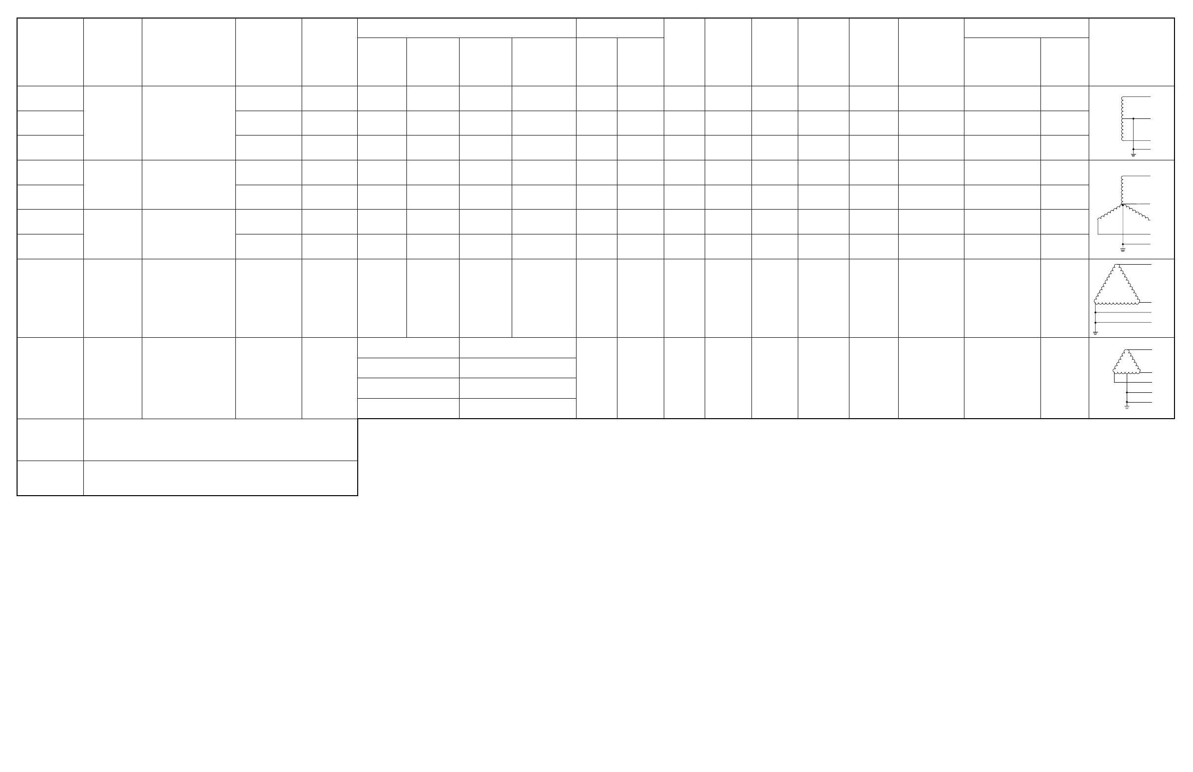
 1
1
 2
2


Legrand 36456902V1 Operating instructions
Pass and Seymour RW500BWCC4 Installation guide
Pass and Seymour RW500UWCC4 Installation guide
Charles 93-SS50/100-A Owner's manual
Siemens TPSA9040 User manual
Toshiba TVS-XT140-120 User manual
 HPM LOL004KWE User manual
Emerson LPGE Series User manual
GE TR5451 User manual
 Total Protection Solutions 200 Operating Instructions Manual
Commax DRC-40KA Owner's manual
FSR SG-120HW Installation guide

