CTC Union FMC-10/100I series Installation guide
- Category
- Network media converters
- Type
- Installation guide

Installation Instructions for FMC-10/100I
10/100BASE-T/TX to 100BASE-FX
In-band Managed Fiber Media Converters
Description
The FMC-10/100I is a media converter for 10Base-T or 100Base-TX, data transmission over optical
fiber media depending on your specific network needs. All media converters are available with either
multi-mode or single-mode optical transceivers and with connectors for SC, ST or FC. In single mode,
WDM (Wave Division Multiplexing with SC connector) is also available in 20, 40, 60, or 80Km reach,
which will provide the ability to transmit and receive data using only a single optical fiber. When the
FMC-10/100I is connected with the FRM220 rack, then it features with In band management, the
converter can be monitored, configured and controlled the activity of each port for both local or
remote sides. For the UTP side, auto-negotiation is default. You may set data rate to 10Mbps or
100Mbps and duplex mode to full or half only. The Fiber Transceiver Converters give you the freedom
to extend your 10/100Mbps cabling distance by allowing connectivity up to 120 kilometers. Six LED
indicators signal the power status of the converter, UTP port speed, duplex status and Link/Act and
FX port Link/Act and FEF (Far End Fault).
V.: 1.1
Specifications
Standard
IEEE802.3 10BASE-T, IEEE802.3u 100BASE-TX, l00BASE-FX (Fast Fiber, 100Mbps)
Supports Full Duplex Ethernet mode (200Mbps),
FMC-10/100I family supports transmission of Ethernet packet up to 2046Bytes in size.
10/100BASE-TX RJ-45 Connectors
One RJ-45 connector is provided for connection to MDI-X (To PC) or MDI (To HUB) equipment.
Auto MDI-X allows all UTP connections to be made using only a common straight-through UTP cable.
MDI-X type MDI typeRJ-45 Pin
1
2
3
6
Rx+
Rx -
Tx+
Tx -
Tx+
Rx+
100BASE-TX UTP Cable
Cable type: 100Base-Tx; Category 5 or better
Maximum cable distance: 100 meters (328 feet)
Fiber Optic Connectors
For FMC-10/100I: Two connectors are provided for fiber optic cable connection.
One is for transmission and the other is for reception of optical data
For FMC-10/100I WDM: One connector is provided for fiber optic cable connection.
For both transmission and reception of optical data.
*Please note that transceiver type A must connect to transceiver type B for proper fiber linking.
Environment
Temperature : 0
o
C –50
o
C
Humidity: 5-95% non condensing
Dimension
73.4mm x 108mm x 23mm
( W x D x H )
Power
AC adaptor +12V / 400mA
Tx -
Rx -
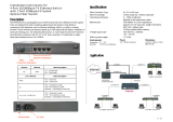
Fiber
Connections
Ethernet
Connections
DC Jack
LEDs
Features
*Auto Negotiation or Manual mode in TP port
*Link fault pass through (LFP) function
*Forward 2046 bytes packets in switch mode
*Forward 9K jumbo packets in convert mode
*Compatible with FRM220 Chassis In Band Management
*Bandwidth control (32K or 512Kbps x N)
*Support operation mode : Convert and Switch mode
*Support local or remote Monitor
(Link/Speed/Duplex/Power)
*Support local or remote Configure
(Speed/Duplex/port disable/Operating mode
*Support remote CPE power fail detect
*Provide Auto Laser Shutdown (ALS) function
*Support On-Line F/W upgrade (remote)
F
E
F
F
E
F
FULL FEF

V.: 1.1
LED Indicators
LED Function State Status
Power indicatorOn
Fiber link & activity
Far End Fault
Mode display
Mode display
Ethernet link & activity
On
Off
On
Off
Blinking
On
Off
On
Off
On
Off
On
Off
Blinking
Converter has power.
Converter has no power.
The fiber link is ok.
No link or the link is faulty.
Receiving data on the fiber.
Far end is experiencing link fault.
No fault.
Ethernet operates in 100Mbps
Ethernet operates in 10Mbps
Or no devices attached.
Full duplex mode (200mbps).
Half duplex mode (100mbps).
The UTP link is ok.
No link or the link is faulty.
Receiving data on Ethernet.
PWR
FX link/Act
FEF
100
Full
TX link/Act
100
PWR
FULL
FEE
Link/Act
Link/Act
TX FX
Installation
Connect the Ethernet cable to the Fiber Media Converter. The converter will sense whether to operate in Full or
Half mode and will be indicated on the LED. Follow the connection examples below. Install the fiber converter
with the AC power adapter provided (+12VDC, 400mA) and connect the adapter to an AC outlet.
Connections
The following example illustrates the connection scheme when connecting from a 100BASE-TX port of one
HUB to a 100BASE-FX port of another HUB through the fiber converter.
The following example illustrates the connection scheme when connecting from a 100BASE-TX port of
one HUB to a 100BASE-TX Network Interface Card (NIC) in a computer through the fiber converter.
100BASE-FX Fiber
Connection
100BASE-TX UTP
straight connection
Fiber Cable
Full Duplex
Use RJ-45 jack
to HUB connection
Full Duplex
100BASE-TX UTP
straight connection
100BASE-TX UTP
straight connection
Use RJ-45 jack to PC connection
Fiber Cable
Full Duplex
Use RJ-45 jack
to HUB connection
Link-Fault-Pass through (LFP) Application Note
When ‘link fault pass through’function is enabled, link status on TX port will inform the FX port of the
same device and vice versa. From the link fault pass through explanation in the figure below, if link fail
occurrson TX port (1), the local FX port sends non-idle pattern to notify the remote FX port (2). The
remote FX port then forces its TX port to link failed after receiving the non-idle pattern (4). This
mechanism will alert the link fault status of local TX port to the remote converter's TX port, and the link
status of the remote TX port will become down. Link status LED will also be off for both. Link Fault Pass
through is enabled by setting DIP switch 4 (ON).
Figure: Explanation of LFP
Fiber
local remote
UTP
UTP
Converter BConverter A
Switch or PCSwitch or PC
(1) TP port link failed (3) Fiber port gets remote link fault information
(5) Remote TP link is off
(4) TP link fail(2) Fiber port sends non-idle pattern
WARNING
WARNING
This is a Class A product. In a domestic environment this product may cause radio interference in which case
the user may be required to take adequate measures.
CE NOTICE
Marking by the symbol CE indicates compliance of this equipment to the EMC directive of the European Community.
Such marking is indicative that this equipment meets or exceeds the following technical standards:
EN 55022:1994/A1:1995/A2:1997 Class A and EN61000-3-2:1995, EN61000-3-3:1995 and EN50082-1:1997
This equipment has been tested and found to comply with the limits for a Class A digital device, pursuant to Part 15 of the FCC Rules. These limits are
designed to provide reasonable protection against harmful interference when the equipment is operated in a commercial environment. This
equipment generates, uses, and can radiate radio frequency energy and if not installed and used in accordance with the instruction manual may
cause harmful interference in which case the user will be required to correct the interference at his own expense. NOTICE: (1) The changes or
modifications not expressively approved by the party responsible for compliance could void the user's authority to operate the equipment. (2)
Shielded interface cables and AC power cord, if any, must be used in order to comply with the emission limits.
CISPR PUB.22 Class A COMPLIANCE:
This device complies with EMC directive of the European Community and meets or exceeds the following technical standard. EN 55022 -Limits and
Methods of Measurement of Radio Interference Characteristics of Information Technology Equipment. This device complies with CISPR Class A.
-
 1
1
-
 2
2


CTC Union FMC-10/100I series Installation guide
- Category
- Network media converters
- Type
- Installation guide
Ask a question and I''ll find the answer in the document
Finding information in a document is now easier with AI
Related papers
-
CTC Union FRM220-100S User manual
-
-
-
-
-
-
-
-
-
Other documents
-
Dante DFO38012X Operating instructions
-
Lindy 100Base-TX User manual
-
KTI Networks Ethernet Media Converter User manual
-
 CTC Store FSW2104 User manual
-
 StarTech.com Ethernet Fiber Converter Installation guide
-
 StarTech.com Ethernet Fiber Media Converter Installation guide
-
Intellisystem IT-PMC-1200 Owner's manual
-
Accton Technology Edge-corE EC3802-WDM User manual
-
Planet FST-806A20/806B20 User manual
-
Repotec RP-130GPFP Owner's manual


