Gigabyte GA-78LMT-S2PT Owner's manual
- Category
- Motherboards
- Type
- Owner's manual

GA-78LMT-S2PT
User's Manual
Rev. 4201
12ME-78LMT2T-4201R
To reduce the impacts on global warming, the packaging materials of this product
are recyclable and reusable. GIGABYTE works with you to protect the environment.
For more product details, please visit GIGABYTE's website.

Copyright
© 2016 GIGA-BYTE TECHNOLOGY CO., LTD. All rights reserved.
The trademarks mentioned in this manual are legally registered to their respective owners.
Disclaimer
Information in this manual is protected by copyright laws and is the property of GIGABYTE.
Changes to the specications and features in this manual may be made by GIGABYTE without prior notice.
No part of this manual may be reproduced, copied, translated, transmitted, or published in any form or
by any means without GIGABYTE's prior written permission.
In order to assist in the use of this product, carefully read the User's Manual.
For product-related information, check on our website at: http://www.gigabyte.com
Identifying Your Motherboard Revision
The revision number on your motherboard looks like this: "REV: X.X." For example, "REV: 1.0" means
the revision of the motherboard is 1.0. Check your motherboard revision before updating motherboard
BIOS, drivers, or when looking for technical information.
Example:
Motherboard
GA-78LMT-S2PT
Jan. 8, 2016
Jan. 8, 2016
Motherboard
GA-78LMT-S2PT

- 3 -
Table of Contents
GA-78LMT-S2PT Motherboard Layout ............................................................................4
Chapter 1 Hardware Installation .....................................................................................5
1-1 Installation Precautions .................................................................................... 5
1-2 ProductSpecications ...................................................................................... 6
1-3 Installing the CPU ............................................................................................ 8
1-4 Installing the Memory ....................................................................................... 8
1-5 Installing an Expansion Card ........................................................................... 9
1-6 Back Panel Connectors .................................................................................... 9
1-7 Internal Connectors ........................................................................................ 11
Chapter 2 BIOS Setup ..................................................................................................18
2-1 Startup Screen ............................................................................................... 18
2-2 The Main Menu .............................................................................................. 19
2-3 MB Intelligent Tweaker(M.I.T.) ........................................................................ 20
2-4 Standard CMOS Features .............................................................................. 24
2-5 Advanced BIOS Features .............................................................................. 25
2-6 Integrated Peripherals .................................................................................... 28
2-7 Power Management Setup ............................................................................. 30
2-8 PnP/PCICongurations ................................................................................. 32
2-9 PC Health Status ............................................................................................ 32
2-10 Load Fail-Safe Defaults .................................................................................. 33
2-11 Load Optimized Defaults ................................................................................ 34
2-12 Set Supervisor/User Password ...................................................................... 34
2-13 Save & Exit Setup .......................................................................................... 35
2-14 Exit Without Saving ........................................................................................ 35
Chapter 3 Appendix ......................................................................................................36
3-1 Drivers Installation .......................................................................................... 36
3-2 ConguringaRAIDSet .................................................................................. 36
RegulatoryStatements .............................................................................................. 38
Contact Us ................................................................................................................ 40

- 4 -
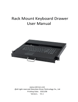
GA-78LMT-S2PT Motherboard Layout
* The box contents above are for reference only and the actual items shall depend on the product package you
obtain. The box contents are subject to change without notice.
Box Contents
5GA-78LMT-S2PT motherboard
5Motherboard driver disk 5Two SATA cables
5One IDE cable 5User's Manual
5I/O Shield
KB_MS
CPU_FAN
Socket AM3+ ATX
IDE
GA-78LMT-S2PT
F_AUDIO
AUDIO
B_BIOS
DDR3_1
DDR3_2
BAT
F_PANEL
ATX_12V
SATA2
2 3
0 1
SATA2
4 5
R_USB
CODEC
M_BIOS
COM
LPT
VGA
USB_LAN
PCIEX16
PCIEX1
PCI
F_USB1F_USB2
SYS_FAN
CLR_CMOS
Realtek®
GbE LAN
iTE®
Super I/O
AMD 760G
AMD SB710

- 5 -
Chapter 1 Hardware Installation
1-1 Installation Precautions
The motherboard contains numerous delicate electronic circuits and components which can become
damaged as a result of electrostatic discharge (ESD). Prior to installation, carefully read the user's
manual and follow these procedures:
•Prior to installation, make sure the chassis is suitable for the motherboard.
•Prior to installation, do not remove or break motherboard S/N (Serial Number) sticker or
warranty sticker provided by your dealer. These stickers are required for warranty validation.
•Always remove the AC power by unplugging the power cord from the power outlet before
installing or removing the motherboard or other hardware components.
•When connecting hardware components to the internal connectors on the motherboard, make
sure they are connected tightly and securely.
•When handling the motherboard, avoid touching any metal leads or connectors.
•It is best to wear an electrostatic discharge (ESD) wrist strap when handling electronic
components such as a motherboard, CPU or memory. If you do not have an ESD wrist strap,
keepyourhandsdryandrsttouchametalobjecttoeliminatestaticelectricity.
•Prior to installing the motherboard, please have it on top of an antistatic pad or within an
electrostatic shielding container.
•Before connecting or unplugging the power supply cable from the motherboard, make sure
the power supply has been turned off.
•Before turning on the power, make sure the power supply voltage has been set according to
the local voltage standard.
•Before using the product, please verify that all cables and power connectors of your hardware
components are connected.
•To prevent damage to the motherboard, do not allow screws to come in contact with the
motherboard circuit or its components.
•Make sure there are no leftover screws or metal components placed on the motherboard or
within the computer casing.
•Do not place the computer system on an uneven surface.
•Do not place the computer system in a high-temperature or wet environment.
•Turning on the computer power during the installation process can lead to damage to system
components as well as physical harm to the user.
•If you are uncertain about any installation steps or have a problem related to the use of the
product,pleaseconsultacertiedcomputertechnician.
•If you use an adapter, extension power cable, or power strip, ensure to consult with its installation
and/or grounding instructions.

- 6 -
1-2 ProductSpecications
CPU AM3+ Socket:
- AMD AM3+ FX processor
- AMD AM3 Phenom™ II processor/ AMD Athlon™ II processor
(Go to GIGABYTE's website for the latest CPU support list.)
HyperTransport
Bus
HyperTransport™ 3.0
Support for up to 5200 MT/s
Chipset North Bridge: AMD 760G
South Bridge: AMD SB710
Memory 2xDDR3DIMMsocketssupportingupto16GBofsystemmemory
* Due to a Windows 32-bit operating system limitation, when more than 4 GB of physical
memory is installed, the actual memory size displayed will be less than the size of
the physical memory installed.
Dual channel memory architecture
SupportforDDR31600(OC)/1333/1066/800MHzmemorymodules
(Go to GIGABYTE's website for the latest supported memory speeds and
memory modules.)
Onboard
Graphics
North Bridge:
- 1 x D-Sub port
Audio Realtek® HD codec
HighDenitionAudio
2/4/5.1/7.1-channel
* Tocongure7.1-channelaudio,youhavetouseanHDfrontpanelaudiomodule
and enable the multi-channel audio feature through the audio driver.
LAN Realtek® GbE LAN chip (10/100/1000 Mbit)
Expansion Slots 1 x PCI Express x16 slot, running at x16
1 x PCI Express x1 slot
(All PCI Express slots conform to the PCI Express 2.0 standard.)
1 x PCI slot
Storage Interface South Bridge:
- 1 x IDE connector supporting ATA-133/100/66/33 and up to 2 IDE devices
- 6 x SATA 3Gb/s connectors
- SupportforSATARAID0,RAID1,RAID10,andJBOD
USB South Bridge:
- 8 x USB 2.0/1.1 ports (4 ports on the back panel, 4 ports available through
the internal USB headers)
Internal
Connectors
1 x 24-pin ATX main power connector
1 x 4-pin ATX 12V power connector
1 x IDE connector
6 x SATA 3Gb/s connectors
2 x USB 2.0/1.1 headers
1 x CPU fan header
1 x system fan header
1 x front panel header
1 x front panel audio header
1 x Clear CMOS jumper

- 7 -
Back Panel
Connectors
1 x PS/2 keyboard port
1 x PS/2 mouse port
1 x serial port
1 x parallel port
1 x D-Sub port
4 x USB 2.0/1.1 ports
1xRJ-45port
3 x audio jacks (Line In, Line Out, Microphone)
I/O Controller iTE® I/O Controller Chip
Hardware
Monitor
System voltage detection
CPU/System temperature detection
CPU/System fan speed detection
CPU overheating warning
CPU/System fan fail warning
CPU fan speed control
* Whether the CPU fan speed control function is supported will depend on the CPU
cooler you install.
BIOS 2x16Mbitash
UseoflicensedAWARDBIOS
Support for DualBIOS™
PnP 1.0a, DMI 2.0, SM BIOS 2.4, ACPI 1.0b
Unique Features Support for @BIOS
Support for Q-Flash
Support for Xpress Install
Support for EasyTune
* Available functions in EasyTune may differ by motherboard model.
SupportforSmartRecovery2
Support for Auto Green
Support for ON/OFF Charge
Support for 3TB+ Unlock
Support for Q-Share
Bundled
Software Norton® Internet Security (OEM version)
Operating
System Support for Windows 7/XP
Form Factor Micro ATX Form Factor; 24.4cm x 20.6cm
* GIGABYTEreservestherighttomakeanychangestotheproductspecicationsandproduct-relatedinformationwithout
prior notice.
* Please visit the Support\Utility List page on GIGABYTE's website to download the latest version of apps.

- 8 -
1-3 Installing the CPU
Installing the CPU
Locate the pin one (denoted by a small triangle) of the CPU socket and the CPU.
ReadthefollowingguidelinesbeforeyoubegintoinstalltheCPU:
•Make sure that the motherboard supports the CPU.
(Go to GIGABYTE's website for the latest CPU support list.)
•Always turn off the computer and unplug the power cord from the power outlet before installing the
CPU to prevent hardware damage.
•Locate the pin one of the CPU. The CPU cannot be inserted if oriented incorrectly.
•Apply an even and thin layer of thermal grease on the surface of the CPU.
•Do not turn on the computer if the CPU cooler is not installed, otherwise overheating and damage
of the CPU may occur.
•SettheCPUhostfrequencyinaccordancewiththeCPUspecications.Itisnotrecommended
thatthesystembusfrequencybesetbeyondhardwarespecicationssinceitdoesnotmeetthe
standard requirements for the peripherals. If you wish to set the frequency beyond the standard
specications,pleasedosoaccordingtoyourhardwarespecicationsincludingtheCPU,graphics
card, memory, hard drive, etc.
AM3+/AM3 CPU
A Small Triangle Marking
Denotes CPU Pin One
AM3+ Socket
A Small Triangle Mark
Denotes Pin One of the
Socket
1-4 Installing the Memory
DualChannelMemoryConguration
ThismotherboardprovidestwoDDR3memorysocketsandsupports Dual Channel Technology. After the memory
isinstalled,theBIOSwillautomaticallydetectthespecicationsandcapacityofthememory.EnablingDual
Channel memory mode will double the original memory bandwidth.
Readthefollowingguidelinesbeforeyoubegintoinstallthememory:
•Make sure that the motherboard supports the memory. It is recommended that memory of the
same capacity, brand, speed, and chips be used.
(Go to GIGABYTE's website for the latest supported memory speeds and memory modules.)
•Always turn off the computer and unplug the power cord from the power outlet before installing the
memory to prevent hardware damage.
•Memory modules have a foolproof design. A memory module can be installed in only one direction.
If you are unable to insert the memory, switch the direction.

- 9 -
Due to CPU limitations, read the following guidelines before installing the memory in Dual Channel mode.
1. DualChannelmodecannotbeenabledifonlyoneDDR3memorymoduleisinstalled.
2. When enabling Dual Channel mode with two memory modules, it is recommended that memory of
the same capacity, brand, speed, and chips be used for optimum performance.
1-5 Installing an Expansion Card
Readthefollowingguidelinesbeforeyoubegintoinstallanexpansioncard:
•Make sure the motherboard supports the expansion card. Carefully read the manual that came
with your expansion card.
•Always turn off the computer and unplug the power cord from the power outlet before installing an
expansion card to prevent hardware damage.
ThetwoDDR3memorysocketsaredividedintotwochannelsandeachchannelhasonememorysocketas
following:
ChannelA:DDR3_1
ChannelB:DDR3_2
1-6 Back Panel Connectors
PS/2 Keyboard and PS/2 Mouse Port
Use the upper port (green) to connect a PS/2 mouse and the lower port (purple) to connect a PS/2 keyboard.
Serial Port
Use the serial port to connect devices such as a mouse, modem or other peripherals.
Parallel Port
Use the parallel port to connect devices such as a printer, scanner and etc. The parallel port is also called
a printer port.
D-Sub Port
The D-Sub port supports a 15-pin D-Sub connector. Connect a monitor that supports D-Sub connection
to this port.
USB 2.0/1.1 Port
TheUSBportsupportstheUSB2.0/1.1specication.UsethisportforUSBdevices.
RJ-45 LAN Port
The Gigabit Ethernet LAN port provides Internet connection at up to 1 Gbps data rate. The following
describes the states of the LAN port LEDs.
Activity LED
Connection/
Speed LED
LAN Port
Activity LED:Connection/Speed LED:
State Description
Orange 1 Gbps data rate
Green 100 Mbps data rate
Off 10 Mbps data rate
State Description
Blinking Data transmission or receiving is occurring
Off No data transmission or receiving is occurring

- 10 -
•Whenremovingthecableconnectedtoabackpanelconnector,rstremovethecablefromyour
device and then remove it from the motherboard.
•When removing the cable, pull it straight out from the connector. Do not rock it side to side to prevent
an electrical short inside the cable connector.
Line In Jack (Blue)
The line in jack. Use this audio jack for line in devices such as an optical drive, walkman, etc.
Line Out Jack (Green)
The line out jack. Use this audio jack for a headphone or 2-channel speaker. This jack can be used to
connectfrontspeakersina4/5.1/7.1-channelaudioconguration.
Mic In Jack (Pink)
The Mic in jack. Microphones must be connected to this jack.
Tocongure7.1-channelaudio,youhavetouseanHDfrontpanelaudiomoduleandenablethe
multi-channel audio feature through the audio driver. Please visit GIGABYTE's website for more
software information.

- 11 -
1-7 Internal Connectors
Readthefollowingguidelinesbeforeconnectingexternaldevices:
•First make sure your devices are compliant with the connectors you wish to connect.
•Before installing the devices, be sure to turn off the devices and your computer. Unplug the power
cord from the power outlet to prevent damage to the devices.
•After installing the device and before turning on the computer, make sure the device cable has
been securely attached to the connector on the motherboard.
1) ATX_12V
2) ATX
3) CPU_FAN
4) SYS_FAN
5) SATA2 0/1/2/3/4/5
6) F_PANEL
7) F_AUDIO
8) F_USB1/F_USB2
9) IDE
10) CLR_CMOS
11) BAT
1
2
9
5
3
104
7
11
5
8 6

- 12 -
ATX:
1/2) ATX_12V/ATX (2x2 12V Power Connector and 2x12 Main Power Connector)
With the use of the power connector, the power supply can supply enough stable power to all the components
onthemotherboard.Beforeconnectingthepowerconnector,rstmakesurethepowersupplyisturned
off and all devices are properly installed. The power connector possesses a foolproof design. Connect the
power supply cable to the power connector in the correct orientation. The 12V power connector mainly
supplies power to the CPU. If the 12V power connector is not connected, the computer will not start.
To meet expansion requirements, it is recommended that a power supply that can withstand high
power consumption be used (500W or greater). If a power supply is used that does not provide the
required power, the result can lead to an unstable or unbootable system.
ATX_12V:
Pin No. Denition
1 GND
2 GND
3 +12V
4 +12V
Pin No. Denition Pin No. Denition
1 3.3V 13 3.3V
2 3.3V 14 -12V
3 GND 15 GND
4 +5V 16 PS_ON (soft On/Off)
5 GND 17 GND
6 +5V 18 GND
7 GND 19 GND
8 Power Good 20 NC
9 5VSB (stand by +5V) 21 +5V
10 +12V 22 +5V
11 +12V (Only for 2x12-pin ATX) 23 +5V (Only for 2x12-pin ATX)
12 3.3V (Only for 2x12-pin ATX) 24 GND (Only for 2x12-pin ATX)
DEBUG
PORT
G.QBOFM
131
2412
ATX
ATX_12V
1
3
2
4

- 13 -
3/4) CPU_FAN/SYS_FAN (Fan Headers)
The motherboard has a 4-pin CPU fan header (CPU_FAN), and a 3-pin system fan header (SYS_FAN).
Most fan headers possess a foolproof insertion design. When connecting a fan cable, be sure to connect it
in the correct orientation (the black connector wire is the ground wire). The speed control function requires
the use of a fan with fan speed control design. For optimum heat dissipation, it is recommended that a
system fan be installed inside the chassis.
•Be sure to connect fan cables to the fan headers to prevent your CPU and system from overheating. Overheating
may result in damage to the CPU or the system may hang.
•Thesefanheadersarenotcongurationjumperblocks.Donotplaceajumpercapontheheaders.
CPU_FAN: SYS_FAN:
Pin No. Denition
1 GND
2 +12V
3 Sense
4 Speed Control
Pin No. Denition
1 GND
2 +12V
3 Sense
5) SATA2 0/1/2/3/4/5 (SATA 3Gb/s Connectors, Controlled by AMD SB710 South Bridge)
The SATA connectors conform to SATA 3Gb/s standard and are compatible with SATA 1.5Gb/s standard.
EachSATAconnectorsupportsasingleSATAdevice.TheAMDSB710SouthBridgesupportsRAID0,
RAID1,RAID10,andJBOD.RefertoChapter4,"ConguringaRAIDSet,"forinstructionsonconguring
aRAIDarray.
Pin No. Denition
1 GND
2 TXP
3 TXN
4 GND
5RXN
6RXP
7 GND
CPU_FAN SYS_FAN
DEBUG
PORT
G.QBOFM
11
Toenablehot-pluggingfortheSATAports,refertoChapter2,"BIOSSetup,""Peripherals\SATA
Conguration,"formoreinformation.
7
1
DEBUG
PORT
G.QBOFM
DEBUG
PORT
G.QBOFM
1
1
7
7
DEBUG
PORT
G.QBOFM
DEBUG
PORT
G.QBOFM
DEBUG
PORT
G.QBOFM
DEBUG
PORT
G.QBOFM
2 3
0 1
5
4
SATA2

- 14 -
The front panel design may differ by chassis. A front panel module mainly consists of power switch,
reset switch, power LED, hard drive activity LED, speaker and etc. When connecting your chassis
front panel module to this header, make sure the wire assignments and the pin assignments are
matched correctly.
6) F_PANEL (Front Panel Header)
Connect the power switch, reset switch, speaker, chassis intrusion switch/sensor and system status indicator
on the chassis to this header according to the pin assignments below. Note the positive and negative pins
before connecting the cables.
System Status LED
S0 On
S3/S4/S5 Off
•PW (Power Switch):
Connects to the power switch on the chassis front panel. You may
congure the way to turn off your system using thepower switch
(refertoChapter2,"BIOSSetup,""Power Management," formore
information).
•MSG/PWR_LED (Power LED):
Connects to the power status indicator
on the chassis front panel. The LED is on
when the system is operating. The LED is
off when the system is in S3/S4 sleep state
or powered off (S5).
•SPEAK (Speaker):
Connects to the speaker on the chassis front panel. The system reports system startup status by issuing
a beep code. One single short beep will be heard if no problem is detected at system startup.
•HD (Hard Drive Activity LED):
Connects to the hard drive activity LED on the chassis front panel. The LED is on when the hard drive
is reading or writing data.
•RES (ResetSwitch):
Connects to the reset switch on the chassis front panel. Press the reset switch to restart the computer
if the computer freezes and fails to perform a normal restart.
•CI (Chassis Intrusion Header):
Connects to the chassis intrusion switch/sensor on the chassis that can detect if the chassis cover has
been removed. This function requires a chassis with a chassis intrusion switch/sensor.
•NC: No connection.
MSG-
PW-
SPEAK+
SPEAK-
MSG+
PW+
HD-
RES+
HD+
RES-
Hard Drive
Activity LED
Reset
Switch
DEBUG
PORT
G.QBOFM
Power LED
1
2
19
20
CI-
CI+
Power LED
Chassis Intrusion
Header
Power Switch Speaker
NC
NC
PWR_LED-
PWR_LED-
PWR_LED+

- 15 -
7) F_AUDIO (Front Panel Audio Header)
The front panel audio header supports Intel®HighDenitionaudio(HD)andAC'97audio.Youmayconnect
your chassis front panel audio module to this header. Make sure the wire assignments of the module connector
match the pin assignments of the motherboard header. Incorrect connection between the module connector
and the motherboard header will make the device unable to work or even damage it.
•The front panel audio header supports HD audio by default.
•Audio signals will be present on both of the front and back panel audio connections
simultaneously.
•Some chassis provide a front panel audio module that has separated connectors on each wire
instead of a single plug. For information about connecting the front panel audio module that
has different wire assignments, please contact the chassis manufacturer.
For HD Front Panel Audio: For AC'97 Front Panel Audio:
Pin No. Denition
1 MIC2_L
2 GND
3MIC2_R
4 -ACZ_DET
5LINE2_R
6 Sense
7 FAUDIO_JD
8 No Pin
9 LINE2_L
10 Sense
Pin No. Denition
1 MIC
2 GND
3 MIC Power
4 NC
5LineOut(R)
6 NC
7 NC
8 No Pin
9 Line Out (L)
10 NC
8) F_USB1/F_USB2 (USB 2.0/1.1 Headers)
TheheadersconformtoUSB2.0/1.1specication.EachUSBheadercanprovidetwoUSBportsviaan
optional USB bracket. For purchasing the optional USB bracket, please contact the local dealer.
•Do not plug the IEEE 1394 bracket (2x5-pin) cable into the USB header.
•Prior to installing the USB bracket, be sure to turn off your computer and unplug the power cord
from the power outlet to prevent damage to the USB bracket.
Pin No. Denition
1 Power (5V)
2 Power (5V)
3 USB DX-
4 USB DY-
5 USB DX+
6 USB DY+
7 GND
8 GND
9 No Pin
10 NC
10
9
2
1
10
9
2
1

- 16 -
10) CLR_CMOS (Clear CMOS Jumper)
UsethisjumpertocleartheCMOSvalues(e.g.dateinformationandBIOScongurations)andresetthe
CMOS values to factory defaults. To clear the CMOS values, use a metal object like a screwdriver to touch
the two pins for a few seconds.
9) IDE (IDE Connector)
The IDE connector supports up to two IDE devices such as hard drives and optical drives. Before attaching
the IDE cable, locate the foolproof groove on the connector. If you wish to connect two IDE devices, remember
to set the jumpers and the cabling according to the role of the IDE devices (for example, master or slave).
(Forinformationaboutconguringmaster/slavesettingsfortheIDEdevices,readtheinstructionsfromthe
device manufacturers.)
•Always turn off your computer and unplug the power cord from the power outlet before clearing
the CMOS values.
•After system restart, go to BIOS Setup to load factory defaults (select Load Optimized Defaults) or
manuallyconguretheBIOSsettings(refertoChapter2,"BIOSSetup,"forBIOScongurations).
Open: Normal
Short: Clear CMOS Values
2
40
1
39

- 17 -
11) BAT (Battery)
Thebatteryprovidespowertokeepthevalues(suchasBIOScongurations,date,andtimeinformation)
intheCMOSwhenthecomputeristurnedoff.Replacethebatterywhenthebatteryvoltagedropstoalow
level, or the CMOS values may not be accurate or may be lost.
You may clear the CMOS values by removing the battery:
1. Turn off your computer and unplug the power cord.
2. Gently remove the battery from the battery holder and wait for one minute. (Or use a metal
object like a screwdriver to touch the positive and negative terminals of the battery holder,
making them short for 5 seconds.)
3. Replacethebattery.
4. Plug in the power cord and restart your computer.
•Always turn off your computer and unplug the power cord before replacing the battery.
•Replacethebatterywithanequivalentone.Dangerofexplosionifthebatteryisreplacedwith
an incorrect model.
•Contact the place of purchase or local dealer if you are not able to replace the battery by yourself
or uncertain about the battery model.
•When installing the battery, note the orientation of the positive side (+) and the negative side (-)
of the battery (the positive side should face up).
•Used batteries must be handled in accordance with local environmental regulations.

- 18 -
To access the BIOS Setup program, press the <Delete> key during the POST when the power is turned on.
To see more advanced BIOS Setup menu options, you can press <Ctrl> + <F1> in the main menu of the BIOS
Setup program.
To upgrade the BIOS, use either the GIGABYTE Q-Flash or @BIOS utility.
•Q-Flash allows the user to quickly and easily upgrade or back up BIOS without entering the operating system.
•@BIOS is a Windows-based utility that searches and downloads the latest version of BIOS from the Internet
and updates the BIOS.
Chapter 2 BIOS Setup
•BecauseBIOSashingispotentiallyrisky,ifyoudonotencounterproblemsusingthecurrent
versionofBIOS,itisrecommendedthatyounotashtheBIOS.ToashtheBIOS,doitwith
caution.InadequateBIOSashingmayresultinsystemmalfunction.
•It is recommended that you not alter the default settings (unless you need to) to prevent system
instability or other unexpected results. Inadequately altering the settings may result in system's
failure to boot. If this occurs, try to clear the CMOS values and reset the board to default values.
(Refertothe"LoadOptimizedDefaults"sectioninthischapterorintroductionsofthebattery/
clearing CMOS jumper in Chapter 1 for how to clear the CMOS values.)
2-1 Startup Screen
The following screens may appear when the computer boots.
A. The LOGO Screen (Default):
B. The POST Screen
Motherboard Model
BIOS Version
Award Modular BIOS v6.00PG
Copyright (C) 1984-2012, Award Software, Inc.
GA-78LMT-S2PT E3
.
.
.
.
<DEL>:BIOSSetup<F9>:XpressRecovery2<F12>:BootMenu<End>:Qflash
12/15/2015-RS780L-SB710-7A66CG0ZC-00
Function Keys
Function Keys

- 19 -
•IfyoudonotndthesettingsyouwantintheMainMenuorasubmenu,press<Ctrl>+<F1>to
access more advanced options.
•When the system is not stable as usual, select the Load Optimized Defaults item to set your
system to its defaults.
•The BIOS Setup menus described in this chapter are for reference only and may differ by BIOS
version.
The Functions of the <F11> and <F12> keys (For the Main Menu Only)
`F11: Save CMOS to BIOS
ThisfunctionallowsyoutosavethecurrentBIOSsettingstoaprole.Youcancreateupto8proles
(Prole1-8)andnameeachprole.Firstentertheprolename(toerasethedefaultprolename,usethe
SPACE key) and then press <Enter> to complete.
`F12: Load CMOS from BIOS
If your system becomes unstable and you have loaded the BIOS default settings, you can use this function
toloadtheBIOSsettingsfromaprolecreatedbefore,withoutthehasslesofreconguringtheBIOS
settings.Firstselecttheproleyouwishtoload,thenpress<Enter>tocomplete.
2-2 The Main Menu
Once you enter the BIOS Setup program, the Main Menu (as shown below) appears on the screen. Use arrow
keys to move among the items and press <Enter> to accept or enter a sub-menu.
(Sample BIOS Version: E3)
CMOS Setup Utility-Copyright (C) 1984-2012 Award Software
Change CPU's Clock & Voltage
`MB Intelligent Tweaker(M.I.T.)
`Standard CMOS Features
`Advanced BIOS Features
`Integrated Peripherals
`Power Management Setup
`PnP/PCI Congurations
`PC Health Status
Load Fail-Safe Defaults
Load Optimized Defaults
Set Supervisor Password
Set User Password
Save & Exit Setup
Exit Without Saving
ESC: Quit : Select Item F11: Save CMOS to BIOS
F8: Q-Flash F10: Save & Exit Setup F12: Load CMOS from BIOS

- 20 -
2-3 MB Intelligent Tweaker(M.I.T.)
Whether the system will work stably with the overclock/overvoltage settings you made is dependent
onyouroverallsystemcongurations.Incorrectlydoingoverclock/overvoltagemayresultindamage
to CPU, chipset, or memory and reduce the useful life of these components. This page is for advanced
users only and we recommend you not to alter the default settings to prevent system instability or
other unexpected results. (Inadequately altering the settings may result in system's failure to boot. If
this occurs, clear the CMOS values and reset the board to default values.)
(Note) This item is present only when you install a CPU that supports this feature.
CMOS Setup Utility-Copyright (C) 1984-2012 Award Software
IGX Conguration
: Move Enter: Select +/-/PU/PD: Value F10: Save ESC: Exit F1: General Help
F5: Previous Values F6: Fail-Safe Defaults F7: Optimized Defaults
Item Help
Menu Level ``
Internal Graphics Mode [UMA]
UMA Frame Buffer Size [Auto]
x Surround View Disabled
VGA Core Clock control [Auto]
x VGA Core Clock(MHz) 350
&IGXConguration
&Internal Graphics Mode
Allows you to determine whether to allocate system memory for the onboard graphics controller.
Disabled Disables the onboard graphics controller.
UMA Allocates memory for the onboard graphics controller from the system memory. (Default)
&UMA Frame Buffer Size
Frame buffer size is the total amount of system memory allocated solely for the onboard graphics controller.
MS-DOS, for example, will use only this memory for display. Options are: Auto (default), 128MB, 256MB,
512MB, 1024MB.
CMOS Setup Utility-Copyright (C) 1984-2012 Award Software
MB Intelligent Tweaker(M.I.T.)
`IGX Conguration [Press Enter]
CPU Clock Ratio [Auto] 3500Mhz
CPU NorthBridge Freq. [Auto] 1800Mhz
Core Performance Boost (Note) [Enabled]
CPB Ratio (Note) [Auto] 4100Mhz
Turbo CPB (Note) [Disabled]
CPU Host Clock Control [Auto]
x CPU Frequency(MHz) 200
PCIE Clock(MHz) [Auto]
HT Link Width [Auto]
HT Link Frequency [Auto] 1800Mhz
Set Memory Clock [Auto]
x Memory Clock x6.66 1333Mhz
`DRAM Conguration [Press Enter]
******** System Voltage Optimized ********
System Voltage Control [Auto]
x DDR3 Voltage Auto
x CPU Voltage Control Auto
x CPU NB VID Control Auto
Normal CPU Vcore 1.3250V
Normal CPU Vcore NB 1.2000V
: Move Enter: Select +/-/PU/PD: Value F10: Save ESC: Exit F1: General Help
F5: Previous Values F6: Fail-Safe Defaults F7: Optimized Defaults
Item Help
Menu Level `
Page is loading ...
Page is loading ...
Page is loading ...
Page is loading ...
Page is loading ...
Page is loading ...
Page is loading ...
Page is loading ...
Page is loading ...
Page is loading ...
Page is loading ...
Page is loading ...
Page is loading ...
Page is loading ...
Page is loading ...
Page is loading ...
Page is loading ...
Page is loading ...
Page is loading ...
Page is loading ...
-
 1
1
-
 2
2
-
 3
3
-
 4
4
-
 5
5
-
 6
6
-
 7
7
-
 8
8
-
 9
9
-
 10
10
-
 11
11
-
 12
12
-
 13
13
-
 14
14
-
 15
15
-
 16
16
-
 17
17
-
 18
18
-
 19
19
-
 20
20
-
 21
21
-
 22
22
-
 23
23
-
 24
24
-
 25
25
-
 26
26
-
 27
27
-
 28
28
-
 29
29
-
 30
30
-
 31
31
-
 32
32
-
 33
33
-
 34
34
-
 35
35
-
 36
36
-
 37
37
-
 38
38
-
 39
39
-
 40
40


Gigabyte GA-78LMT-S2PT Owner's manual
- Category
- Motherboards
- Type
- Owner's manual
Ask a question and I''ll find the answer in the document
Finding information in a document is now easier with AI
Related papers
-
Gigabyte GA-78LMT-USB3 User manual
-
Gigabyte GA-78LMT-S2 R2 Owner's manual
-
Gigabyte GA-78LMT-S2P User manual
-
-
-
-
-
-
Gigabyte GA-M68MT-S2 Owner's manual
-
Gigabyte GA-880GM-D2H User manual