Page is loading ...

-2-
F
E
D
C
BA
BM 2610A16273 07-13_BM 2610A16273 07-13 7/30/13 2:01 PM Page 2
Page is loading ...
Page is loading ...

-5-
General Safety Rules
Read all instructions. Failure to follow all instructions
listed below may result in hazardous radiation
exposure, electric shock, fire and/or serious injury.
SAVE ALL WARNINGS AND INSTRUCTIONS
FOR FUTURE REFERENCE
The term “tool” in the warnings listed below refers to your mains-operated
(corded) tool or battery-operated (cordless) tool.
The following labels are on your laser tool for your convenience and
safety. They indicate where the laser light is emitted by the tool.
ALWAYS BE AWARE of their location when using the tool.
Do not direct the laser beam at persons or animals and
do not stare into the laser beam yourself. This tool
produces laser class 2 laser radiation and complies
with 21 CFR 1040.10 and 1040.11 except for deviations
pursuant to Laser Notice No. 50, dated June 24, 2007.
!
WARNING
BM 2610A16273 07-13_BM 2610A16273 07-13 7/30/13 2:02 PM Page 5

-6-
DO NOT remove or deface any warning or caution labels. Removing
labels increases the risk of exposure to laser radiation.
Use of controls or adjustments or performance of procedures other
than those specified in this manual, may result in hazardous
radiation exposure.
ALWAYS make sure that any bystanders in the vicinity of use are
made aware of the dangers of looking directly into the laser tool.
DO NOT place the laser tool in a position that may cause anyone to
stare into the laser beam intentionally or unintentionally. Serious eye
injury could result.
ALWAYS position the laser tool securely. Damage to the laser tool
and/or serious injury to the user could result if the laser tool fails.
ALWAYS use only the accessories that are recommended by the
manufacturer of your laser tool. Use of accessories that have been
designed for use with other laser tools could result in serious injury.
DO NOT use this laser tool for any purpose other than those outlined
in this manual. This could result in serious injury.
DO NOT leave the laser tool “ON” unattended in any operating mode.
DO NOT disassemble the laser tool. There are no user serviceable
parts inside. Do not modify the product in any way. Modifying the laser
tool may result in hazardous laser radiation exposure.
DO NOT use the laser viewing glasses as safety goggles. The laser
viewing glasses are used for improved visualization of the laser beam, but
they do not protect against laser radiation.
DO NOT use the laser viewing glasses as sun glasses or in traffic.
The laser viewing glasses do not afford complete UV protection and reduce
color perception.
DO NOT use any optical tools such as, but not limited to, telescopes
or transits to view the laser beam. Serious eye injury could result.
DO NOT stare directly at the laser beam or project the laser beam
directly into the eyes of others. Serious eye injury could result.
Work area safety
Keep work area clean and well lit. Cluttered or dark areas invite
accidents.
BM 2610A16273 07-13_BM 2610A16273 07-13 7/30/13 2:02 PM Page 6

-7-
DO NOT operate the laser tool around children or allow children to
operate the laser tool. Serious eye injury could result.
Electrical safety
Batteries can explode or leak, cause injury or fire. To reduce this
risk, always follow all instructions and warnings on the battery
label and package.
DO NOT short any battery terminals.
DO NOT charge alkaline batteries.
DO NOT mix old and new batteries. Replace all of them at the same
time with new batteries of the same brand and type.
DO NOT mix battery chemistries.
Dispose of or recycle batteries per
local code.
DO NOT dispose of batteries in fire.
Keep batteries out of reach of children.
Remove batteries if the device will not be used for several months.
Personal safety
Stay alert, watch what you are doing and use common sense when
operating a tool. Do not use a tool while you are tired or under the
influence of drugs, alcohol or medication. A moment of inattention
while operating a tool may result in serious personal injury or incorrect
measurement results.
Use safety equipment. Always wear eye protection. Safety equipment
such as dust mask, non-skid safety shoes, hard hat, or hearing protection
used for appropriate conditions will reduce personal injuries.
Use and care
Use the correct tool for your application. The correct tool will do the
job better and safer.
Do not use the tool if the switch does not turn it on and off. Any tool
that cannot be controlled with the switch is dangerous and must be
repaired.
Store idle tool out of the reach of children and do not allow persons
unfamiliar with the tool or these instructions to operate the tool.
Tools are dangerous in the hands of untrained users.
Maintain tools. Check for misalignment or binding of moving parts,
breakage of parts and any other condition that may affect the
BM 2610A16273 07-13_BM 2610A16273 07-13 7/30/13 2:02 PM Page 7

-8-
operation. If damaged, tool repaired before use. Many accidents are
caused by poorly maintained tools.
Use the tool, accessories, etc., in accordance with these instructions
and in the manner intended for the particular type of tool, taking into
account the working conditions and the work to be performed. Use
of the tool for operations different from those intended could result in a
hazardous situation.
Service
Have your tool serviced by a qualified repair person using only
identical replacement parts. This will ensure that the safety of the tool
is maintained.
Develop a periodic maintenance schedule for tool. Follow checking
procedures outlined in the instruction manual. When cleaning a tool
be careful not to disassemble any portion of the tool since internal
wires may be misplaced or pinched or may be improperly mounted.
Certain cleaning agents such as gasoline, carbon tetrachloride, ammonia,
etc. may damage plastic parts.
SAVE THESE INSTRUCTIONS
BM 2610A16273 07-13_BM 2610A16273 07-13 7/30/13 2:02 PM Page 8

-9-
Product Description and Specifications
Intended Use
The tool is intended for determining and checking horizontal and vertical
lines.
Laser Tool GLL 3-50
Working range
1)
– standard 33 ft (10 m)
– with laser receiver 15 ft – 165 ft (5 – 50 m)
Leveling Accuracy 1/8” @ 33 ft (±0.3 mm/m)
Plumb down point working
range 15 ft (5 m)
Perpendicular point accuracy ±0.5 mm/m
Self-leveling range, typical ±4°
Leveling duration, typical < 4s
Operating temperature 14° F – 104° F (–10° ... +40° C)
Storage temperature 4° F – 158° F (–20° ... +70° C)
Relative air humidity, max. 90%
Laser class 2
Laser type 635 nm
< 1 mW
C
6
1
Shortest pulse duration 1/1600 seconds
Tripod mount 1/4" – 20
5/8" – 11
Batteries 4 x 1.5 V LR6 (AA)
Operating time, minimum 6 h
Automatic switch-off after approx. 30 min
Weight according to
EPTA-Procedure 01/2003 2 lb (0.9 kg)
Dimensions
without rotating platform 5.7"x 3.3" x 4.6 (146 x 83 x 117 mm)
with rotating platform Ø7.9" x 7.5 (Ø201 x 197)
Degree of protection IP54*
BM 2610A16273 07-13_BM 2610A16273 07-13 7/30/13 2:02 PM Page 9

-10-
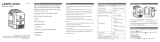
1 Exit opening for laser beam
2 Pulse-function indicator
3 Pulse-function button
4 Operating mode button
5 Battery indicator
6 Tripod mount 1/4" - 20
7 Battery compartment
8 Battery lid
9 Polarity leads
10 Latch of battery lid
11 Tripod mount 5/8" - 11
12 Product label
13 Serial number
14 On/Off switch
15 Guide groove
16 Guide rail
17 Locking screw for extendable stand
18 Fine adjustment knob
19 Rotating base
20 Magnets
21 Laser target plate
Product Features
1) The working range can be decreased by unfavorable environmental
conditions (e.g. direct sun irradiation).
* dust and splash proof
Please observe the serial number on the product label of your line laser
tool.
The laser tool can be clearly identified with the serial number 13 on the
product label.
The numbering of the product features shown refers to the illustration
of the laser tool on the graphic page.
BM 2610A16273 07-13_BM 2610A16273 07-13 7/30/13 2:02 PM Page 10

-11-
22 Construction tripod BS 150*
23 Laser viewing glasses*
24 Positioning device WM 1*
25 Telescoping pole system BP350*
26 Laser receiver LR 2*
27 L-Boxx 2*
* The accessories illustrated or described are not included as
standard delivery.
Preparation
Always turn off the laser and the main power switch before
removing and replacing batteries.
Alkaline batteries are recommended for the tool.
Always replace all batteries at the same time. Use only batteries
from one brand and with identical capacity.
Remove the batteries from tool when not using for extended
periods. When storing for extended periods, the batteries can corrode
and discharge themselves.
When inserting, pay attention to the correct polarity according to
the representation of the inside battery lid.
It is the user’s responsibility to periodically check the accuracy of
the laser tool as work progresses. Always check the accuracy of
the laser tool after it has been dropped or subject to extreme
temperature and temperature variations.
To open the battery lid 8, pull latch 10 and fold the battery lid out. Insert
the batteries. When inserting, pay attention to the correct polarity
according to the representation on the outside of the battery lid.
When the battery indication 5 flashes red, the batteries must be replaced.
Assembly
BM 2610A16273 07-13_BM 2610A16273 07-13 7/30/13 2:02 PM Page 11

-12-
Make sure the tool and device are securely mounted
before use.
Using the Rotating Mount
Place the laser tool with the guide groove 15 on
the guide rail 16 of the rotating mount 19 and
slide the laser tool to the stop onto the mount.
To disconnect, pull the laser tool in the opposite
direction from the rotating mount.
Extending the Telescopic Legs
Unscrew the locking screw 17 for the extendable
stand. Pull out the stand. Lock the stand by
tightening the locking screw 17. Repeat the
process for the other two stands.
Operation
Initial Operation
Switching On and Off
To switch on the tool, slide the On/Off switch 14 to the “ on” position
(when working without self leveling) or to the “ on” position (when
working with self leveling). Immediately after switching on, the laser tool
sends laser beams out of the exit openings 1.
Do not point the laser beam at persons or animals
and do not look into the laser beam yourself, not
even from a long distance.
To switch off the laser tool, slide the On/Off switch 14 to the “off” position.
When switching off, the leveling unit is locked.
!
WARNING
!
CAUTION
BM 2610A16273 07-13_BM 2610A16273 07-13 7/30/13 2:02 PM Page 12

-13-
When exceeding the maximum permitted operating temperature of 40 °C,
the laser tool switches off to protect the laser diode. After cooling down,
the laser tool is ready for operation and can be switched on again.
Deactivating the Automatic Shut-off
The laser tool switches off automatically after an operating duration of 30
minutes. To deactivate the automatic switch-off, keep the operating mode
button 4 pressed for 3 s while switching on the laser tool. When the
automatic switch-off is deactivated, the laser lines briefly flash after
3 s.
To activate the automatic shut-off, switch the laser tool off and then on
again (without the operating mode button 4 pushed).
Operation Modes (see figures A–D)
The laser tool has four operating modes, between which you can switch
at any time:
– Horizontal operation (operating mode A): generates a horizontal laser
line.
– Cross-line operation (operating mode B): generates a horizontal and a
vertical laser line.
– Vertical operation (operating mode C): generates two vertical, orthogonal
laser lines,
– Horizontal operation combined with vertical operation (operating mode
D): generates a horizontal and two vertical laser lines..
In all operating modes, a plumb down point is projected onto the floor.
Once switched on, the laser tool is in operating mode “D”. To change the
operating mode, press the operating mode button 4.
All four operating modes can be selected with or without self leveling.
In cross-line and vertical operation, the vertical lines can be aligned exactly
on a reference object using the fine adjustment knob 18.
Pulse Function
When working with the laser receiver 26, the pulse function must be
activated, – independent of the selected operating mode.
In pulse function, the laser lines flash at very high frequency (invisible to
the human eye) and thus becomes detectable by the laser receiver 26.
BM 2610A16273 07-13_BM 2610A16273 07-13 7/30/13 2:02 PM Page 13

-14-
To switch on the pulse function, press button 3. When the pulse function
is switched on, the pulse-function indicator 2 lights up green.
When the pulse function is switched on, the visibility of the laser lines is
reduced for the human eye. Therefore, turn off the pulse function by
pushing button 3 when working without the laser receiver. When the pulse
function is switched off, the pulse-function indicator 2 is deactivated.
Self Leveling
Working with Self Leveling
Position the laser tool on a level and firm support or mount it to a compact
tripod.
When working with self leveling, slide the On/Off switch 14 to the “ on”
position (this means pendulum is unlocked).
After switching on, the leveling function automatically compensates
irregularities within the self-leveling range of ±4°. The laser tool is leveled
in as soon as the laser lines no longer flash.
If the self leveling function is not possible, e.g. because the surface on
which the laser tool is mounted and slopes by more than 4° from the
horizontal plane, the laser beams flash. In this case, bring the laser tool to
the level position and allow the self-leveling to take place.
In case of ground vibrations or position changes during operation, the laser
tool is automatically levelled in again. To avoid errors, check the position
of the horizontal and vertical laser line with regard to the reference points
upon re-leveling.
Working without Self Leveling (manual mode)
For work without self leveling, slide the On/Off switch 14 to the “ on”
position. When the self leveling is switched off, the laser lines flash
continuously.
When the self leveling is switched off, the laser tool can be held by hand
or placed on an sloping surface. In cross-line operation, the two laser lines
do not necessarily run at a 90° to each other.
Leveling Accuracy
Influences on Accuracy
The ambient temperature has the greatest influence. Especially
temperature differences occurring from the ground up can divert the laser
beam.
BM 2610A16273 07-13_BM 2610A16273 07-13 7/30/13 2:02 PM Page 14

-15-
Because the largest difference in temperature layers is close to the ground,
the laser tool should always be mounted on a tripod when measuring
distances exceeding 65 ft. If possible, also set up the laser tool in the
middle of the work area.
Apart from exterior influences, device-specific influences (such as heavy
impact or falling) can lead to deviations. Therefore, check the accuracy of
the laser tool every time before starting your work.
First, check both the height as well as the leveling accuracy of the
horizontal laser line, then the leveling accuracy of the vertical laser line.
Should the laser tool exceed the maximum deviation during one of the
tests, please have it repaired by a Bosch after- sales service.
Checking the Height Accuracy of the Horizontal Line
For this check, a free measuring distance of 15 ft on a firm surface between
two walls A and B is required.
– Mount the laser tool onto a tripod or place it on a firm and level surface
close to wall A. Switch on the laser tool. Select cross-line operation with
self leveling.
– Direct the laser against the close wall A and allow the laser tool to level
in. Mark the centre of the point where the laser lines cross each other on
the wall (point I).
A
B
5 m
BM 2610A16273 07-13_BM 2610A16273 07-13 7/30/13 2:02 PM Page 15

-16-
– Turn the laser tool by 180°, allow it to level in and mark the cross point
of the laser lines on the opposite wall B (point II).
– Without turning the laser tool, position it close to wall B. Switch the laser
tool on and allow it to level in.
– Align the height of the laser tool (using a tripod or by underlaying, if
required) in such a manner that the cross point of the laser lines is
projected against the previously marked point II on the wall B.
A
B
A
B
180˚
d
180˚
A
B
BM 2610A16273 07-13_BM 2610A16273 07-13 7/30/13 2:02 PM Page 16

-17-
– Without changing the height, turn around the laser tool by 180°. Direct it
against the wall A in such a manner that the vertical laser line runs
through the already marked point I. Allow the laser tool to level in and
mark the cross point of the laser lines on the wall A (point III).
– The difference d of both marked points I and III on wall A indicates the
actual height deviation of the laser tool.
The maximum permitted deviation d
max
is calculated as follows:
d
max
= double distance of the walls x 0.3 mm/m
Example: With a 5 metre distance between the walls, the maximum
deviation must not exceed
d
max
= 2 x 5m x 0.3 mm/m = 3 mm. Thus, the marks must not be more than
3 mm apart.
Checking the Leveling Accuracy of the Horizontal Line
For the check, a free surface of approx. 5 x 5 metres is required.
– Set up the laser tool on a firm, level surface between both walls A and B.
Allow the laser tool to level in while in horizontal operation.
– At a distance of 2.5 metres from the laser tool, mark the centre of the
laser line (point I on wall A and point II on wall B) on both walls.
2,5 m
,0 m
5,
5
A
B
BM 2610A16273 07-13_BM 2610A16273 07-13 7/30/13 2:02 PM Page 17

-18-
– Set up the laser tool 5 metres away turned by 180° and allow it to level
in.
– Align the height of the laser tool (using a tripod or by underlaying, if
required) in such a manner that the centre of the laser line is projected
exactly against the previously marked point II on wall B.
– Mark the centre of the laser line as point III (vertically above or below
point I) on the wall A.
– The difference d of both marked points I and III on wall A indicates the
actual deviation of the laser tool from the level plane.
The maximum permitted deviation d
max
is calculated as follows:
d
max
= double distance of the walls x 0.3 mm/m
Example: With a 5 metre distance between the walls, the maximum
deviation must not exceed.
d
max
= 2x 5 m x 0.3mm/m=3mm. Thus, the marks must not be more than
3 mm apart.
Checking the Leveling Accuracy of the Vertical Line
For this check, a door opening is required with at least 2.5 m of space (on
a firm surface) to each side of the door.
d
2 m
A
B
BM 2610A16273 07-13_BM 2610A16273 07-13 7/30/13 2:02 PM Page 18

-19-
– Position the laser tool on a firm, level surface (not on a tripod) 2.5 m
away from the door opening. Allow the laser tool to level in while in
cross-line operation mode, and direct the laser beams at the door
opening.
– Mark the centre of the vertical laser line at the floor of the door opening
(point I), at a distance of 5 m beyond the other side of the door opening
(point II) and at the upper edge of the door opening (point III).
2,5 m
2,5 m
2 m
d
BM 2610A16273 07-13_BM 2610A16273 07-13 7/30/13 2:02 PM Page 19

-20-
– Position the laser tool on the other side of the door opening directly
behind point II. Allow the laser tool to level in and align the vertical laser
line in such a manner that its centre runs exactly through points I and II.
– The difference d between point III and the centre of the laser line at the
upper edge of the door opening results in the actual deviation of the laser
tool from the vertical plane.
– Measure the height of the door opening.
The maximum permitted deviation dmax is calculated as follows:
d
max
= double height of the door opening x 0.3mm/m
Example: With a door opening height of 2 metres, the maximum permitted
deviation is
d
max
= 2 x 2m x 0.3 mm/m = 1.2 mm. Thus, the marks must not be more
than 1.2 mm apart.
Checking plumb accuracy
For this check, a free measuring distance of approx. 5m between floor and
ceiling on a firm surface is required.
– Mount the laser tool onto the rotating platform and place it on the floor.
– Switch the laser tool on and allow it to level.
– Mark the centre of the upper crossing point on the ceiling (point I). Also
mark the centre of the bottom laser point on the floor (point II).
5 m
BM 2610A16273 07-13_BM 2610A16273 07-13 7/30/13 2:02 PM Page 20

-21-
– Rotate the laser tool 180°. Position it so that the centre of the lower laser
point is on the point II which has already been marked. Allow the laser
tool to level.
Mark the centre of the upper laser point (point III).
– The difference d of both marked points I and III on the ceiling results in
the actual deviation of the laser tool to the plumb line.
In the measuring distance of 5m the maximum permissible deviation is: 5
m x ±0.5mm/mx2= ±5mm.
The difference d between the points I and III can therefore be at most 5
mm.
180°
d
Working Advise
Always use the centre of the laser line for marking. The width of the
laser line changes with the distance.
Working with the Laser Target (Accessory) (see figures G–H)
With the laser target 21, it is possible to project the laser mark onto the
floor or the laser height onto a wall.
With the zero field and the scale, the offset or drop to the required height
can be measured and projected at another location. This eliminates the
necessity of precisely adjusting the laser tool to the height to be projected.
BM 2610A16273 07-13_BM 2610A16273 07-13 7/30/13 2:02 PM Page 21

-22-
The laser target 21 has a reflective coating that enhances the visibility of
the laser beam at greater distances or in intense sunlight. The brightness
intensification can be seen only when viewing, parallel to the laser beam,
onto the laser target.
Working with the Tripod (Accessory)
A tripod offers a stable, height-adjustable measuring support. Put the laser
tool onto the thread of the tripod 22 or of a commercially available
construction tripod using the 1/4" tripod mount 6. Tighten the laser tool
using the tripod’s locking screw.
Working with the Laser Receiver (Accessory) (see figure E)
Under unfavourable light conditions (bright environment) and for larger
distances, use the laser receiver for improved detection of the laser lines
26. When working with the laser receiver, switch the pulse function on (see
“Pulse Function”, page 12-14).
Laser Viewing Glasses (Accessory)
The laser viewing glasses filter out the ambient light. This makes the red
light of the laser appear brighter for the eyes.
Do not use the laser viewing glasses as safety goggles. The laser
viewing glasses are used for improved visualisation of the laser beam, but
they do not protect against laser radiation.
Do not use the laser viewing glasses as sun glasses or in traffic. The
laser viewing glasses do not afford complete UV protection and reduce
colour perception.
Work Examples
Work Examples (see figures A –F)
Applicational examples for the laser tool can be found on the graphics
pages.
BM 2610A16273 07-13_BM 2610A16273 07-13 7/30/13 2:02 PM Page 22

-23-
Store and transport the laser tool only in the supplied protective
case.
Keep the laser tool clean at all times.
Do not immerse the measuring tool into water or other fluids.
Wipe off debris using a moist and soft cloth. Do not use any cleaning
agents or solvents.
Store and transport the tool only in the belt pouch 29.
Keep the tool clean at all times.
Do not immerse the tool into water or other fluids.
Wipe off debris using a moist and soft cloth. Do not use any
cleaning agents or solvents.
Regularly clean the surfaces at the exit opening of the laser in
particular, and pay attention to any fluff of fibers.
If the tool should fail despite the care taken in manufacturing and
testing procedures, repair should be carried out by an authorized
after-sales service center for Bosch power tools.
In all correspondence and spare parts orders, please always
include the 10-digit article number given on the type plate of
the tool.
For repairs, only send in the tool in the belt pouch 29.
Environment protection
Recycle raw materials & batteries instead of disposing of waste. The unit,
accessories, packaging & used batteries should be sorted for
environmentally friendly recycling in accordance with the latest regulations.
Maintenance and Service
BM 2610A16273 07-13_BM 2610A16273 07-13 7/30/13 2:02 PM Page 23
Page is loading ...
Page is loading ...
Page is loading ...
Page is loading ...
Page is loading ...
Page is loading ...
Page is loading ...
Page is loading ...
Page is loading ...
Page is loading ...
Page is loading ...
Page is loading ...
Page is loading ...
Page is loading ...
Page is loading ...
Page is loading ...
Page is loading ...
Page is loading ...
Page is loading ...
Page is loading ...
Page is loading ...
Page is loading ...
Page is loading ...
Page is loading ...
Page is loading ...
Page is loading ...
Page is loading ...
Page is loading ...
Page is loading ...
Page is loading ...
Page is loading ...
Page is loading ...
Page is loading ...
Page is loading ...
Page is loading ...
Page is loading ...
Page is loading ...
Page is loading ...
Page is loading ...
Page is loading ...
Page is loading ...
Page is loading ...
Page is loading ...
Page is loading ...
Page is loading ...
-
 1
1
-
 2
2
-
 3
3
-
 4
4
-
 5
5
-
 6
6
-
 7
7
-
 8
8
-
 9
9
-
 10
10
-
 11
11
-
 12
12
-
 13
13
-
 14
14
-
 15
15
-
 16
16
-
 17
17
-
 18
18
-
 19
19
-
 20
20
-
 21
21
-
 22
22
-
 23
23
-
 24
24
-
 25
25
-
 26
26
-
 27
27
-
 28
28
-
 29
29
-
 30
30
-
 31
31
-
 32
32
-
 33
33
-
 34
34
-
 35
35
-
 36
36
-
 37
37
-
 38
38
-
 39
39
-
 40
40
-
 41
41
-
 42
42
-
 43
43
-
 44
44
-
 45
45
-
 46
46
-
 47
47
-
 48
48
-
 49
49
-
 50
50
-
 51
51
-
 52
52
-
 53
53
-
 54
54
-
 55
55
-
 56
56
-
 57
57
-
 58
58
-
 59
59
-
 60
60
-
 61
61
-
 62
62
-
 63
63
-
 64
64
-
 65
65
-
 66
66
-
 67
67
-
 68
68


Ask a question and I''ll find the answer in the document
Finding information in a document is now easier with AI
in other languages
- français: Bosch GLL 3-50 S Manuel utilisateur
- español: Bosch GLL 3-50 S Manual de usuario
Related papers
-
Bosch GLL 3-15 User manual
-
Bosch GLL 2-20 User guide
-
-
Bosch Power Tools GPL5 User manual
-
Bosch GTL2 User manual
-
-
-
-
-
Bosch Power Tools GPL 3 Professional User manual
Other documents
-
-
Bosch Appliances GLL2-50 User manual
-
Craftsman CMHT77630 Owner's manual
-
Craftsman CMHT77629 Owner's manual
-
Parkside PKLL 8 A1 Translation Of The Original Instructions
-
 Tavool T04 User manual
-
-
Hammerhead HLCL001 Owner's manual
-
 TOUGHBUILT TB-H2-LL-30-L2 User manual
-
Stabila LAR-250 User manual

