Samsung SPE-400B User manual
- Category
- Video servers/encoders
- Type
- User manual

4CH NETWORK
ENCODER
(BLADE TYPE)
User Manual
SPE-400B

Copyright
©2011 Samsung Techwin Co., Ltd. All rights reserved.
Trademark
is the registered logo of Samsung Techwin Co., Ltd.
The name of this product is the registered trademark of Samsung Techwin Co., Ltd.
Other trademarks mentioned in this manual are the registered trademark of their respective company.
Restriction
Samsung Techwin Co., Ltd shall reserve the copyright of this document. Under no circumstances, this
document shall be reproduced, distributed or changed, partially or wholly, without formal authorization of
Samsung Techwin.
Disclaimer
Samsung Techwin makes the best to verify the integrity and correctness of the contents in this document, but
no formal guarantee shall be provided. Use of this document and the subsequent results shall be entirely on
the user’s own responsibility. Samsung Techwin reserves the right to change the contents of this document
without prior notice.
Warranty
If the product does not operate properly in normal conditions, please let us know. Samsung Techwin will resolve
the problem for free of charge. The warranty period is 3 years. However, the followings are excluded:
If the system behaves abnormally because you run a program irrelevant to the system operation.
Deteriorated performance or natural worn-out in process of time
•
•
4Ch Network Encoder
(Blade Type)
User Manual

English _3
● OVERVIEW
IMPORTANT SAFETY INSTRUCTIONS
Read these instructions.
Keep these instructions.
Heed all warnings.
Follow all instructions.
Do not use this apparatus near water.
Clean only with dry cloth.
Do not block any ventilation openings, Install in accordance with the manufacturer’s
instructions.
Do not install near any heat sources such as radiators, heat registers, stoves, or other
apparatus (including amplifi ers) that produce heat.
Do not defeat the safety purpose of the polarized or grounding-type plug. A polarized
plug has two blades with one wider than the other. A grounding type plug has two
blades and a third grounding prong. The wide blade or the third prong are provided for
your safety, If the provided plug does not fi t into your outlet, consult an electrician for
replacement of the obsolete outlet.
Protect the power cord from being walked on or pinched particularly at plugs,
convenience receptacles, and the point where they exit from the apparatus.
Only use attachments/ accessories specifi ed by the manufacturer.
Use only with the cart, stand, tripod, bracket, or table specifi ed by
the manufacturer, or sold with the apparatus. When a cart is used,
use caution when moving the cart/apparatus combination to avoid
injury from tip-over.
Unplug this apparatus during lighting storms or when unused for
long periods of time.
Refer all servicing to qualifi ed service personnel. Servicing is required when the apparatus
has been damaged in any way, such as power-supply cord or plug is damaged, liquid has
been spilled or objects have fallen into the apparatus, the apparatus has been exposed to
rain or moisture, does not operate normally, or has been dropped.
1.
2.
3.
4.
5.
6.
7.
8.
9.
10.
11.
12.
13
.
14.
overview
overview
4_ overview
WARNING
TO REDUCE THE RISK OF FIRE OR ELECTRIC SHOCK, DO NOT EXPOSE
THIS PROCUCT TO RAIN OR MOISTURE. DO NOT INSERT ANY METALLIC
OBJECT THROUGH THE VENTILATION GRILLS OR OTHER OPENNINGS
ON THE EQUIPMENT.
Apparatus shall not be exposed to dripping or splashing and that no objects
filled with liquids, such as vases, shall be placed on the apparatus.
CAUTION
CAUTION
RISK OF ELECTRIC SHOCK.
DO NOT OPEN
CAUTION
: TO REDUCE THE RISK OF ELECTRIC SHOCK.
DO NOT REMOVE COVER (OR BACK).
NO USER SERVICEABLE PARTS INSIDE.
REFER SERVICING TO QUALIFIED SERVICE PERSONNEL.
EXPLANATION OF GRAPHICAL SYMBOLS
The lightning flash with arrowhead symbol, within an
equilateral triangle, is intended to alert the user to the
presence of “dangerous voltage” within the product’s
enclosure that may be of sufficient magnitude to constitute a
risk of electric shock to persons.
The exclamation point within an equilateral triangle is intended
to alert the user to the presence of important operating
and maintenance (servicing) instructions in the literature
accompanying the product.

English _5
● OVERVIEW
Class construction
An apparatus with CLASS construction shall be connected to a MAINS
socket outlet with a protective earthing connection.
Battery
Batteries(battery pack or batteries installed) shall not be exposed to excessive
heat such as sunshine, fire or the like.
It is essential that when changing the battery in the unit, the replacement
battery must be of the same type otherwise there may be a possibility of an
explosion.
CALIFORNIA USA ONLY
This Perchlorate warning applies only to primary CR (Manganese Dioxide)
Lithium coin cells in the product sold or distributed ONLY in California USA.
“Perchlorate Material - special handling may apply, See www.dtsc.ca.gov/
hazardouswaste/perchlorate.”
CAUTION
These servicing instructions are for use by qualified service personnel only.
To reduce the risk of electric shock do not perform any servicing other than
that contained in the operating instructions unless you are qualified to do so.
Please use the input power with just one Network Encoder and other devices
must not be connected.

overview
6_ overview
Please read the following recommend safety precautions carefully.
Do not Place this apparatus on an uneven surface.
Do not install on a surface where it is exposed to direct sunlight, near
heating equipment or heavy cold area.
Do not place this apparatus near conductive material.
Do not attempt to service this apparatus yourself.
Do not place a glass of water on the product.
Do not install near any magnetic sources.
Do not block any ventilation openings.
Do not place heavy items on the product.
User’s Manual is a guidance book how to use the products
The meaning of the using sign in the book is following
Reference : In case of providing information for helping of product’s usages
Notice : If there’s any possibility to occur any damages for the goods and
human caused by not following the instruction
Ú
Please read this manual for the safety before using of goods and keep it in
the safe place.
y
y
y
y
y
y
y
y
y
y

English _7
● OVERVIEW
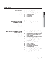
CONTENTS
OVERVIEW
3
3 Important Safety Instructions
9 Product Features
9 Recomended PC Specifi cations
10 What’s Included
11 At a Glance
14 Checking IP
INSTALLATION &
CONNECTION
15
15 Installation
16 Connecting with other Device
NETWORK CONNECTION
AND SETUP
19
19 Connecting the Network Encoder
Directly to Local Area Networking
20 Connecting the Network Encoder
Directly to a DHCP Based DSL/
Cable Modem
21 Connecting the Network Encoder
Directly to a PPPoE Modem
22 Connecting the Network Encoder
to a Broadband Router with the
PPPoE/Cable Modem
23 Buttons used in IP Installer
24 Static IP Setup
28 Dynamic IP Setup
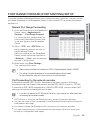
29 Port Range Forward (Port
Mapping) Setup
31 Connecting to the Network
Encoder from a Shared Local PC
31 Connecting to the Network
Encoder from a Remote PC via
the Internet

overview
8_ overview
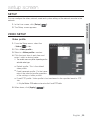
SETUP SCREEN
39
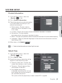
39 Setup
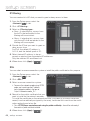
39 Video Setup
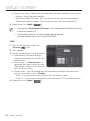
42 Network Setup
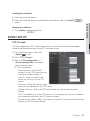
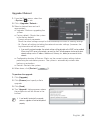
47 Event Setup
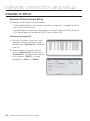
53 System Setup
APPENDIX
58
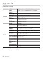
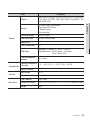
58 Specifi cation
60 Product Overview
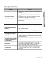
61 Troubleshooting
62 Open Source Announcement
64 GPL/LGPL Software License
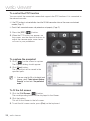
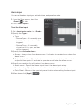
WEB VIEWER
32
32 Connecting to the Network
encoder
33 Login
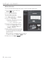
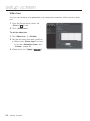
34 Installing Silverlight Runtime
36 Using the Live Screen
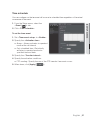
37 Using the Camera Menu

English _9
● OVERVIEW
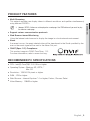
PRODUCT FEATURES
Multi-Streaming
This network encoder can display videos in different resolutions and qualities simultaneously
using different CODECs.
M
However, MPEG-4 video can not be played on a web page. Use CMS software if you want to play
the video on a web page.
Support various communication protocols
Web Browser-based Monitoring
Using the Internet web browser to display the image in a local network environment.
Alarm
If an event occurs, the event-related video will be transferred to the Email specifi ed by the
user or the event signal will be sent to the Alarm Out port.
ONVIF (Spec 1.01) Compliance
This product supports ONVIF Core Spec. 1.01.
For more information, refer to www.onvif.org.
RECOMENDED PC SPECIFICATIONS
CPU : Intel(R) Core(TM)2 2.00 GHz or higher
Operating System : Windows XP, VISTA, 7
Mac OS
Resolution : 1280X1024 pixels or higher
RAM : 1GB or higher
Web Browser :
Internet Explorer 7.0 or higher, Firefox, Chrome, Safari
Video Memory : 128MB or higher
y
y
y
y
y
y
y
y
y
y
y

overview
10_ overview
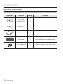
WHAT’S INCLUDED
Please check if your network encoder and accessories are all included in the product package.
Appearance Item Name Quantity Description
User Manual,
Installer S/W CD
1
CMS S/W DVD 1
Quick Guide 1
Terminal Block 1 Used for RS-485 or alarm cable connection.
ASSY-Tapping Screw
2 Used to fix Blade (SPE-400B) with the rack

English _11
● OVERVIEW
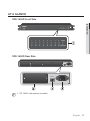
AT A GLANCE
SPE-1600R Front Side
SPE-1600R Rear Side
SPE-1600R is sold separately (unbundled).
M
108&3
/&5803,
108&3
/&5803,
&5)&3/&5
"$
_*/
&5)&3/&5
"$
_*/

overview
12_ overview
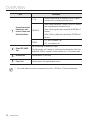
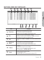
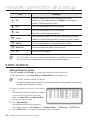
Item Description
Network connection
indicator for each
channel, Power and
Network Indicator
1~16
Channels connected to the network will blink the green
indicator with the network connection status.
NETWORK
When network connection is made, it blinks in a different
color according to the connection status.
Green : Blinks in green when connected to
1000 Base-T
Ethernet.
Yellow :
Blinks in yellow when connected to 10/100 Base-T
Ethernet.
POWER
ON : While the power is on.
OFF : If the power is off.
b
Blade (SPE-400B)
Slot
Slot for mounting the Blade (SPE-400B).
The slot numbers are 1 through 4, starting from the leftmost one. When the
Blade (SPE-400B) is installed, it will be assigned an IP in the numeric order.
c
Network Port Used to connect a LAN cable.
Power Port Used to connect the specified power source.
For smooth video transmission, recommend to install in 1000 Base-T Ethernet environment.
M

English _13
● OVERVIEW
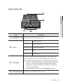
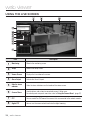
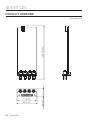
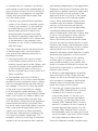
Blade (SPE-400B)
Item Description
VIDEO IN (CH 1~CH 4)
Used to connect the BNC video input signal.
b
I/O Port
D+ (1~4) RS-485 Data Line
D- (1~4) RS-485 Data Line
ALARM IN (1~4) Alarm Input (sensor) Port
G GND
ALARM OUT (1~4)
Alarm Out Port
c
Reset Button
Resets the network encoder settings to the default. Press and hold it for
about 5 seconds to turn off the system indicator and restart the system.
J
If you reset the network encoder, the network settings will be adjusted
so that DHCP can be enabled. If there is no DHCP server in the network,
you must run the IP Installer program to change the basic network
settings such as IP address, Subnet mask, Gateway, etc., before you
can connect to the network.
For more information on IP settings, refer to “Network Setup”. (page 42)
Rack Connector Port Used to connect Blade (SPE-400B) to the rack.
7*%&0*/ 7*%&0*/ 7*%&0*/ 7*%&0*/
%%%%%%%%
(
34
"-"3.
*/
"-"3.
065
3&4&5

overview
14_ overview
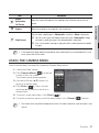
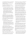
CHECKING IP
By factory default, the IP of each Blade (SPE-400B) is set to “192.168.1.100~103”.
If you use IP INSTALLER to check the IPs after inserting all 4 Blades (SPE-400B), you may
encounter a redundant IP.
If this is the case, use IP INSTALLER to change the IP manually, or press and hold the <RESET>
button on the rear panel for 5 seconds to correct the IP assignment in a numeric order.
Slot No. Initial IP IP after <RESET>
192.168.1.100~103 192.168.1.100~103
b
192.168.1.100~103 192.168.1.104~107
c
192.168.1.100~103 192.168.1.108~111
192.168.1.100~103 192.168.1.112~115
&5)&3/&5
"$
_*/
7*%&0*/ 7*%&0*/ 7*%&0*/ 7*%&0*/
%%%%%%%%
(
34
"-"3.
*/
"-"3.
065
3&4&5
7*%&0*/ 7*%&0*/ 7*%&0*/ 7*%&0*/
%%%%%%%%
(
34
"-"3.
*/
"-"3.
065
3&4&5
7*%&0*/ 7*%&0*/ 7*%&0*/ 7*%&0*/
%%%%%%%%
(
34
"-"3.
*/
"-"3.
065
3&4&5
7*%&0*/ 7*%&0*/ 7*%&0*/ 7*%&0*/
%%%%%%%%
(
34
"-"3.
*/
"-"3.
065
3&4&5
English _15
● INSTALLATION & CONNECTION
installation & connection
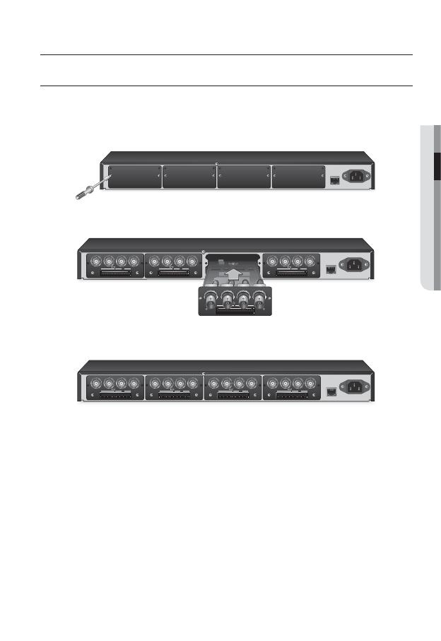
INSTALLATION
To install Blade (SPE-400B)
Loosen the screws on either side of the cover in the Blade (SPE-400B) compartment
for SPE-1600R.
Fit Blade (SPE-400B) into both sliding lines as shown and insert it in the arrow
direction.
Insert the Blade (SPE-400B) until it fi ts into the connector of the rack, and tighten
the screws.
1.
2.
3.
&5)&3/&5
"$
_*/
&5)&3/&5
"$
_*/
7*%&0*/ 7*%&0*/ 7*%&0*/ 7*%&0*/
%%%%%%%%
(
34
"-"3.
*/
"-"3.
065
3&4&5
7*%&0*/ 7*%&0*/ 7*%&0*/ 7*%&0*/
%%%%%%%%
(
34
"-"3.
*/
"-"3.
065
3&4&5
7*%&0*/ 7*%&0*/ 7*%&0*/ 7*%&0*/
%%%%%%%%
(
34
"-"3.
*/
"-"3.
065
3&4&5
7*%&0*/ 7*%&0*/ 7*%&0*/ 7*%&0*/
%%%%%%%%
(
34
"-"3.
*/
"-"3.
065
3&4&5
&5)&3/&5
"$
_*/
7*%&0*/ 7*%&0*/ 7*%&0*/ 7*%&0*/
%%%%%%%%
(
34
"-"3.
*/
"-"3.
065
3&4&5
7*%&0*/ 7*%&0*/ 7*%&0*/ 7*%&0*/
%%%%%%%%
(
34
"-"3.
*/
"-"3.
065
3&4&5
7*%&0*/ 7*%&0*/ 7*%&0*/ 7*%&0*/
%%%%%%%%
(
34
"-"3.
*/
"-"3.
065
3&4&5
7*%&0*/ 7*%&0*/ 7*%&0*/ 7*%&0*/
%%%%%%%%
(
34
"-"3.
*/
"-"3.
065
3&4&5
installation & connection
16_ installation & connection
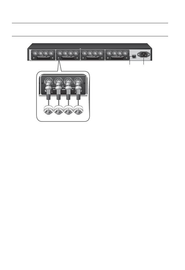
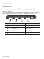
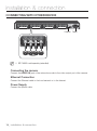
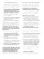
CONNECTING WITH OTHER DEVICE
SPE-1600R is sold separately (unbundled).
Connecting the camera
Connect the [VIDEO IN] port of the network encoder to the video output port of the camera.
Ethernet Connection
Connect the Ethernet cable to the local network or to the Internet.
Power Supply
Connect the power cable.
M
&5)&3/&5
"$
_*/
7*%&0*/ 7*%&0*/ 7*%&0*/ 7*%&0*/
%%%%%%%%
(
34
"-"3.
*/
"-"3.
065
3&4&5
7*%&0*/ 7*%&0*/ 7*%&0*/ 7*%&0*/
%%%%%%%%
(
34
"-"3.
*/
"-"3.
065
3&4&5
7*%&0*/ 7*%&0*/ 7*%&0*/ 7*%&0*/
%%%%%%%%
(
34
"-"3.
*/
"-"3.
065
3&4&5
7*%&0*/ 7*%&0*/ 7*%&0*/ 7*%&0*/
%%%%%%%%
(
34
"-"3.
*/
"-"3.
065
3&4&5
Ethernet Power
7*%&0*/ 7*%&0*/ 7*%&0*/ 7*%&0*/
%%%%%%%%
(
34
"-"3.
*/
"-"3.
065
3&4&5
Camera
English _17
● INSTALLATION & CONNECTION
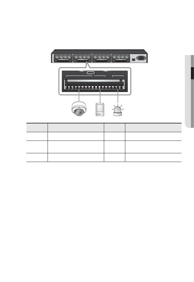
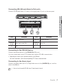
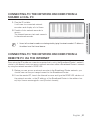
Connecting RS-485 and Alarm In/Out ports
Connect RS-485 and Alarm I/O cables to the appropriate I/O ports on the rear panel.
Port Description Port Description
D+(1~4) RS-485 Data Line D-(1~4) RS-485 Data Line
ALARM IN
(1~4)
Alarm Input (sensor) Port
ALARM OUT
(1~4)
Alarm Out
G GND
Connecting to the RS-485 device
Connect the external device to the [RS-485 D+, D-] ports.
You can connect and control PTZ camera that supports RS-485 communication.
Depending on camera’s type, connection polarity can be different.
For further information, refer to the corresponding PTZ Camera’s documentation.
Connecting to the Alarm Input
Connect one signal cable (out of 2) of applicable sensor to the [ALARM IN] port, and the
other to the [G] port.
You must use the specifi c RS-485 alarm I/O ports for each channel.
M
&5)&3/&5
"$
_*/
7*%&0*/ 7*%&0*/ 7*%&0*/ 7*%&0*/
%%%%%%%%
(
34
"-"3.
*/
"-"3.
065
3&4&5
7*%&0*/ 7*%&0*/ 7*%&0*/ 7*%&0*/
%%%%%%%%
(
34
"-"3.
*/
"-"3.
065
3&4&5
7*%&0*/ 7*%&0*/ 7*%&0*/ 7*%&0*/
%%%%%%%%
(
34
"-"3.
*/
"-"3.
065
3&4&5
7*%&0*/ 7*%&0*/ 7*%&0*/ 7*%&0*/
%%%%%%%%
(
34
"-"3.
*/
"-"3.
065
3&4&5
%%%%%%%%
(
34
"-"3.
*/
"-"3.
065
3&4&5

installation & connection
18_ installation & connection
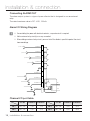
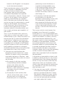
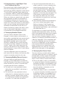
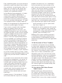
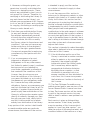
Connecting ALARM OUT
The alarm output system is a type of open collector that is designed to use an external
relay.
The rated maximum value is DC +24V, 100mA.
Alarm I/O Wiring Diagram
For controlling the power with electrical contacts, a separate circuit is required.
Add an external relay circuit(s) as many as needed.
When adding an external relay circuit, you must install the diodes in parallel to protect the circuit
from overvoltage.
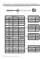
Channel I/O port table
RS-485 ALARM IN
ALARM OUT
RS-485 ALARM IN
ALARM OUT
CH 1 D1+, D1- 1, G 1, G CH 3 D3+, D3- 3, G 3, G
CH 2 D2+, D2- 2, G 2, G CH 4 D4+, D4- 4, G 4, G
J
10
11
12
13
14
9
15
16
17
ALARM IN 1
ALARM IN 2
ALARM IN 3
ALARM IN 4
GND
ALARM OUT 1
ALARM OUT 2
ALARM OUT 3
ALARM OUT 4
(12mA sink)
(12mA sink)
(12mA sink)
(12mA sink)
DC
5V
NO
NC
CM
<external relay circuit>
English _19
●
NETWORK CONNECTION AND SETUP
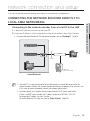
You can set up the network settings according to your network configurations.
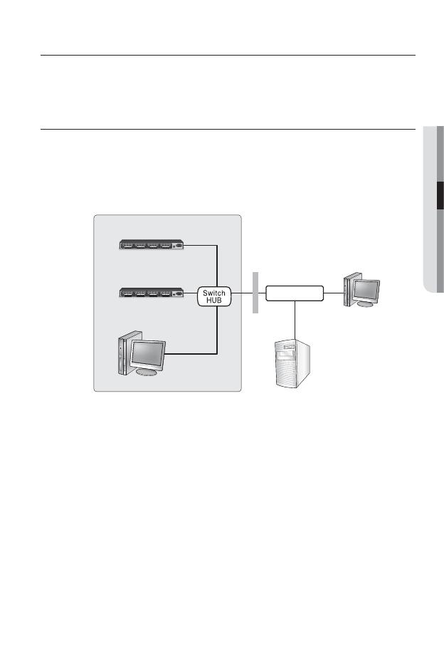
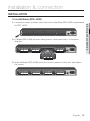
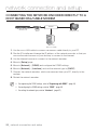
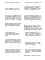
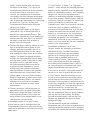
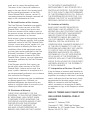
CONNECTING THE NETWORK ENCODER DIRECTLY TO
LOCAL AREA NETWORKING
Connecting to the network encoder from a local PC in the LAN
Launch an Internet browser on the local PC.
Enter the IP address of the network encoder in the address bar of the browser.
For information about the default IP of the network encoder, refer to “Checking IP”. (Page14)
A remote PC in an external Internet out of the LAN network may not be able to connect to the
network encoder installed in the intranet if the port-forwarding is not properly set or a fi rewall is set.
In this case, to resolve the problem, contact your network administrator.
By factory default, the IP address will be assigned from the DHCP server automatically.
If there is no DHCP server available, the IP address will be set to 192.168.1.100~103.
To change the IP address, use the IP Installer.
For further details on IP Installer use, refer to “Static IP Setup”. (Page 24)
1.
2.
M
network connection and setup
&5)&3/&5
"$
_*/
7*%&0*/ 7*%&0*/ 7*%&0*/ 7*%&0*/
%%%%%%%%
(
34
"-"3.
*/
"-"3.
065
3&4&5
7*%&0*/ 7*%&0*/ 7*%&0*/ 7*%&0*/
%%%%%%%%
(
34
"-"3.
*/
"-"3.
065
3&4&5
7*%&0*/ 7*%&0*/ 7*%&0*/ 7*%&0*/
%%%%%%%%
(
34
"-"3.
*/
"-"3.
065
3&4&5
7*%&0*/ 7*%&0*/ 7*%&0*/ 7*%&0*/
%%%%%%%%
(
34
"-"3.
*/
"-"3.
065
3&4&5
&5)&3/&5
"$
_*/
7*%&0*/ 7*%&0*/ 7*%&0*/ 7*%&0*/
%%%%%%%%
(
34
"-"3.
*/
"-"3.
065
3&4&5
7*%&0*/ 7*%&0*/ 7*%&0*/ 7*%&0*/
%%%%%%%%
(
34
"-"3.
*/
"-"3.
065
3&4&5
7*%&0*/ 7*%&0*/ 7*%&0*/ 7*%&0*/
%%%%%%%%
(
34
"-"3.
*/
"-"3.
065
3&4&5
7*%&0*/ 7*%&0*/ 7*%&0*/ 7*%&0*/
%%%%%%%%
(
34
"-"3.
*/
"-"3.
065
3&4&5
Network Encoder
Local PC
Firewall
External Remote PC
DDNS Server
(Data Center, KOREA)
INTERNET
<Local Network>
Network Encoder
20_ network connection and setup
network connection and setup
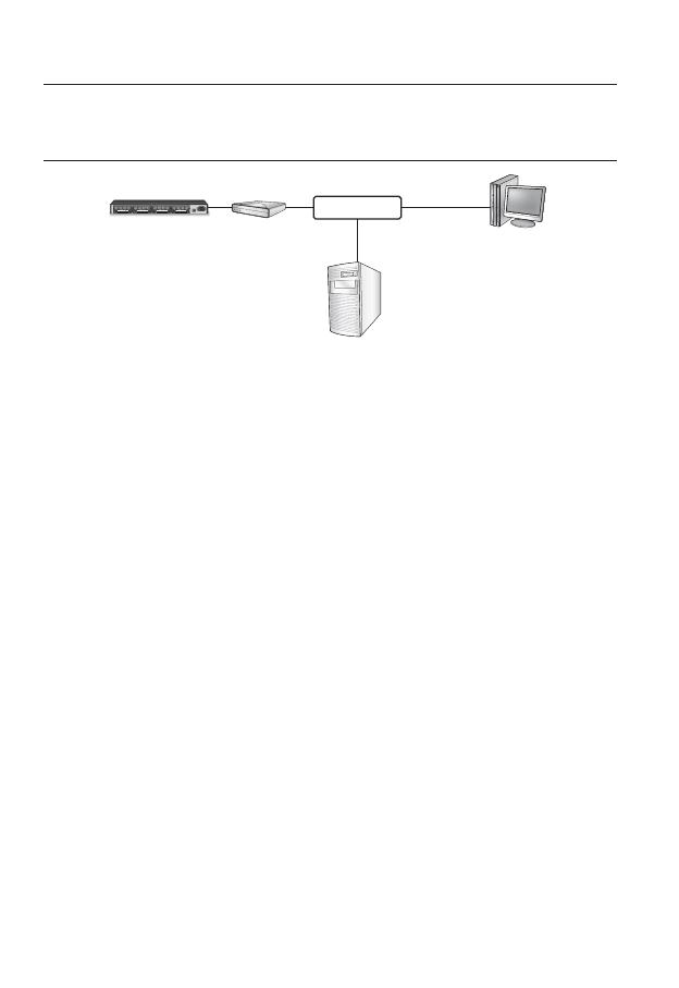
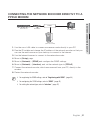
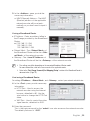
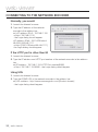
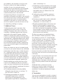
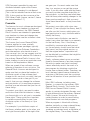
CONNECTING THE NETWORK ENCODER DIRECTLY TO A
DHCP BASED DSL/CABLE MODEM
Use the cross LAN cable to connect the network cable directly to your PC.
Run the IP Installer and change the IP address of the network encoder so that you
can use the web browser on your desktop to connect to the Internet.
Use the Internet browser to connect to the network encoder.
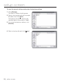
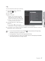
Move to [Setup] page.
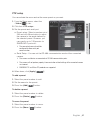
Move to [Network] – [DDNS] and confi gure the DDNS settings.
Move to [Network] – [Interface], and set the network type to [DHCP].
Connect the network encoder, which was removed from your PC, directly to the
modem.
Restart the network encoder.
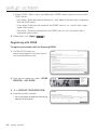
For registering the DDNS settings, refer to “Registering with DDNS”. (page
44)
For confi guring the DDNS settings, refer to “DDNS”. (page
43)
For setting the network type, refer to “Interface”. (page
42)
1.
2.
3.
4.
5.
6.
7.
8.
M
&5)&3/&5
"$
_*/
7*%&0*/ 7*%&0*/ 7*%&0*/ 7*%&0*/
%%%%%%%%
(
34
"-"3.
*/
"-"3.
065
3&4&5
7*%&0*/ 7*%&0*/ 7*%&0*/ 7*%&0*/
%%%%%%%%
(
34
"-"3.
*/
"-"3.
065
3&4&5
7*%&0*/ 7*%&0*/ 7*%&0*/ 7*%&0*/
%%%%%%%%
(
34
"-"3.
*/
"-"3.
065
3&4&5
7*%&0*/ 7*%&0*/ 7*%&0*/ 7*%&0*/
%%%%%%%%
(
34
"-"3.
*/
"-"3.
065
3&4&5
Network Encoder
External Remote PC
DDNS Server
(Data Center, KOREA)
DSL/Cable
Modem
INTERNET
Page is loading ...
Page is loading ...
Page is loading ...
Page is loading ...
Page is loading ...
Page is loading ...
Page is loading ...
Page is loading ...
Page is loading ...
Page is loading ...
Page is loading ...
Page is loading ...
Page is loading ...
Page is loading ...
Page is loading ...
Page is loading ...
Page is loading ...
Page is loading ...
Page is loading ...
Page is loading ...
Page is loading ...
Page is loading ...
Page is loading ...
Page is loading ...
Page is loading ...
Page is loading ...
Page is loading ...
Page is loading ...
Page is loading ...
Page is loading ...
Page is loading ...
Page is loading ...
Page is loading ...
Page is loading ...
Page is loading ...
Page is loading ...
Page is loading ...
Page is loading ...
Page is loading ...
Page is loading ...
Page is loading ...
Page is loading ...
Page is loading ...
Page is loading ...
Page is loading ...
Page is loading ...
Page is loading ...
Page is loading ...
Page is loading ...
Page is loading ...
Page is loading ...
Page is loading ...
Page is loading ...
Page is loading ...
Page is loading ...
Page is loading ...
Page is loading ...
Page is loading ...
Page is loading ...
Page is loading ...
Page is loading ...
Page is loading ...
Page is loading ...
Page is loading ...
Page is loading ...
Page is loading ...
Page is loading ...
Page is loading ...
-
 1
1
-
 2
2
-
 3
3
-
 4
4
-
 5
5
-
 6
6
-
 7
7
-
 8
8
-
 9
9
-
 10
10
-
 11
11
-
 12
12
-
 13
13
-
 14
14
-
 15
15
-
 16
16
-
 17
17
-
 18
18
-
 19
19
-
 20
20
-
 21
21
-
 22
22
-
 23
23
-
 24
24
-
 25
25
-
 26
26
-
 27
27
-
 28
28
-
 29
29
-
 30
30
-
 31
31
-
 32
32
-
 33
33
-
 34
34
-
 35
35
-
 36
36
-
 37
37
-
 38
38
-
 39
39
-
 40
40
-
 41
41
-
 42
42
-
 43
43
-
 44
44
-
 45
45
-
 46
46
-
 47
47
-
 48
48
-
 49
49
-
 50
50
-
 51
51
-
 52
52
-
 53
53
-
 54
54
-
 55
55
-
 56
56
-
 57
57
-
 58
58
-
 59
59
-
 60
60
-
 61
61
-
 62
62
-
 63
63
-
 64
64
-
 65
65
-
 66
66
-
 67
67
-
 68
68
-
 69
69
-
 70
70
-
 71
71
-
 72
72
-
 73
73
-
 74
74
-
 75
75
-
 76
76
-
 77
77
-
 78
78
-
 79
79
-
 80
80
-
 81
81
-
 82
82
-
 83
83
-
 84
84
-
 85
85
-
 86
86
-
 87
87
-
 88
88


Samsung SPE-400B User manual
- Category
- Video servers/encoders
- Type
- User manual
Ask a question and I''ll find the answer in the document
Finding information in a document is now easier with AI
Related papers
Other documents
-
tekmar 485 Installation guide
-
D-Link AC2600 MU-MIMO Wi-Fi Gigabit Router DIR-882 User manual
-
 TBS TBS2603SE NDI Quick Start
-
Toshiba IK-WD01A/3.3-12 User manual
-
Proteus PRO Quick start guide
-
Optimus IXW-MA User manual
-
SoundCraft 400B Series User manual
-
 TBS TBS2603AU Quick Start
-
Sanyo VCC-HD2300P User manual
-
For Dummies 978-0-470-52465-7 Datasheet

