
Installation and Operation Manual
X-VA-1307-eng
Part Number: 541B079AHG
March, 2008
Model 1307
5
Model 1307 O-ring Seal Flowmeter
Model 1307
Installation and Operation Manual
X-VA-1307-eng
Part Number: 541B079AHG
March, 2008
Model 1307
Essential Instructions
Read this page before proceeding!
Brooks Instrument designs, manufactures and tests its products to meet many national and international standards. Because
these instruments are sophisticated technical products, you must properly install, use and maintain them to ensure they
continue to operate within their normal specifications. The following instructions must be adhered to and integrated into your
safety program when installing, using and maintaining Brooks Products.
• Read all instructions prior to installing, operating and servicing the product. If this instruction manual is not the correct
manual, please see back cover for local sales office contact information. Save this instruction manual for future reference.
• If you do not understand any of the instructions, contact your Brooks Instrument representative for clarification.
• Follow all warnings, cautions and instructions marked on and supplied with the product.
• Inform and educate your personnel in the proper installation, operation and maintenance of the product.
• Install your equipment as specified in the installation instructions of the appropriate instruction manual and per applicable
local and national codes. Connect all products to the proper electrical and pressure sources.
• To ensure proper performance, use qualified personnel to install, operate, update, program and maintain the product.
• When replacement parts are required, ensure that qualified people use replacement parts specified by Brooks Instrument.
Unauthorized parts and procedures can affect the product's performance and place the safe operation of your process at
risk. Look-alike substitutions may result in fire, electrical hazards or improper operation.
• Ensure that all equipment doors are closed and protective covers are in place, except when maintenance is being
performed by qualified persons, to prevent electrical shock and personal injury.
Pressure Equipment Directive (PED)
All pressure equipment with an internal pressure greater than 0.5 bar (g) and a size larger than 25mm or 1" (inch) falls under the
Pressure Equipment Directive (PED). The Directive is applicable within the European Economic Area (EU plus Norway, Iceland
and Liechtenstein). Pressure equipment can be traded freely within this area once the PED has been complied with.
• Section 1 of this manual contains important safety and operating instructions related to the PED directive.
• Meters described in this manual are in compliance with EN directive 97/23/EC module H Conformity Assessment.
• All Brooks Instrument Flowmeters fall under fluid group 1.
• Meters larger than 25mm or 1" (inch) are in compliance with category I, II, III of PED.
• Meters of 25mm or 1" (inch) or smaller are Sound Engineering Practice (SEP).
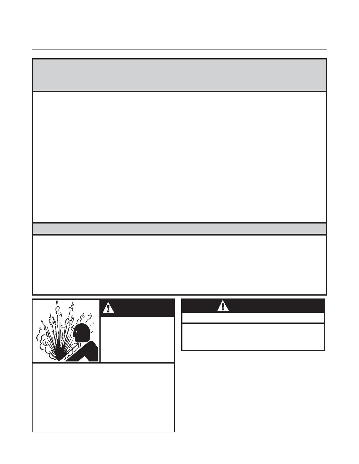
GLASS TUBE
EXPLOSION
HAZARD
WARNING
Plastic protective sleeve must remain over glass
tube.
Fasten meter windows securely.
Do not operate above pressure and temperature
limits.
Avoid pressure and flow surges.
Do not service or repair while pressurized.
Read and understand instruction manual.
Failure to comply could result in serious personal
injury or property damage.
Protectivesleeve
must
remain
over
glass
tube.
Fasten meter windows securely.
Failure to comply could result in serious personal
injury or property damage.
WARNING
GLASS TUBE EXPLOSION HAZARD

Installation and Operation Manual
X-VA-1307-eng
Part Number: 541B079AHG
March, 2008
Model 1307
Dear Customer,
We appreciate this opportunity to service your flow measurement and control requirements with a Brooks
Instrument device. Every day, flow customers all over the world turn to Brooks Instrument for solutions to their
gas and liquid low-flow applications. Brooks provides an array of flow measurement and control products for
various industries from biopharmaceuticals, oil and gas, fuel cell research and chemicals, to medical devices,
analytical instrumentation, semiconductor manufacturing, and more.
The Brooks product you have just received is of the highest quality available, offering superior performance,
reliability and value to the user. It is designed with the ever changing process conditions, accuracy requirements
and hostile process environments in mind to provide you with a lifetime of dependable service.
We recommend that you read this manual in its entirety. Should you require any additional information concerning
Brooks products and services, please contact your local Brooks Sales and Service Office listed on the back cover
of this manual or visit www.BrooksInstrument.com
Yours sincerely,
Brooks Instrument

Installation and Operation Manual
X-VA-1307-eng
Part Number: 541B079AHG
March, 2008
Model 1307
THIS PAGE WAS
INTENTIONALLY
LEFT BLANK

i
Contents
Contents
Section 1
Introduction
Page
Description...................................................................................1-1
Design Features ..........................................................................1-1
Specifications ..............................................................................1-1
Optional Equipment .....................................................................1-2
Section 2
Installation
Receipt of Equipment ..................................................................2-1
Recommended Storage Practice.................................................2-1
Installation ...................................................................................2-1
Section 3
Operation
Operating Instructions .................................................................3-1
Section 4
Maintenance
General........................................................................................4-1
Figures
1-1 Float Types....................................................................1-4
1-2 Dimensions ...................................................................1-4
2-1 Typical Bypass Installation ............................................2-2
2-2 Panel Cutouts................................................................2-3
3-1 Reading Edge of Floats.................................................3-2
3-2 Typical Bypass Installation ............................................3-2
Tables
1-1 Capacities .....................................................................1-3
1-2 Pressure Ratings ..........................................................1-3
C
O
N
T
E
N
T
S

ii
Brooks Instrument Model 1307 O-ring Seal Flowmeter

1-1
Introduction
Introduction
1-1 Description
Model 1307 O-ring seal flowmeters are economical, accurate indicating
flowmeters. They are designed for applications where the industrial
features or special materials of construction of Brooks
®
standard Full-
View
®
or GT 1000 flowmeters are not required.
1-2 Design Features
• Side-plate construction
• Ten-to-one rangeability
• O-ring seal - inlet and outlet same size
• Choice of float types and capacity ranges
• Standard NPT connections
1-3 Specifications
WARNING
Do not operate this instrument in excess of the specifications listed
below. Failure to heed this warning can result in serious personal
injury and/or damage to the equipment.
WARNING
Glass metering tubes are designed for operation up to the maximum
operating pressures and temperatures as specified herein. Due to
the inherent brittle characteristics of glass and conditions beyond
our control, tube breakage could result even within specified
operating conditions. Do not use glass tube meters with fluids that
are toxic, or chemically react with glass such as water above 140°F,
steam, alkalis, flourine, hydrofluoric acid, or molten metal. Failure
to heed warning can result in serious personal injury and/or damage
to the equipment.
Capacities
Refer to Table 1-1
Flow Accuracy
Standard: ±2% full scale from 100% down to 10% of scale reading.
Optional: ±1% of full scale from 100% down to 10% of scale reading.
Repeatability
0.5% full scale
Pressure Ratings
Refer to Table 1-2
Section
1

Brooks Instrument Model 1307 O-ring Seal Flowmeter
1-2
Scales
Length: 250 mm
Standard: Fused on metering tube, choice of arbitrary millimeter or
calibration data sheet; percentage of maximum flow with factor tag.
Optional: Direct reading, engraved detachable metal plate.
Ambient Temperature Limits
33°F to 125°F (1°C to 52°C)
Operating Fluid Temperature Limits
33°F to 250°F (1°C to 121°C)
Materials of Construction:
Metering Tube
Borosilicate Glass
Protective Tube Sleeve
UV stabilized polycarbonate
GLASS TUBE
EXPLOSION
HAZARD
WARNING
Plastic protective sleeve must remain over glass
tube.
Fasten meter windows securely.
Do not operate above pressure and temperature
limits.
Avoid pressure and flow surges.
Do not service or repair while pressurized.
Read and understand instruction manual.
Failure to comply could result in serious personal
injury or property damage.
Floats
Size 7 (1/2") (ball floats) glass, 316 stainless steel, Monel
®
Size 8 (1/2") - 13 (1/2") 316 stainless steel
Float Stops
316 stainless steel
Float Types
Spherical: Size 7 meter only
Types RV, LJ and RS: Sizes 8 to 13, refer to Figure 1-1
Housing
Side-plates: Aluminum, stainless steel
End Fittings
Brass or 316 stainless steel

1-3
Introduction
O-rings
Standard: Buna-N
Optional: Viton-A
®
fluoroelastomers
Window
Scratch resistant, UV stabilized polycarbonate
Protectivesleeve
must
remain
over
glass
tube.
Fasten meter windows securely.
Failure to comply could result in serious personal
injury or property damage.
WARNING
GLASS TUBE EXPLOSION HAZARD
Connections
NPT female
Dimensions
Refer to Figure 1-2
1-4 Optional Equipment
Mounting - front of panel screws
Table 1-1. Capacities.
WATER AIR @ 14.7 PSIA AND 70°F (21°C)
METER PRESSURE DROP VISCOSITY IMMUNITY PRESSURE DROP PSI
SIZE TUBE FLOAT GPM LPM INCHES W.C. CEILING, CS (**) SCFM SLPM INCHES W.C. CRITICAL (*)
GLASS 0.17 0.64 1.0 1.0 0.93 26.3 2.0 0
7 R-7M-25-1F STN. STL. 0.37 1.40 3.0 1.0 1.64 46.4 4.0 0
MONEL 0.39 1.48 4.0 1.0 1.72 48.7 4.0 0
8-RV-3 0.78 2.95 4.0 2.0 3.17 89.8 4.0 0
8-RV-8 1.09 4.13 7.0 3.7 4.45 126.0 8.0 0
8-RS-8 1.40 5.30 10.0 1.8 5.86 166.0 11.0 0
8 R-8M-25-4F 8-RV-14 1.45 5.49 12.0 5.4 5.88 166.5 14.0 0
8-RS-14 1.83 6.93 17.0 1.9 7.56 214.1 19.0 0
8-RV-31 2.06 7.80 23.0 7.0 8.32 235.6 28.0 30
8-RS-31 2.59 9.80 33.0 3.1 10.66 301.9 37.0 30
9-RV-33 2.53 9.58 6.0 11.0 10.45 295.9 7.0 0
9 R-9M-25-3F 9-RS-33 3.24 12.26 7.0 2.4 13.45 380.9 8.0 0
9-RV-87 3.92 14.84 14.0 17.0 16.25 460.2 16.0 30
9-RS-87 5.12 19.38 17.0 3.5 21.20 600.4 20.0 30
10-RV-64 6.28 23.77 11.0 15.0 25.76 729.5 13.0 0
10 R-10M-25-3F 10-RS-64 7.84 29.67 15.0 3.7 32.15 910.5 17.0 0
10-RV-138 8.84 33.46 23.0 23.0 36.10 1022.4 26.0 30
10-RS-138 10.93 41.37 29.0 5.5 45.90 1299.9 33.0 30
12-RV-221 17.21 65.14 10.0 29.0 70.80 2005.1 11.0 0
12-RV-343 20.95 79.30 15.0 36.0 86.45 2448.3 17.0 30
12 R-12M-25-5F 12-RS-221 22.40 84.78 12.0 4.2 91.85 2601.2 14.0 0
12-RS-343 26.90 101.82 18.0 4.5 112.00 3171.8 20.0 30
12-LJ-740 67.60 255.87 65.0 1.0 299.50 8481.8 75.0 30
13-RV-510 31.78 120.29 17.0 42.0 130.90 3707.1 19.0 0
13-RV-760 37.60 142.32 24.0 52.0 155.20 4395.3 27.0 30
13 R-13M-25-3F 13-RS-510 42.52 160.94 23.0 7.6 176.60 5001.3 26.0 0
13-RS-760 49.55 187.55 32.0 9.3 217.70 6165.3 36.0 30
13-LJ-1394 92.00 348.22 92.0 1.0
(*) MINIMUM OPERATING DOWNSTREAM PRESSURE FOR GAS SERVICE (PSIG)
(**) VISCOSITY IMMUNITY CEILING LISTED IS FOR STAINLESS STEEL FLOAT AND FLUID SP.GR. 1.0.

Brooks Instrument Model 1307 O-ring Seal Flowmeter
1-4
Table 1-2. Pressure Ratings.
Meter Maximum Working Max.
Size Pressure (psig) Temp.
Gas
Service
7 350
8 300
9 175 250°F
10 100 (121°C)
12 75
13 100
1. Pressure ratings are based on static pressure applicable at
250°F.
2. Glass tubes are not usable for caustic service.
3. Fluid temperatures below 32°F will cause frosting of the glass
metering tube. Please consult factory for applications below
this temperature.
Figure 1-1. Float Types.
READ
HERE
Spherical -
Lowest meter capacity and
no viscous fluids with medium
capacity.
Type LJ -
Maximum flowmeter capacity
with limited viscosity
immunity.
READ
HERE
Type RV (rib guided) -
Highest immunity to viscous
fluids with medium meter
capacity. (Most stable)
Type GV (rod guided) -
Analogous in design to a
sharp edge orifice. Gives
most immunity to viscosity
variations of the fluid being
metered.
READ
HERE
Type RV
(Rib guided)
Type RS (rib guided) - High
flow capacity with some
immunity to viscous fluids.
Type GS (rod guided) -
Analogous in design to a flow
nozzle or venturi. Offers the
maximum flow capacity in any
given size flowmeter.
READ
HERE
Type RS
(Rib guided)
Type LJSpherical

1-5
Introduction
Meter Dimensions
Size A B C D
7 & 8 16-15/16" 1/2" 2-3/8" 2-1/2"
9 16-15/16" 3/4" 2-3/8" 2-1/2"
10 17" 1" 2-3/8" 2-9/16"
12 19-1/16" 1-1/2" 3-3/8" 2-1/2"
13 21-7/16" 1-1/2" 4-1/2" 4-1/2"
Figure 1-2. Dimensions.

Brooks Instrument Model 1307 O-ring Seal Flowmeter
1-6

2-1
Installation
Installation
2-1 Receipt of Equipment
When the equipment is received, the outside of the packing case should
be checked for any damage incurred during shipment. If the packing case
is damaged, the local carrier should be notified at once regarding his
liability. Remove the envelope containing the shipping list. Carefully
remove the equipment from the packing case and inspect for any
damaged or missing parts.
In the event that the meter is damaged during shipment, the Product
Service Department, Brooks Instrument, LLC, Hatfield, PA 19440 should
be contacted to obtain a return shipment form.
2-2 Recommended Storage Practice
If intermediate or long term storage is required for equipment, as supplied
by Brooks Instrument, it is recommended that said equipment be stored in
accordance with the following:
a. Within the original shipping container.
b. Stored in a sheltered area, preferably a warm, dry heated warehouse.
c. Ambient temperature 70°F (21.0°C) nominal 110°F maximum/45°F
minimum (43°C maximum/7.1°C minimum).
d. Relative humidity 45% nominal 60% maximum/25% minimum.
Upon removal from storage, a visual inspection should be conducted to
verify the condition of equipment is "as received".
2-3 Installation
Prior to meter installation remove the plastic shipping tube
preventing float movement during shipping.
NOTICE
A. Location
For proper operation the Model 1307 must be mounted within 6 degrees of
true vertical, with the inlet connection at the bottom and the outlet at the
top. The use of a level is recommended to assure vertical positioning.
Piping must be adequately supported to prevent undue strain on the
flowmeter.
B. Piping Arrangement
It is recommended that bypass piping be installed around the flowmeter so
it may be isolated from the process line for servicing and cleaning. Refer to
Figure 2-1 for a typical installation.
Section
2

Brooks Instrument Model 1307 O-ring Seal Flowmeter
2-2
Figure 2-1. Typical Bypass
Installation.
A - Inlet Valve B - Outlet Valve C - Bypass Valv
e
D - Control Valve E - Drain Valve
HORIZONTAL
LINE
DA
E
C
VERTICAL
LINE
B
B
A
E
FLOWMETER
C
D
FLOWMETER
Do not allow the float to fall out of the metering tube. A damaged
float will affect the accuracy of the meter. Be careful not to break the
tube by pulling on it at an extreme angle or applying excessive force.
CAUTION
Failure to drain the flowmeter when isolated in a bypass loop may
result in tube breakage caused by thermal expansion of the process
liquid.
CAUTION
Horizontal outlet connection is provided on Model 1307 flowmeters
supplied with an alarm. For those flowmeters supplied with an alarm, the
outlet end fitting may be rotated in 90° increments.

3-1
Operation
Operation
3-1 Operating Instructions
After the flowmeter has been properly installed in the system, it is ready for
operation.
GLASS TUBE
EXPLOSION
HAZARD
WARNING
Plastic protective sleeve must remain over glass
tube.
Fasten meter windows securely.
Do not operate above pressure and temperature
limits.
Avoid pressure and flow surges.
Do not service or repair while pressurized.
Read and understand instruction manual.
Failure to comply could result in serious personal
injury or property damage.
Protectivesleeve
must
remain
over
glass
tube.
Fasten meter windows securely.
Failure to comply could result in serious personal
injury or property damage.
WARNING
GLASS TUBE EXPLOSION HAZARD
To initiate flow through a flowmeter using bypass piping, refer to Figure 3-1.
1. Close flowmeter isolation valves (A) and (B).
2. Fully open bypass valve (C) and slightly open control valve (D).
3. Initiate process flow. When flow has stabilized, fully open isolation valve
(B), then slowly open isolation valve (A) fully.
4. Close bypass valve (C).
5. Regulate process flow using control valve (D).
6. If meter is left in by pass configuration, open drain valve (E) to prevent
tube damage caused by thermal expansion of the process liquid.
Failure to drain the flowmeter when isolated in a bypass loop may
result in tube breakage caused by thermal expansion of the process
liquid.
CAUTION
Rate of flow is indicated by reading the increments inscribed on the
metering tube or direct etched scale parallel with the metering edge of the
float. For the correct reading edge of the float, refer to Figure 3-2.
Section
3

Brooks Instrument Model 1307 O-ring Seal Flowmeter
3-2
A - Inlet Valve B - Outlet Valve C - Bypass Valv
e
D - Control Valve E - Drain Valve
HORIZONTAL
LINE
DA
E
C
VERTICAL
LINE
B
B
A
E
FLOWMETER
C
D
FLOWMETER
Figure 3-1. Typical Bypass
Installation.
Figure 3-2. Reading edge of floats.
R
EAD
H
ERE
RV
RS
FLOW
BALL

4-1
Maintenance
Maintenance
4-1 General
Model 1307 flowmeters require little maintenance except routine cleaning.
It is necessary to remove the flowmeter from the line for tube and float
cleaning. The tube and float may be cleaned with a soft absorbent swab.
To disassemble the flowmeter proceed as follows:
a. Remove the front and rear window shields.
b. Remove four (4) screws connecting the bottom end fitting to the side
plate.
c. Carefully pull the end fitting and tube away from the side plates and top
fitting. DO NOT cock the tube when removing it from the top fitting.
d. Remove the polycarbonate sleeve surrounding the flow tube.
e. Remove the float from the tube.
Do not allow the float to fall out of the metering tube. A damaged
float will affect the accuracy of the meter. Be careful not to break the
tube by pulling on it at an extreme angle or applying excessive force.
CAUTION
f. Using a suitable solvent, carefully swab and flush the inside of the
metering tube. Clean the float and blow dry all parts thoroughly.
Anytime the meter is removed for service, new O-rings should be
installed in both the inlet and outlet end fittings.
NOTICE
Reassemble the flowmeter as follows:
a. Carefully install the float in the tube with the metering edge up. Refer to
Figure 3-1 to determine the metering edge location.
b. Carefully hold the tube, (with float installed), sleeve, and end fitting, and
push the tube on the top fitting.
c. Tighten the four (4) side plate screws in place.
d. Install the front and rear windows.
WARNING
Pressure test the meter before returning it to service. Hydrostatic
pressure testing should be performed by qualified personnel or
serious injury and/or damage to the equipment can result.
Section
4

Installation and Operation Manual
X-VA-1307-eng
Part Number: 541B079AHG
March, 2008
Model 1307
LIMITED WARRANTY
Seller warrants that the Goods manufactured by Seller will be free from defects in materials or workmanship under normal use
and service and that the Software will execute the programming instructions provided by Seller until the expiration of the
earlier of twelve (12) months from the date of initial installation or eighteen (18) months from the date of shipment by Seller.
Products purchased by Seller from a third party for resale to Buyer (“Resale Products”) shall carry only the warranty extended
by the original manufacturer.
All replacements or repairs necessitated by inadequate preventive maintenance, or by normal wear and usage, or by fault of
Buyer, or by unsuitable power sources or by attack or deterioration under unsuitable environmental conditions, or by abuse,
accident, alteration, misuse, improper installation, modification, repair, storage or handling, or any other cause not the fault of
Seller are not covered by this limited warranty, and shall be at Buyer’s expense.
Goods repaired and parts replaced during the warranty period shall be in warranty for the remainder of the original warranty
period or ninety (90) days, whichever is longer. This limited warranty is the only warranty made by Seller and can be
amended only in a writing signed by an authorized representative of Seller.
BROOKS LOCAL AND WORLDWIDE SUPPORT
Brooks Instrument provides sales and service facilities around the world, ensuring quick delivery from local stock, timely
repairs and local based sales and service facilities.
Our dedicated flow experts provide consultation and support, assuring successful applications of the Brooks flow
measurement and control products.
Calibration facilities are available in local sales and service offices. The primary standard calibration equipment to calibrate
our flow products is certified by our local Weights and Measures Authorities and traceable to the relevant international
standards.
START-UP SERVICE AND IN-SITU CALIBRATION
Brooks Instrument can provide start-up service prior to operation when required.
For some process applications, where ISO-9001 Quality Certification is important, it is mandatory to verify and/or (re)calibrate
the products periodically. In many cases this service can be provided under in-situ conditions, and the results will be traceable
to the relevant international quality standards.
CUSTOMER SEMINARS AND TRAINING
Brooks Instrument can provide customer seminars and dedicated training to engineers, end users and maintenance persons.
Please contact your nearest sales representative for more details.
HELP DESK
In case you need technical assistance:
Americas
1-888-554-FLOW
Europe +(31)-0318-549-290 Within Netherlands 0318-549-290
Asia
+011-81-3-5633-7100
Due to Brooks Instrument's commitment to continuous improvement of our products, all specifications are subject to change
without notice.
TRADEMARKS
Brooks ................................................................. Brooks Instrument, LLC
Full-View.............................................................. Brooks Instrument, LLC
Monel ............................................................Inco Alloys International Inc.
Viton...................................................... DuPont Performance Elastomers
-
 1
1
-
 2
2
-
 3
3
-
 4
4
-
 5
5
-
 6
6
-
 7
7
-
 8
8
-
 9
9
-
 10
10
-
 11
11
-
 12
12
-
 13
13
-
 14
14
-
 15
15
-
 16
16
-
 17
17
-
 18
18


Ask a question and I''ll find the answer in the document
Finding information in a document is now easier with AI
Related papers
-
 Brooks Glass Tube Full-View 1110 Operating instructions
-
 Brooks GT1600 Operating instructions
-
 Brooks 1358 Operating instructions
-
 Brooks Ar-Mite MT3750 Installation & Operation Manual
-
 Brooks 3809G / 3809G ELF / 3809G TFE Lined / 3810G User manual
-
 Brooks 3809G / 3809G ELF / 3809G TFE Lined / 3810G Operating instructions
-
 Brooks 3750C Operating instructions
-
 Brooks 5860i Operating instructions
-
 Brooks 5860E Operating instructions
-
 Brooks 5861E Operating instructions


Other documents
-
Omega FLD3000 Series Owner's manual
-
King 7460 Series Installation Instructions Manual
-
 Precision Medical 1MFA Oxygen Chrome Flowmeter User manual
-
Dwyer Series STFLO User manual
-
-
Rosemount 340 Trace Moisture Analyzer-Rev N Owner's manual
-
-
-
 Precision Medical 7MFA2001 Dial Flowmeter User manual
-

