Honeywell D365PL Installation guide

Category
Fire protection
Type
Installation guide

Honeywell D365PL is an air duct smoke detector designed to sense smoke in air handling systems. It utilizes photoelectric technology for efficient detection and provides remote alarm output for auxiliary devices like LED annunciators. With its sampling tube installation, the detector can be mounted in either a rectangular side-by-side configuration or a square top-over-bottom configuration, accommodating duct widths from 6 inches to 12 feet. Additionally, the detector features LED indicators for local visible indication and is compatible with various accessories like remote test stations.

Honeywell D365PL is an air duct smoke detector designed to sense smoke in air handling systems. It utilizes photoelectric technology for efficient detection and provides remote alarm output for auxiliary devices like LED annunciators. With its sampling tube installation, the detector can be mounted in either a rectangular side-by-side configuration or a square top-over-bottom configuration, accommodating duct widths from 6 inches to 12 feet. Additionally, the detector features LED indicators for local visible indication and is compatible with various accessories like remote test stations.

[2] GENERAL DESCRIPTION
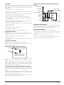
Smoke introduced into this air duct system will be distributed throughout the
entire building. Smoke detectors designed for use in air duct systems are used
to sense the presence of smoke in the duct.
Model D365PL Air Duct Smoke Detector uses photoelectric technology for the
detection of smoke. This detection method, when combined with an efficient
housing design, samples air passing through the duct and allows detection of
a developing hazardous condition. When sufficient smoke is sensed, an alarm
signal is initiated at the fire control panel monitoring the detector, and appro-
priate action can be taken to shut off fans, blowers, change over air handling
systems, etc. These actions can facilitate the management of toxic smoke and
fire gases throughout the areas served by the duct system.
The D365PL incorporates a sensor cover tamper feature that provides a trou-
ble signal at the panel immediately if the cover is removed or improperly in-
stalled. Proper installation of the sensor cover removes the trouble condition.
When programmed with the system control panel, two LEDs on each duct
smoke detector light to provide local visible indication.
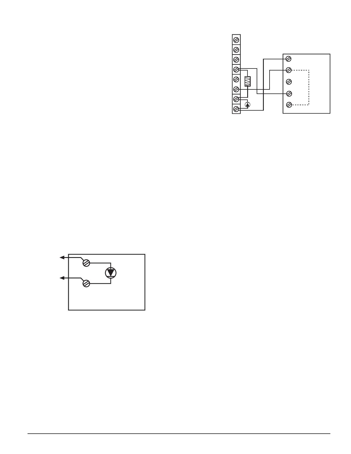
The D365PL provides a remote alarm output for use with auxiliary devices,
such as the RA100Z remote LED annunciator, as well as remote test capability
with the RTS151 or RTS151KEY Remote Test Stations.
[2.1] DETECTOR FEATURE SET
– Uses plug-in head SD365R (replaceable, see Section 11.1)
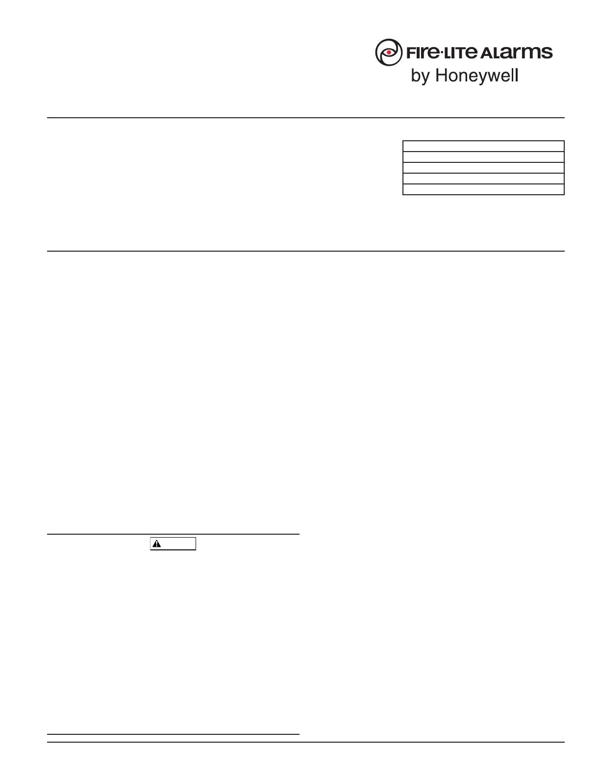
– Sampling tubes install from front and rear
– Compatible with existing accessories
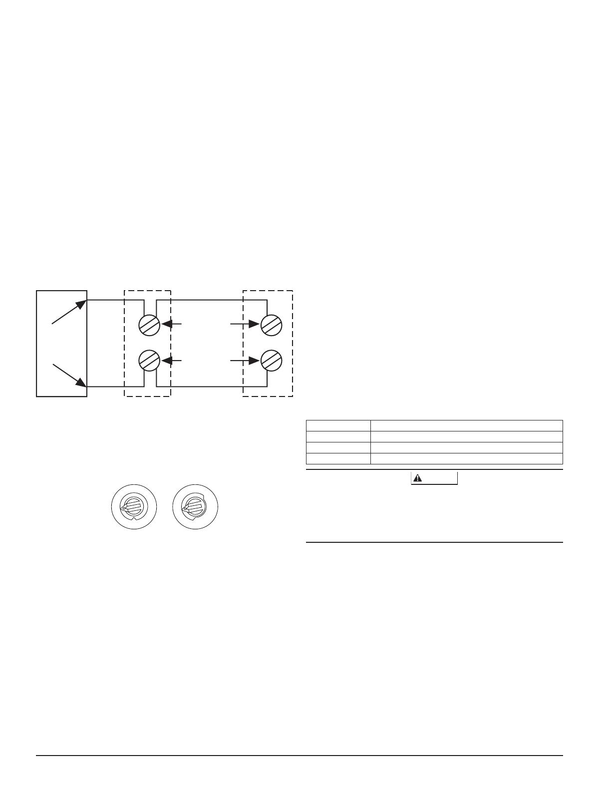
– Able to address detector per code switches on sensor head
[3] CONTENTS OF THE DUCT SMOKE DETECTOR KIT
1. Sensor/power board assembly and covers (with factory-installed sensor
head)
2. Three #10 sheet metal screws for mounting
3. Drilling template
4. One sampling tube end cap
5. One plastic exhaust tube
NOTE: A sampling tube must be ordered to complete the installation. It must
be the correct length for the width of the duct where it will be installed.
See Table 1 on page 2 to determine the inlet tube required for different duct
widths.
SPECIFICATIONS
Specifications
Operating Temperature: –4° to 158°F (–20° to 70°C)
32° to 120°F (0° to 49°C) with module installed in the D365PL
Storage Temperature: –22° to 158°F (–30° to 70°C)
Humidity: 0% to 93% Relative Humidity Non-condensing
Air Velocity: 100 to 4000 ft./min. (0.5 to 20.3 m/sec.)
Rectangular Footprint Dimensions: 14.38 in L×5 in W×2.5 in D (37 cm L×12.7 cm W×6.36 cm D)
Square Footprint Dimensions: 7.75 in L×9 in W×2.5 in D (19.7 cm L×22.9 cm W×6.35 cm D)
Weight: 1.8 pounds; 0.82 kg
Operating Voltage Range: 15 to 32 VDC
Standby Current: 200 µA @ 24 VDC (one communication every 5 seconds with LED blink enabled)
Max. Alarm Current (LED on): 6.2 mA @ 24 VDC
NOTE: The D365PL comes with the sensor head factory installed, part number SD365R-IV.
TABLE OF CONTENTS PAGE
[1] Limitations of Duct Smoke Detectors ................................................ 1
[2] General Description ......................................................................... 1
[3] Contents of the Duct Smoke Detector Kit .......................................... 1
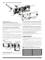
[4] Detector Installation ....................................................................... 2
[5] Sampling Tube Installation ............................................................... 2
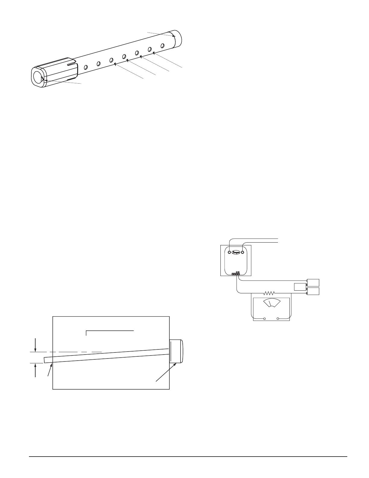
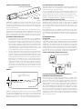
[6] Measurement Tests .......................................................................... 3
[7] Field Wiring; Installation Guidelines ................................................. 4
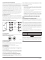
[8] Verification of Operation ................................................................. 4
[9] Cleaning ......................................................................................... 5
[10] Sensor Replacement ....................................................................... 5
[11] Optional Accessories ..................................................................... 5
BEFORE INSTALLING
Read System Sensor's Applications Guide: Duct Smoke Detectors (HVAG53),
which provides detailed information on detector spacing, placement, zoning,
wiring, and special applications. Copies of this manual are available online
at www.systemsensor.com. NFPA Standards 72 and 90A should also be refer-
enced for detailed information.
NOTICE: This manual shall be left with the owner/user of this equipment.
IMPORTANT: This detector must be tested and maintained regularly following
NFPA 72 requirements. The detector must be tested an maintained regularly
following NFPA 72 requirements. According to NFPA, the detector should be
visually inspected semiannually and functionally tested at least once a year.
This may need to be more frequent depending on the air quality of the duct
supply air.
[1] LIMITATIONS OF DUCT SMOKE DETECTORS
WARNING
The National Fire Protection Association has established that DUCT DETEC-
TORS MUST NOT BE USED AS A SUBSTITUTE FOR OPEN AREA DETECTOR
PROTECTION as a means of providing life safety. Nor are they a substitute for
early warning in a building’s regular fire detection system.
Fire-Lite supports this position and strongly recommends that the user read
NFPA Standards 90A, 72, and 101. The D365PL Air Duct Smoke Detectors are
listed per UL 268A.
This device will not operate without electrical power. Fire situations may
cause an interruption of power. The system safeguards should be discussed
with your local fire protection specialist.
This device will not sense smoke unless the ventilation system is operating
and the cover is installed.
For this detector to function properly, it MUST be installed according to the in-
structions in this manual. Furthermore, the detector MUST be operated within
ALL electrical and environmental specifications listed in this manual and the
sensor head installation manual. Failure to comply with these requirements
may prevent the detector from activating when smoke is present in the air
duct.
I56-6626-000
INSTALLATION AND MAINTENANCE INSTRUCTIONS
D365PL
Duct Smoke Detector
One FireLite Place
Northford, CT 06472
Phone: 203.484.7161
ACCESSORY CURRENT LOADS AT 24 VDC
DEVICE STANDBY ALARM
RA100Z 0mA 12mA Max.
RTS151 0mA 12mA Max.
RTS151KEY 12mA 12mA Max.
1 I56-6626-000
2/26/2019
[4] DETECTOR INSTALLATION
[4.1] VERIFY DUCT AIR FLOW DIRECTION AND VELOCITY
Model D365PL detectors are designed to be used in air handling systems hav-
ing air velocities of 100 to 4000 feet per minute. Duct widths from 6 inches to
12 feet can be accommodated. Be sure to check engineering specifications to
ensure that the air velocity in the duct falls within these parameters. If neces-
sary, use a velocity meter (anemometer) to check the air velocity in the duct.
[4.2] DETERMINE MOUNTING LOCATION AND CONFIGURATION
On ducts wider than 18 inches it is recommended that the detector be
mounted downstream of a bend, obstruction in the duct, or the supply or
return air inlet.
Exception: Installation of duct detectors can be on or within a commercial
packaged rooftop heating and air-conditioning system, fire/smoke dampers
and economizers. They may be mounted in either the supply and/or return air
section as determined by local code.
Once a suitable location is selected, determine if the detector is to be mounted
in a side-by-side “rectangular” configuration or a top-over-bottom “square”
configuration as shown in Figure 2. If mounting in the square configuration,
remove the rear attachment screw, rotate the unit at hinge, and replace the
screw into the new attachment hole as shown in Figure 2. Do NOT remove
the hinge screw during this process. Final installation approval shall be based
upon passing differential pressure and smoke entry tests described in Section
6 Measurement Tests.
FIGURE 2.
REMOVE SCREW AND PIVOT
DETECTOR AS SHOWN BELOW.
REPLACE SCREW
TO SECURE DETECTOR
IN PLACE.
H0550-00
[4.3] DRILL THE MOUNTING HOLES
Remove the paper backing from the mounting template supplied. Affix the
template to the duct at the desired mounting location. Make sure the template
lies flat and smooth on the duct.
[4.3.1] FOR RECTANGULAR SIDE-BY-SIDE MOUNTING CONFIGURATION
Center punch at four target centers: two “A” for sampling tubes and two “B”
for the rectangular configuration mounting tabs as shown on mounting tem-
plate. Drill pilot holes at target “A” centers and cut two 1.375 inch diameter
holes using a 138-inch hole saw or punch. Drill .156 inch diameter holes using
a 532 inch drill at target “B” centers.
[4.3.2] FOR SQUARE TOP-OVER-BOTTOM MOUNTING CONFIGURATION
Center punch at four target centers: two “A” for sampling tubes and two “C”
for the square configuration mounting tabs as shown on mounting template.
Drill pilot holes at target “A” centers and cut two 1.375 inch diameter holes
using a 138-inch hole saw or punch. Drill .156 inch diameter holes using a 532
inch drill at target “C” centers. If desired, drill an additional .156 inch hole at
the location of one of the mounting tabs on the lower housing.
[4.4] SECURE THE DUCT DETECTOR TO THE DUCT
Use two (rectangular configuration) or three (square configuration) of the pro-
vided sheet metal screws to screw the duct detector to the duct.
CAUTION: Do not overtighten the screws.
[5] SAMPLING TUBE INSTALLATION
[5.1] SAMPLING TUBE SELECTION
The sampling tube must be purchased separately. Order the correct length,
as specified in Table 1, for width of the duct where it will be installed. The
sampling tube length must extend across at least 5/8 of the width of the duct
for optimal performance.
The sampling tube is always installed with the air inlet holes facing into the
air flow. To assist proper installation, the tube’s connector is marked with an
arrow. Make sure the sampling tube is mounted so that the arrow points into
the airflow as shown in Figure 3. Mounting the detector housing in a vertical
orientation is acceptable provided that the air flows directly into the sam-
pling tube holes as indicated in Figure 3. The sampling tube and exhaust tube
can be mounted in either housing connection as long as the exhaust tube is
mounted downstream from the sampling tube.
TABLE 1. SAMPLING TUBES RECOMMENDED FOR DIFFERENT DUCT
WIDTHS
Outside Duct Width Sampling Tube Recommended*
Up to 1 ft. DST1
1 to 2 ft. DST1.5
2 to 4 ft. DST3
4 to 8 ft. DST5
8 to 12 ft. DST10 (2-piece)
*Must extend a minimum of 5/8 the duct width
FIGURE 1. EXPLODED VIEW OF DUCT SMOKE DETECTOR COMPONENTS
WIRING
COMPARTMENT
SAMPLING
TUBE
SOLD
SEPARATELY
EXHAUST TUBE
SENSOR MODULE
SENSOR HEAD
WIRING
COMPARTMENT
COVER
SENSOR
MODULE
COVER H0569-20
2 I56-6626-000
2/26/2019
FIGURE 3. AIR DUCT DETECTOR SAMPLING TUBE
SAMPLING TUBE ENDCAP
ARROW MUST FACE
INTO AIR FLOW
AIR FLOW
DIRECTION
H0551-00
CAUTION: The sampling tube end cap, included with the detector, is criti-
cal to proper operation of the duct smoke detector. The end cap is needed to
create the proper air flow to the sensor of the duct smoke detector. Once any
sampling tube length adjustments are made, plug the end of the sampling tube
with the provided end cap.
A plastic exhaust tube is included with the unit to be installed into the hous-
ing connection that is downstream from the sampling tube connection. The
exhaust tube can be installed from the front of the detector or the back. A
longer 1 foot exhaust tube, model ETX, is available as an accessory in cases
where the molded exhaust tube does not extend at least 2 inches into the duct.
[5.2] SAMPLING TUBE INSTALLATION
1. For tubes shorter than the width of the duct, slide the sampling tube,
with installed end cap, into the housing connection that meets the air-
flow first. Position the tube so that the arrow points into the airflow as
shown in Figure 3. Per NFPA sampling tubes over 3 feet long should be
supported at the end opposite of the duct detector. In ducts wider than 8
feet, work must be performed inside the duct to couple the other section
of the sampling tube to the section already installed using the ½-inch
conduit fitting supplied. Make sure that the holes on both sections of the
air inlet sampling tube are lined up and facing into the airflow.
2. For tubes longer than the width of the air duct, the tube should extend
out of the opposite side of the duct. Drill a ¾-inch hole in the duct op-
posite the hole already cut for the sampling tube. Ensure that the sam-
pling tube is angled downward from the duct smoke detector to allow for
moisture drainage away from the detector. The sampling tube should be
angled at least ¼˝ downward for every 12˝ of duct width per Figure 4.
There should be 10 to 12 holes spaced as evenly as possible across the
width of the duct. If there are more than 2 holes in the section of the tube
extending out of the duct, select a shorter tube using Table 1. Otherwise,
trim the tube to leave approximately 1 to 2 inches extending outside the
duct. Plug the end with the end cap and tape closed any holes in the
protruding section of the tube. Be sure to seal the duct where the tube
protrudes.
FIGURE 4.
DETECTOR
3/4˝
HOLE
12˝
1/4˝
H0215-00
NOTE: Air currents inside the duct may cause excessive vibration, especially
when the longer sampling tubes are used. In these cases, a 3-inch floor flange
(available at most plumbing supply stores) may be used to fasten the sam-
pling tube to the other side of the duct. When using the flange/connector
mounting technique, drill a 1 to 1¼-inch hole where the flange will be used.
[5.3] MODIFICATIONS OF SAMPLING TUBES
There may be applications where duct widths are not what is specified for the
installation. In such cases, it is permissible to modify a sampling tube that is
longer than necessary to span the duct width.
Use a 0.193-inch diameter (#10) drill and add the appropriate number of holes
so that the total number of holes exposed to the air flow in the duct is 10 to 12.
Space the additional holes as evenly as possible over the length of the tube.
CAUTION: This procedure should only be used as a temporary fix. It is not
intended as a permanent substitute for ordering the correct length tubes.
[5.4] REMOTE SAMPLING TUBE INSTALLATION
The detector arrangement can also incorporate the remote mounting of the
sampling tube and/or exhaust tube. In this case both the detector, sampling
tube and exhaust tube (if included) should be rigidly mounted to withstand
the pressure and vibrations caused by the air velocity. The location of the
detector’s sampling tube should be such that there is uniform airflow in the
cross section area.
Pressure differential across the sampling and exhaust ports in the detector
housing shall be verified to be between 0.01 and 1.11 inches of water. Do so
by measuring the pressure difference between the inlet and outlet ports on the
detector housing using a manometer as described in Section 6 Measurement
Tests.
[6] MEASUREMENT TESTS
[6.1] AIR FLOW
The D365PL is designed to operate over an extended air speed range of 100
to 4000 FPM. To verify sufficient sampling of ducted air, turn the air handler
on and use a manometer to measure the differential pressure between the two
sampling tubes. The differential pressure should measure at least 0.01 inches
of water and no more than 1.11 inches of water. Because most commercially
available manometers cannot accurately measure very low pressure differen-
tials, applications with less than 500 FPM of duct air speed may require one
of the following: 1) the use of a current-sourcing pressure transmitter (Dwyer
Series 607) or 2) the use of aerosol smoke, see below for test descriptions.
FIGURE 5. PROCEDURE FOR VERIFYING AIR FLOW
HIGH LOW
9 VOLT
BATTERY
9 VOLT
BATTERY
9 VOLT
BATTERY
TO SAMPLING TUBE
TO EXHAUST TUBE
DIFFERENTIAL
PRESSURE
TRANSMITTER
MODEL #607-01
15 TO 36
VDC SUPPLY
1000 OHM 5%
1 WATT RESISTOR
VOLT METER FLUKE
MODEL 87 OR
EQUIVALENT
+– H0163-01
[6.2] LOW FLOW AIR FLOW TEST USING DWYER SERIES 607
DIFFERENTIAL PRESSURE TRANSMITTER
Verify the air speed of the duct using an anemometer. Air speed must be
at least 100 FPM. Wire the Dwyer transmitter as shown in Figure 5. Con-
nect the leads of the meter to either side of the 1000Ω resistor. Allow unit to
warm up for 15 seconds. With both HIGH and LOW pressure ports open to
ambient air, measure and record the voltage drop across the 1000Ω resistor
(measurement 1), 4.00 volts is typical. Using flexible tubing and rubber stop-
pers, connect the HIGH side of the transmitter to the sampling tube of the duct
smoke detector housing, and the LOW side of the transmitter to the exhaust
tube of the duct smoke detector housing. Measure and record the voltage drop
across the 1000Ω resistor (measurement 2). Subtract the voltage recorded in
measurement 1 from the voltage recorded in measurement 2. If the difference
is greater than 0.15 volts, there is enough air flow through the duct smoke
detector for proper operation.
3 I56-6626-000
2/26/2019
[7] FIELD WIRING; INSTALLATION GUIDELINES
All wiring must be installed in compliance with the National Electrical Code
and the local codes having jurisdiction. Proper wire gauges should be used.
The conductors used to connect smoke detectors to control panels and acces-
sory devices should be color-coded to prevent wiring mistakes. Improper con-
nections can prevent a system from responding properly in the event of a fire.
For signal wiring (the wiring between detectors or from detector to auxiliary
devices), it is usually recommended that single conductor wire be no smaller
than 18 gauge. The duct smoke detector terminals accommodate wire sizes up
to 12 gauge. Flexible conduit is recommended for the last foot of conduit; solid
conduit connections may be used if desired.
Duct smoke detectors and alarm system control panels have specifications for
Signaling Line Circuit (SLC) wiring. Consult the control panel manufacturer’s
specifications for wiring requirements before wiring the detector loop.
[7.1] WIRING INSTRUCTIONS
Disconnect power from the communication line before installing the D365PL
duct smoke detector.
The D365PL detectors are designed for easy wiring. The housing provides a
terminal strip with clamping plates. Wiring connections are made by sliding
the bare end under the plate, and tightening the clamping plate screw. See
Figure 6 below for system wiring.
FIGURE 6. SYSTEM WIRING DIAGRAM FOR D365PL
COMM.
LINE (+)
UL/FM LISTED
CONTROL
PANEL
1ST
DETECTOR
IN LOOP
2ND
DETECTOR
IN LOOP
COMM.
LINE (–)
COMM.
LINE
HO572-00
[7.2] SET THE ADDRESS
Set the desired address on the sensor head code wheel switches on the back
of the sensor head.
FIGURE 7. ROTARY ADDRESS SWITCHES
TENS ONES
9
10
11
12
13
14
15
8
7
6
5
4
3
210
9
8
7
6
5
4
3
210
C0162-00
[8] VERIFICATION OF OPERATION
[8.1] INSTALL THE COVER
Install the covers making sure that the cover fits into the base groove. Tighten
the seven screws that are captured in the covers. Note that the cover must be
properly installed for proper operation of the sensor.
[8.2] POWER THE UNIT
Activate the communication line on terminals COM + and COM –.
[8.3] DETECTOR CHECK
Standby – If programmed by the system control panel, look for the presence of
the flashing LEDs through the transparent housing cover. The LED will flash
with each communication.
Trouble – If programmed by the system control panel and the detector LEDs
do not flash, then the detector lacks power (check wiring, missing or improp-
erly placed cover, panel programming, or power supply), the sensor head is
missing (replace), or the unit is defective (return for repair).
[8.4] DUCT SMOKE DETECTOR TEST & MAINTENANCE PROCEDURES
Test and maintain duct smoke detectors as recommended in NFPA 72. The
tests contained in this manual were devised to assist maintenance personnel
in verification of proper detector operation.
Before conducting these tests, notify the proper authorities that the smoke
detection system will be temporarily out of service. Disable the zone or system
under test to prevent unwanted alarms.
[8.4.1] TEST THE UNIT
1. M02-04-00 Magnet Test (not included) – This sensor can be function-
ally tested with a test magnet. The test magnet electronically simulates
smoke in the sensing chamber, testing the sensor electronics and connec-
tions to the control panel.
2. Remote Test Accessory – The use of a remote accessory for visible indica-
tion of power and alarm is recommended.
Verify system control panel alarm status and control panel execution of
all intended auxiliary functions (i.e. fan shutdown, damper control, etc.).
Two LEDs on the sensor are controlled by the panel to indicate sensor
status. Coded signals, transmitted from the panel, can cause the LEDs
to blink, latch on, or latch off. Refer to the control panel technical docu-
mentation for sensor LED operation and expected delay to alarm.
[8.4.2] THE DETECTOR MUST BE RESET BY THE SYSTEM CONTROL
PANEL
[8.4.3] SMOKE ENTRY TEST USING AEROSOL SMOKE
This test is intended for low-flow systems (100-500 FPM). If the air speed is
greater than 500 FPM, use a conventional manometer to measure differential
pressure between the sampling tubes, as described in Section 6 Measurement
Tests.
Drill a ¼-inch hole 3 feet upstream from the duct smoke detector. With the air
handler on, measure the air velocity with an anemometer. Air speed must be
at least 100 FPM. Spray aerosol smoke* into the duct through the ¼-inch hole
for five seconds. Wait two minutes for the duct smoke detector to alarm. If the
duct smoke detector alarms, air is flowing through the detector. Remove the
duct smoke detector cover and blow out the residual aerosol smoke from the
chamber and reset the duct smoke detector at the panel. Use duct tape to seal
the aerosol smoke entry hole. Remember to replace the cover after the test or
the detector will not function properly.
Additionally, canned aerosol simulated smoke (canned smoke agent) may be
used for smoke entry testing of the smoke detector. Tested and ap proved aero-
sol smoke products are:
Manufacturer Model
HSI Fire & Safety 25S, 30S (PURCHECK)
SDi SMOKE CENTURIAN, SOLOA4, SMOKESABRE, TRUTEST
No Climb TESTIFIRE 2000
CAUTION
Canned aerosol simulated smoke (canned smoke agent) formulas will vary
by manufacturer. Misuse or overuse to these products may have long term
adverse effects on the smoke detector. Consult the canned smoke agent manu-
facturer’s published instructions for any further warnings or caution state-
ments.
4 I56-6626-000
2/26/2019
[9] CLEANING
Before removing the detector, notify the proper authorities that the smoke
detector system is undergoing maintenance and will be temporarily out of
service. Disable the zone or system undergoing maintenance to prevent un-
wanted alarms.
1. Remove the sensor to be cleaned from the system.
2. Remove the sensor cover by pressing firmly on each of the four removal
tabs that hold the cover in place.
3. Vacuum the screen carefully without removing it. If further cleaning is re-
quired continue with Step 4, otherwise skip to Step 7.
4. Remove the chamber cover/screen assembly by pulling it straight out.
5. Use a vacuum cleaner or compressed air to remove dust and debris from
the sensing chamber.
6. Reinstall the chamber cover/screen assembly by sliding the edge over the
sensing chamber. Turn until it is firmly in place.
7. Replace the cover using the LEDs to align the cover and then gently push ing
it until it locks into place.
8. Reinstall the detector.
9. Test the detector as described in TESTING.
10. Reconnect disabled circuits.
11. Notify the proper authorities that the system is back on line.
[10] SENSOR REPLACEMENT
The D365PL comes with the sensor head factory installed, part number
SD365R-IV. Other UL listed compatible sensor heads can also be used.
1. Remove the sensor head by rotating counterclockwise.
2. Pull gently to remove it.
3. To replace the sensor head, align the mounting features and rotate clock-
wise into place.
[11] OPTIONAL ACCESSORIES
Optional accessories include RA100Z, RTS151 and RTS151KEY.
NOTE: Ensure blue wire always remains connected to RA+ on the field con-
nector side of the terminal block.
FIGURE 8. WIRING DIAGRAM FOR D365PL TO RA100Z
(+)
(-)
RA100Z
– RA
+ RA
REMOTE ALARM LED
OPTION 1 PER UNIT
H0570-05
Note: Remove jumper when using RA100Z with the intelligent duct smoke
detector.
The RTS151/RTS151KEY Remote Test Station facilitates test of the alarm ca-
pability of the duct smoke detector. These accessories provide the stimulus to
initiate an alarm condition at the detector. The D365PL duct smoke detector
must be reset by the system control panel.
[11.1] REMOTE TEST USING SENSOR WITH REMOTE TEST CAPABILITY
If replacing the sensor head shipped with D365PL, refer to the control panel
technical documentation for compatible UL-listed heads with Remote Test Ca-
pability.
To install the RTS151/RTS151KEY, using the sensor with remote test
capability connect the device as shown in Figure 9; wire runs must be limited
to 25 ohms or less per interconnecting wire.
NOTE: Resistor assembly must be in place between RA+ and OUT+
inside the D365PL for Remote Test function to operate.
FIGURE 9. RTS151/RTS151KEY USING SENSOR WITH REMOTE TEST
CAPABILITY
RTS151/RTS151KEY
JUMPER
4
5
3
2
1
NOT USED
NOT USED
COMM +
OUT (CONV ONL
Y) +
COMM –
RA/RTS –
RA +
RTS +
H0633-02
[11.2] ADDITIONAL MODULE OPTION
The D365PL can also accommodate a relay or control module (sold sepa-
rately) within the power board side of the housing. The relay or control mod-
ule must be listed as compatible to the fire alarm control panel.
PHYSICAL MODULE MOUNTING
1. Remove the breakaway tabs at the four corners of the module.
2. Locate the module at right most corner of the power board. The upper left
corner mounting hole of the module will align with a screw boss in the
housing.
3. Install a #8×38˝ Plastite screw at the screw boss location.
Note: See the corresponding module's Installation Instructions for general
description, control panel compatibility, wiring and ratings.
5 I56-6626-000
2/26/2019
FireLite® and LiteSpeed® are registered trademarks of Honeywell International, Inc.
FCC STATEMENT
This device complies with part 15 of the FCC Rules. Operation is subject to the following two conditions: (1) This device may not cause harmful interference, and (2) this device must accept any interference
received, including interference that may cause undesired operation.
NOTE: This equipment has been tested and found to comply with the limits for a Class B digital device, pursuant to Part 15 of the FCC Rules. These limits are designed to provide reasonable protection against
harmful interference in a residential installation. This equipment generates, uses and can radiate radio frequency energy and, if not installed and used in accordance with the instructions, may cause harmful
interference to radio communications. However, there is no guarantee that interference will not occur in a particular installation. If this equipment does cause harmful interference to radio or television reception,
which can be determined by turning the equipment off and on, the user is encouraged to try to correct the interference by one or more of the following measures:
– Reorient or relocate the receiving antenna.
– Increase the separation between the equipment and receiver.
– Connect the equipment into an outlet on a circuit different from that to which the receiver is connected.
– Consult the dealer or an experienced radio/TV technician for help.
Please refer to insert for the Limitations of Fire Alarm Systems
DEVICE AND SYSTEM SECURITY
Before installing this product ensure that the tamper seal on the packaging is present and unbroken and the product has not been tampered with since leaving the factory. Do not install this product if there are
any indications of tampering. If there are any signs of tampering the product should be returned to the point of purchase.
It is the responsibility of the system owner to ensure that all system components, i.e. devices, panels, wiring etc., are adequately protected to avoid tampering of the system that could result in information dis-
closure, spoofing, and integrity violation.
6 I56-6626-000
©2019 FireLite. 2/26/2019
  • Page 1 1
  • Page 2 2
  • Page 3 3
  • Page 4 4
  • Page 5 5
  • Page 6 6

Honeywell D365PL Installation guide

Category
Fire protection
Type
Installation guide

Honeywell D365PL is an air duct smoke detector designed to sense smoke in air handling systems. It utilizes photoelectric technology for efficient detection and provides remote alarm output for auxiliary devices like LED annunciators. With its sampling tube installation, the detector can be mounted in either a rectangular side-by-side configuration or a square top-over-bottom configuration, accommodating duct widths from 6 inches to 12 feet. Additionally, the detector features LED indicators for local visible indication and is compatible with various accessories like remote test stations.

Ask a question and I''ll find the answer in the document

Finding information in a document is now easier with AI