GMP 89000 Tornado Operation & Maintenance Manual
- Type
- Operation & Maintenance Manual

Page 1 of 64 General Machine Products Co., Inc.
TORNADO CABLE AND TUBE BLOWING MACHINE
OPERATION & MAINTENANCE
89000 – USA
CABLE BLOWING MACHINE
Copyright 2009 by General Machine Products Co., Inc.
All rights reserved. No part of this publication may be copied, reproduced or transmitted in any form
whatsoever without the written permission of
General Machine Products Co., Inc.
General Machine Products Co., Inc. • 3111 Old Lincoln Hwy • Trevose, PA 19053 • USA
TEL: +1-215-357-5500 • FAX: +1-215-357-6216 • EMAIL: [email protected]
QC Final Inspection by:_________________________ Date:__________________
Unit Serial Number:__________________
Build Date:__________________
December 11, 2009 USA Ver 1

Page 2 of 64 General Machine Products Co., Inc.
REVISION HISTORY:
Rev
No
Date Details Author
01 01-2006 Original issue A. Miller
02 02-2006 Programming Instructions Updated A. Sibun
03 07-2006 New photo with air inlet pipe added A. Crawford
04 12-2006 Cable seal, collets and plug selection chart updated A. Miller
05 02-2007. Recommended spares list revised A. Crawford
06 01-2008 Programming Instructions Updated A. Sibun
07 03-2008 Programming Instructions Updated A. Sibun
08 11-2009 US GMP Version 1 A. Konschak

Page 3 of 64 General Machine Products Co., Inc.
CONTENTS
1. Safety Instructions
2. Critical Points
3. General Description
4. Specification
5. Operating Procedure - Sub-Duct Integrity and Lubrication
6. Operating Procedure—Cable Blowing
7. Maintenance
8. Procedure for Replacement of Chain Drives
9. Procedure for Replacement of Cable Collets
10. Procedure for Replacement of Sub-Duct Clamp Collets
11. Procedure for Replacement of Cable Seals
12. Procedure for Adjusting the Air Chamber and collet type cable infeed guide assembly height
13. Alignment of air chamber to the cable pusher unit
14. Monthly Service Check List
15. Service History Record
16. Troubleshooting Guide
17. Recommended Spare Parts
APPENDICES
Appendix 1 Layout of Cable Blowing Machine
Appendix 2 Reserved
Appendix 3 Cable Blowing Machine Service Connections
Appendix 4 Hydraulic & Electrical Panel Layout
Appendix 5 Appendix 6 Tornado Configuration Guide
Appendix 6 Counter/Rate meter Programming Instructions
GMP Limited Warranty

Page 4 of 64 General Machine Products Co., Inc.
Founded by engineer George M. Pfundt in 1936, GMP started op-
erations in a downtown Philadelphia building as a specialty ma-
chine shop doing work for the local Bell Telephone company and
for the electric utility company. GMP expanded to a production
shop after landing a contract
with Western Electric Com-
pany and, subsequently, forming a close relation-
ship with Bell Telephone Laboratories in Murray
Hill, N.J., which enabled it to manufacture proto-
types of products for experimental use within the
Bell System.
Having outgrown the original factory building, the
company built a 100,000 square foot plant in
Trevose, PA (a Philadelphia suburb) and moved
there in 1957. Today GMP is recognized as a pre-
mier worldwide supplier of specialty tools and equipment for the outside plant market-
place. The company's products are known for their robust design and durability to with-
stand many years of frequent use.
INTRODUCTION

Page 5 of 64 General Machine Products Co., Inc.
1. SAFETY INSTRUCTIONS
This equipment must only be used by authorized personnel who have
been suitably trained and competent to do so.
These instructions are to be made available to operators of this equipment
at all times. Failure to observe these safety instructions could result in se-
rious personal injury and or property damage.
WORK AREA AND GENERAL SAFETY
1) Read and understand the operation and maintenance manual supplied with this equip-
ment. Keep it in a convenient place for future reference.
2) Keep children and untrained personnel away from this equipment while in operation.
3) Keep all guards and safety devices in place. Do not operate this equipment with guards
removed or damaged.
4) Keep hands, feet and loose clothing away from moving parts, especially at cable entry
points.
5) Always stop the machine and isolate, compressed air, electrical and hydraulic services to
carry out lubrication and servicing.
6) Check machine before starting for worn or damaged parts. Check that all nuts and bolts
are tight.
7) If machine is left unattended, ensure that unauthorized use is prevented.
8) Never leave the machine unattended while in use.
9) Consider the use of safety barriers, especially when used in public places.
10) Beware of pinch points involved with rotating components, e.g. screw operated tractor
drive lifting mechanisms.
11) Beware of hot surfaces, machine uses compressed air and hydraulic services.
12) When operating machine always wear eye protection, hard hat, safety shoes and leather
gloves, machine operates with compressed air at 175 psi (12 Bar) and hydraulic oil at 2000
psi (140 Bar).
13) Some component and assembly parts are in excess of 55 lbs. (25kg). When lifting care
must be taken, ensure sufficient man power/lifting gear is available, to prevent personal injury
and damage to the machine.
14) Prior to installation ensure the sub-duct route is connected properly.
15) Beware of exposed electrical contacts. Do not touch. Or allow metal objects to come into
contact.

Page 6 of 64 General Machine Products Co., Inc.
16) Waste hydraulic oils are to be disposed of via an environmentally acceptable method.
17) Wear ear defenders if noise levels are considered high to prevent ear damage.
18) Machine may cause additional fire hazard if involved in an existing fire due to compressed
air and hydraulic oils.
19) No personnel are to be in manholes or ducts when the Cable Blowing Machine is being
operated.
20) The machine must be operated on firm ground.
21) Stay clear of cables or lines under tension.
22) Stay clear of pressurized line and sub-duct.
23) Only use the machine for its intended purpose, do not use the tractor drive without the air
chamber to push or pull cable.
24) Do not place cable drum too close to the Cable Blowing Machine.
25) Do not tamper with pressure relief valves or pressure reducing valves.
26) The compressed air supply must not be allowed to enter the air chamber or sub-duct be-
fore the top tractor drive frame has been closed and the cable inserted into the intake cable
guide bracket assembly.
27) Do not open the air chamber until all the air has been exhausted and the air pressure
gauge reads zero.
28) Never operate the blowing machine with the electronic control panel immersed in water.
29) To prevent damage to the hydraulic hoses and the emergency stop cable never leave
them on the ground when not in use.
FAILURE TO DO SO MAY RESULT IN PERSONAL INJURY, AS THE CABLE COULD
BE EJECTED FROM THE CABLE BLOWING MACHINE WITH HIGH FORCE AND
VELOCITY.

Page 7 of 64 General Machine Products Co., Inc.
GENERAL HYDRAULICS SAFETY INSTRUCTIONS
Escaping fluids under pressure can penetrate the skin and cause serious personal injury. Ob-
serve the following precautions to avoid hydraulic hazards:
1) Ensure all hydraulic connections are securely tightened before operating the machine.
2) Check for leaks with a piece of cardboard. Do not use your hands!
3) Do not exceed working pressure of hydraulic hoses.
4) Visually inspect hoses regularly and replace if damaged.
GENERAL PNEUMATIC SAFETY INSTRUCTIONS
The GMP Fiber Optical Cable Blowing Machine is a pneumatic device, using pressurized air
to project cable at high velocities. Please observe the following precautions when operating
the Cable Blowing Machine:
1) Compressed air can cause flying debris. This could cause personal injury. Always wear
personal protective equipment.
2) Ensure no personnel are in the manhole at the far end of the cable run. Severe personal
injury may result.
3) Never open the air chamber when pressurized.
4) Only authorized, fully trained personnel should operate the air compressor.
GENERAL ELECTRICAL SAFETY INSTRUCTIONS
The electronic control assembly and power supply are electrical devices. Electric shock haz-
ards exist that could result in severe personal injury. Observe the following precautions to
avoid electrical hazards:
1) Do not operate in or near water. This includes setting the electronic control assembly on a
wet surface or exposing them to rain.
2) Do not remove cover of electronic control assembly. There are no user serviceable parts
inside. Refer servicing to qualified service personnel.
3) Check the condition of the emergency stop lead. Replace if worn or damaged.
4) Never run the blowing machine without the emergency stop cable being connected to the
Blowing Machine and Power Pack.

Page 8 of 64 General Machine Products Co., Inc.
2. CRITICAL POINTS THAT DRAMATICALLY AFFECT THE
OPERATION OF THE CABLE BLOWING MACHINE
▪ One (1) turn on the cable clamping screw
▪ Tractor drive to be closed at all times when cable is installed into machine.
▪ Air Chamber height adjustment correctly set.
▪ Cable infeed bracket height adjustment correctly set.
▪ Cord seals in air chamber correctly fitted to provide good sealing.
▪ Correct cable seals fitted.
▪ Sub-duct fully connected and pressure tested.
▪ Sub-duct cable exit retaining device fitted.
▪ Compressor capacity 175 psi (12 bar) and suitable for size of sub-duct being used.
▪ Cable drum must be located directly behind and in line with the blowing machine.
▪ Air chamber, tractor drive belts/chains, housing frames and cable guide intake assembly
must be clean and free from debris, sludge, dirt, water and lubricant, each time the blowing
machine is used.
▪ The cable must be hand guided into the blowing machine through a dry clean cloth by the
operator wearing work gloves. This will remove any dirt, debris and water on the cable.
▪ Ensure the compressed air supply is not applied to the cable until approximately 650 feet
(200 meters) of cable have been installed or the hydraulic pressure begins to rise.
▪ The hydraulic pressure should be between 290 - 580 psi (20 - 40 bar) at the start of a blow-
ing installation. If greater do not proceed. Check cable clamping screw setting, sub-duct,
cable. Cable seals, cable collet sizes, air chamber/infeed guide height setting. Rectify be-
fore recommencing the installation.
▪ Lubricate the drive chains before use with recommended lubricant.
▪ Do not repeatedly press the on/off button on the length/speed readout as this may result in
irrelevant digits being displayed or may alter the program.
▪ Always fit the hydraulic hose dust caps when the hose is not in use. Clean and check the
quick release couplings before use.

Page 9 of 64 General Machine Products Co., Inc.
DISCLAIMER
GMP and CBS Products takes care in the design of its products to ensure
that the cable is protected during installation. Due to the variety and differ-
ent methods of cable manufacture the responsibility of checking the cable
compatibility with the equipment lies with the operator. Therefore, GMP
and CBS Products cannot accept liability for any damage to the cable.

Page 10 of 64 General Machine Products Co., Inc.
CABLE BLOWING MACHINE
3. GENERAL DESCRIPTION
The cable blowing machine comprising of an
air box and cable pusher has been designed
to provide an effective and safe method of fi-
ber optic cable installation. The system in-
stalls fiber optic cable of 6 - 32mm overall di-
ameter at up to 260 ft/min (80m/min) into pre-
installed sub-ducts, employing the viscous
drag compressed air principle.
The machine is protected by preset pressure
relief valve and preset pressure sensor.
The compressed air is fed into the sub-duct,
and the hydraulically powered cable feed sys-
tem controls the fiber optic cable. The elec-
tronic control system provides read out of
speed and distance and automatic protection
against duct obstruction.
The system comes mounted on sturdy, height
adjustable, wheeled tubular steel trolley unit
for ease of site maneuverability, and is pow-
ered by a hydraulic supply system operating from a recommended supply of 2000 psi x 5 gpm
(140 Bar x 20 liters/min).
The cable-blowing unit can be detached from the trolley unit and located in a trench or man-
hole (depending on the size of the manhole).
The unit is supplied as standard with a Chicago fitting. The air supply hose should be 1
1/4” (32 mm) minimum bore, (not supplied by GMP).
The unit is supplied with 2 x hydraulic hoses x 23 feet (7 meters) and an emergency stop lead
x 26 foot (8 meters) long for connecting between the cable blowing machine and hydraulic
power pack (or hydraulic power source).
The unit is CE approved.

Page 11 of 64 General Machine Products Co., Inc.
FEATURES
Fully labeled control panel containing:
• Power ON/OFF button (silver)
• Emergency Stop Button (red)
• Blowing speed read out in either ft/min or m/min through a separate calibration
• Length counter recording in feet or meters through a separate calibration
• Hydraulic pressure read out dial
• Air pressure read out dial
• Air pressure control lever
• Hydraulic on/off control valve
• Emergency stop connection socket
• Adjustable speed control for drive belts
• Battery Charging Connection
Control panels may be removed independently for repair work.
CHASSIS
• Front mounted wheels for ease of maneuverability
• Light painted tubular steel frame
• Adjustable frame allowing unit to be tilted at 20º to manhole
• Adjustable rear legs for uneven terrain
• Blowing unit is detachable from the trolley for trench / manhole location
AIR BOX
• Manufactured from aluminum
• Range taking of cables from 6 - 32mm by means of interchangeable collets with double split
cable sealing arrangements.
• Sub-duct sealing at mouth of box
• Sub-duct gripping facility with non-duct crush and distortion design.
• All seals are one size cord seals (except cable seals)
• Upper section of air box is retained
• Air box alignment is adjustable for varying cable diameters
• Tools are not required to split box for insertion of cable and sub-duct.
• On/off air control valve
CABLE FEEDER
• Manufactured from cast aluminum
• Hydraulically powered
• Unit lifts and splits to allow insertion of cable between drive belts
• Drive belts are polyurethane and molded to unit ensuring long life between replacement.
• Lifting facility, to allow unit level lift.
• Belt tension can be set by means of adjustable chain drive tensioner fitted to side of unit
• System relief valve fitted as standard to operate at 1600 psi (110 Bar).

Page 12 of 64 General Machine Products Co., Inc.
4. SPECIFICATION
Serial No.:
OPERATING CAPACITIES
Pushing Force:
0 - 220 lbs (0 - 100kg)
Pushing Speed:
0 - 260 ft/min (0 - 80m/min)
Cable Size:
(6 - 32mm OD)
Sub – Duct Size:
1/2 - 2 1/2 inch (10 - 63mm OD)
HYDRAULIC DRIVE SYSTEM
Operating Pressure:
1450 psi (100 Bar) Max
Flow:
4 gpm (15 liters/min) recommended
Pressure Switch Setting:
1450 psi (100 Bar) 12-32 OD cable
870 psi (60 Bar) 6-12 OD cables
Relief Valve Setting:
1595 psi (110 Bar) 12-32 OD cables
1015 psi (70 Bar) 6-12 OD cables
Initial starting pressure:
290 - 580 psi (20-40 Bar) (if greater, the set-up needs checking)
PNEUMATIC SYSTEM
Air Hose Bore (min):
1¼ (32 mm)
Operating Pressure:
174 psi (12 Bar)
Flow:
The air supply should ideally be filtered, cooled and de-
humidified
For Ducts with an Inner Diameter of: Minimum Flow Acceptable
150CFM 4m³/min
1 up to 1 1/8 inch (26 up to 30mm) : 185CFM 5 m³/min
1 1/8 up to 1 3/8 inch (31 up to 35mm) : 250CFM 7 m³/min
1 3/8 up to 1 5/8 inch (36 up to 40mm) :
375CFM 10 m³/min
1 5/8 up to 1 3/4 inch (41 up to 44mm) : 450CFM 12 m³/min
0 up to 1 inch (0 up to 25mm) :

Page 13 of 64 General Machine Products Co., Inc.
ELECTRONIC CONTROL SYSTEM
Power Requirements:
Fuse Rating:
3.15 amp (slow-blow)
DIMENSION AND WEIGHTS
Height:
48 1/2” (1230mm)
Length:
42” (1060mm)
Width:
27 1/2” (700mm)
Weight:
155 lbs. (70kg)
Tire Size:
3.00 - 4 / 260 x 85
Tire Pressure:
25 psi (1.72 Bar )
Drive Chain Lubrication:
Metaflux 70 - 88 Chain Spray
INSTALLATION PRINCIPLE
Basic standard:
Viscous Drag Method
Optional:
Missile System
12 Volts DC ( gel cell battery supplied)
Charging the 12 volt battery before use:
Plug in the supplied battery charger in the charging jack found on the
right of the control panel. Initially charge the battery for 8 hours before
use (to approximately 13 volts). Continuous charging of the battery with
your charger will reduce the life of the battery. Remove the charger
when charging is complete. When voltage dips to 12 volts, recharge the
battery. Optimize battery life by turning off the display when not in use.

Page 14 of 64 General Machine Products Co., Inc.
5. OPERATING PROCEDURE
SUB-DUCT INTEGRITY AND LUBRICATION
Sub-duct integrity and lubrication is entirely the responsibility of the operator.
1. Ensure that the sub-duct is fully prepared for use i.e.:
Fully connected
Pressure tested
Cable exit retaining device fitted
lubricated (if required)
VERIFYING AIR FLOW AND LUBRICATION (IF RE-
QUIRED)
2. Clean the air chamber with a dry cloth, fit the cor-
rect size cable seal collet, sub-duct seal collets and
sub-duct clamp collets refer to sections 8 & 9 and ap-
pendices 7 & 8 for further details. The collet with the
horizontal “O” Ring grooves is fitted into the base of
the air chamber and secured with a cap screw. Refit
the radial seal cords.
3. Open the sub-duct clamp and place the sub-duct
into the sub-duct seal collet and sub-duct clamp collet.
Ensure the sub-duct is fully engaged into the sub-duct
seal collet.
4. Clamp the sub-duct and tighten the two retaining
nuts just enough to secure the duct. (Over tightening
could strip the threads on the clamps)

Page 15 of 64 General Machine Products Co., Inc.
5. Fit the cable seal plug and two cable seals (coated
with silicon grease) into the lower half cable seal col-
let. Ensure that the split of the innermost seal is in the
lower half of the air chamber slightly rotated from the
vertical. The split of the outer most seal is also in the
lower half of the air chamber slightly rotated from the
vertical in the other direction to the innermost seal.
Both grooves face away from the tractor drive.
6. Fit the upper cable guide collet ensure both seals
are correctly located.
7. Re-fit the air chamber lid ensuring correct location
on the dowels and tighten down the 4 retaining knobs.
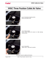
8. Check the air valve is in the “closed” position and connect the air supply from the com-
pressor

Page 16 of 64 General Machine Products Co., Inc.
9. Notify installation team that preparations are competed and that checking the air flow
through the sub-duct is about to commence.
10. Note: Only authorized fully trained operators should be allowed to operate the air
compressor.
With the air compressor ready to provide air, turn the air valve to the “open” position.
11. Confirm that air is being expelled from the far end of the sub-duct under pressure. If not
this indicates the run is too long, there is leak, an obstruction or the sub-duct is crushed
or otherwise damaged or disconnected. This must be remedied before any cable blowing
is undertaken, when confirmation is received, turn the air valve to the “closed” position
and shut down the compressor.

Page 17 of 64 General Machine Products Co., Inc.
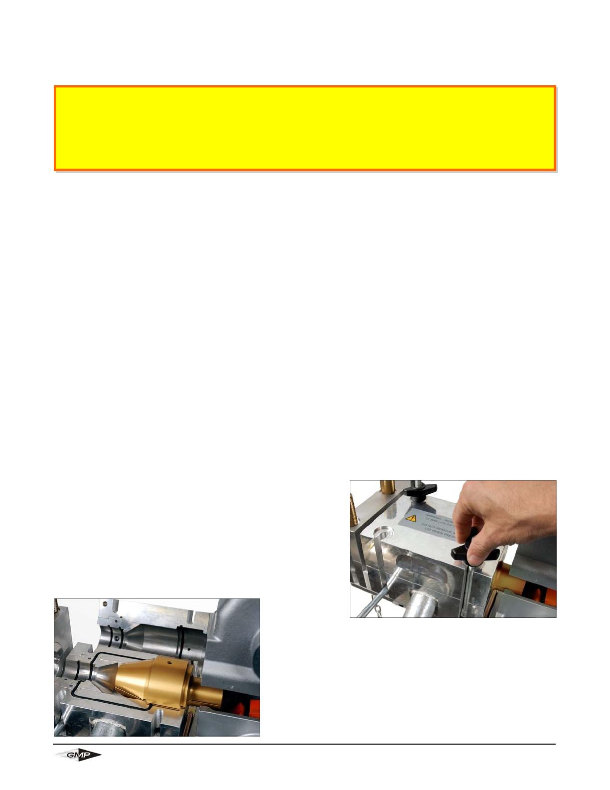
12. Ensure all air has exhausted from the air chamber
and sub-duct. Open the air chamber and sub-duct
clamp and withdraw the sub-duct. Add GMP’s Air-
Glide lubricant to the sub-duct at the rate of 1
quart (.95 liters) of lubricant per 2000 ft (600 m) of
sub-duct assuming a 1 1/4 bore. Adjust quantity
for different bore sizes. Note: Never open the air
chamber until the air pressure gauge reads
zero.
13. Insert a suitable foam plug into the sub-duct and
re-fit the sub-duct into the air chamber and secure
with the sub-duct clamp as already described. The
foam plug should be sized so as to be a snug fit in the
sub-duct. By blowing this plug down the sub-duct the
lubricant will be evenly distributed along the length of
the sub-duct. Before blowing the plug through the sub-
duct, ensure the sub-duct cable exit retaining device is
fitted at the end of the run, to prevent the plug flying
out of the open end of the sub-duct causing injury.
14. Re-fit the air chamber lid ensuring correct location on the dowels and tighten down the 4
retaining screws.

Page 18 of 64 General Machine Products Co., Inc.
15. NOTIFY INSTALLATION TEAM
Notify installation team that preparations for lubricating the sub-duct are complete and ready
to commence.
16. With the compressor ready to provide air, turn the air valve to the open position.
17. When the foam plug has been expelled from the
end or the sub-duct, turn the air valve to the “closed”
position and shut down the compressor. Allow the air
chamber and sub-duct to exhaust all the com-
pressed air. Note: Never open the air chamber un-
til the air pressure gauge reads zero.
18. Open the air chamber and remove the cable seal collet plug.
Page 19 of 64 General Machine Products Co., Inc.
6. OPERATING PROCEDURE
CABLE BLOWING
1. Position the Cable Blowing Machine in line with the proposed sub-duct.
2. Adjust the mounting frame to the desired height and angle by means of the front frame
supports. Withdraw the front “R” clip and retaining pin while supporting the weight of the
cable-blowing unit. Raise or lower the blowing unit and locate onto the support bar for the
desired position. Refit the retaining pin and “R” clip. Alternatively the blowing unit may be
detached from the trolley frame by withdrawing both “R” clips and retaining pins, while
supporting the weight of the blowing unit. The blowing unit can then be located in a trench,
manhole (depending on size) or at ground level. Ensure the blowing unit is stable and the
electronic panel is not immersed in water.
3. If trolley mounted, stabilize the frame on uneven ground by adjusting the height on the piv-
oting feet at the rear of the unit and locking in position.
Note: Care should be taken when wheeling the trolley around not to catch the ad-
justable feet pads on curbs or boulders, this may damage the pivoting foot.
4. Position the cable drum some 20 to 25 ft. (6 to 8 meters) directly behind and in line with
the cable blowing machine. (Cable carrying device to be suitably leveled and restrained).
5. Ensure the battery is fully charged before commencement of installation. The battery is
charged with the supplied charger thru the jack located on the right of the control panel.
6. Open tractor drive and unscrew retaining knobs on
the air chamber.
7. Open the air chamber lid on the pivot bolts.
Clean any debris, sludge, dirt, water, lubricant, etc.
from the air chamber, frame housing and cable intake
guide bracket assembly each time before use.
Lubricate both chains before use.
Clean both tractor drive belts before use.
Ensure cord seals are intact and not damaged
It is imperative that all persons using, operating or maintaining this cable blowing ma-
chine be fully trained and competent and authorized to do so and have read the entire
operation manual.
General Machine Products Co., Inc. and CBS Products Ltd, CANNOT BE HELD RE-
SPONSIBLE FOR MISUSE OF THIS EQUIPMENT.

Page 20 of 64 General Machine Products Co., Inc.
8. Unscrew the sub-duct clamp retaining bolts.
Refer to the Section 4 “SPECIFICATION” for
the correct pressure settings for the relief
valve and pressure switch and to Section 6
“MAINTENANCE” for the setting procedures.
NOTE: The cable blowing machine is sup-
plied as standard with the pressure relief
valve set at 1600 psi (110 Bar) and the
pressure switch set at 1450 psi (100 Bar),
these settings are suitable for cables in the range 12 - 32mm O.D.
For cables 6 - 12mm O.D. these settings need to be changed, refer to the section
4 “SPECIFICATION” for the correct pressure settings for the relief valve and
pressure switch and to section 6 “MAINTENANCE” for the pressure setting pro-
cedures.
9. Open the sub-duct clamp on the pivot bolts,
select and fit the correct size cable seal, sub duct
seal and sub duct clamp collets for the cable and
sub duct being used. (Refer to Tornado configu-
ration guide on page 58). Always check and
verify the correct size collets are fitted before
operating the blowing machine.
10. Place the sub-duct into the sub-duct seal collet
and sub-duct clamp collet. Ensure the sub-duct is
fully engaged into the sub-duct seal collet.
11. Clamp the sub-duct and tighten the two retaining
nuts. Remove the upper cable collet.
Page is loading ...
Page is loading ...
Page is loading ...
Page is loading ...
Page is loading ...
Page is loading ...
Page is loading ...
Page is loading ...
Page is loading ...
Page is loading ...
Page is loading ...
Page is loading ...
Page is loading ...
Page is loading ...
Page is loading ...
Page is loading ...
Page is loading ...
Page is loading ...
Page is loading ...
Page is loading ...
Page is loading ...
Page is loading ...
Page is loading ...
Page is loading ...
Page is loading ...
Page is loading ...
Page is loading ...
Page is loading ...
Page is loading ...
Page is loading ...
Page is loading ...
Page is loading ...
Page is loading ...
Page is loading ...
Page is loading ...
Page is loading ...
Page is loading ...
Page is loading ...
Page is loading ...
Page is loading ...
Page is loading ...
Page is loading ...
-
 1
1
-
 2
2
-
 3
3
-
 4
4
-
 5
5
-
 6
6
-
 7
7
-
 8
8
-
 9
9
-
 10
10
-
 11
11
-
 12
12
-
 13
13
-
 14
14
-
 15
15
-
 16
16
-
 17
17
-
 18
18
-
 19
19
-
 20
20
-
 21
21
-
 22
22
-
 23
23
-
 24
24
-
 25
25
-
 26
26
-
 27
27
-
 28
28
-
 29
29
-
 30
30
-
 31
31
-
 32
32
-
 33
33
-
 34
34
-
 35
35
-
 36
36
-
 37
37
-
 38
38
-
 39
39
-
 40
40
-
 41
41
-
 42
42
-
 43
43
-
 44
44
-
 45
45
-
 46
46
-
 47
47
-
 48
48
-
 49
49
-
 50
50
-
 51
51
-
 52
52
-
 53
53
-
 54
54
-
 55
55
-
 56
56
-
 57
57
-
 58
58
-
 59
59
-
 60
60
-
 61
61
-
 62
62


GMP 89000 Tornado Operation & Maintenance Manual
- Type
- Operation & Maintenance Manual
Ask a question and I''ll find the answer in the document
Finding information in a document is now easier with AI
Other documents
-
ISPRING 154KX2 User manual
-
TURBRO 707-90-011 Operating instructions
-
Crain 016 Owner's manual
-
OTC 4572 User manual
-
Precision GTX 36 User manual
-
 FADAL VH5C User manual
-
 LS META MEC Series User manual
-
Enwork Proxi 2.0 & Proxi Plus User guide
-
CAB Hermes applicators Operating instructions
-

