
Installation Instructions
Notice d’Installation
Instrucciones de Instalación
Trip breaker or remove fuse controlling the cir-
cuit on which you are working. Proper instal-
lation should comply with local electrical
codes. Use in dry indoor locations only.
CAUTION!
Before you start,
turn off power!
Installation Instructions
for B5 Starter Box
Installation Instructions
for B2, B3, B32, B35 Outlet Boxes
Installation Instructions for B4F
Ceiling Fan & Circular Fixture Box
B4F
B5
B6
B8
B2
B16
B3
B1
B7
The Wiremold Company
Consumer Products Division
60 Woodlawn Street
West Hartford, CT 06110
©1997 The Wiremold Company 41349 1197
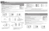
1. Remove the wall plate from existing switch
or outlet.
2. Remove the switch or outlet from existing in-wall
outlet box. Do not disconnect wires.
3. Place B5 starter box base over the switch or outlet
and fasten the base to the existing in-wall outlet
box (Figure A).
4. Being careful to include tongue on the base, mea-
sure and install lengths of B1 wire channel as
needed, using the instructions enclosed with the
B1 wire channel (Figure B).
5. Attach new wiring to the switch or outlet. (Black
wire to brass screw terminal, green wire to ground
screw or grounding provision used in existing in-
wall box) (Figure C).
6. Remove twistouts from B5 starter box cover to
accommodate B1 wire channel (Figure D).
7. Pull the switch or outlet through the B5 starter box
cover and screw the cover to the base (Figure E).
8. Mount the switch or outlet to the B5 starter
box cover.
9. Reattach the wall plate.
1. Mark mounting holes over stud (Figure G).
2. Drill pilot holes where marked (Figure H).
3. Connect B1 wire channel to mounting base.
(Figure I).
4. Remove the twistouts on the cover (Figure J) to
accommodate B1 wire channel.
FOR FAN BOX APPLICATIONS:
5. Insert 10-32 machine screws through raised holes
as shown from back of base. Screw on 10-32
sleeve nuts and tighten securely. (Figure K).
6. Install #12 wood screws through base into pre-
drilled holes. (Figure L).
1. Fasten outlet box base to wall using appropriate
fasteners (Figure F).
2. Attach new wiring (Figure C) to the new switch or
outlet (black wire to brass screw terminal, white
wire to silver screw terminal, green wire to green
ground screw).
3. Remove the twistouts on the outlet box cover
(Figure D) to accommodate B1 wire channel.
4. Pull the new switch or outlet through the outlet box
cover and screw the cover to the base (Figure E).
5. Mount the switch or outlet to the outlet box cover.
6. Attach the wall plate.
Important: Be sure to connect B1 wire
channel to box bases (B2, B3, B32, B35)
before mounting bases to surface.
Important: Be sure to connect B1 wire
channel to B4F outlet box base before
mounting bases to surface.
B
A
C
E
G
H
O
I
500
J
K
L
O
M
N
F
D
Important: Be sure to connect B1 wire
channel to box bases (B5) before mounting
bases to surface.
7. Attach ground wire (Figure M) through fan
bracket and cover to base with 10-32 ground
screw provided. Mount cover and fan bracket to
base using 10-32 lock nuts provided.
8. Discard remaining hardware (two 6-32 screws).
FOR FIXTURE APPLICATIONS:
5. Install #12 wood screws through base into pre-
drilled holes (Figure N).
6. Install two 6-32 machine screws and attach cover
to base (Figure O).
7. Discard remaining hardware (two 10-32 screws,
sleeve nuts and lock nuts).
1/8"
[3mm]
Page is loading ...
-
 1
1
-
 2
2


Legrand V700 Installation guide
- Type
- Installation guide
- This manual is also suitable for
Ask a question and I''ll find the answer in the document
Finding information in a document is now easier with AI
in other languages
- français: Legrand V700 Guide d'installation
- español: Legrand V700 Guía de instalación
Related papers
Other documents
-
Bell PTC521WH Operating instructions
-
-
Eaton 9501AW User manual
-
Eaton 9544SG Operating instructions
-
Heath Zenith SL-6015-WH5 Installation guide
-
-
 Kreg Precision Benchtop Router Table User manual
-
C2G 50190 Owner's manual
-
 Cooper Wiring Devices SFS15P-W-K Operating instructions
-
Viking 988946 Installation guide

