Honeywell DR4300 User manual
- Category
- Digital Video Recorders (DVR)
- Type
- User manual

Industrial Measurement and Control
DR4300
Circular Chart Recorder
Product Manual
44-01-25-14
12/03
Revision I

DR4300 Circular Chart Recorder
DR4300 Circular Chart Recorder Product Manual 12/03
ii
Copyright, Notices, and Trademark
Printed in U.S.A. – © Copyright 2003 by Honeywell
Revision I – December 2003
WARRANTY/REMEDY
Honeywell warrants goods of its manufacture as being free of defective materials and faulty
workmanship. Contact your local sales office for warranty information. If warranted goods are
returned to Honeywell during the period of coverage, Honeywell will repair or replace without charge
those items it finds defective. The foregoing is Buyer's sole remedy and is in lieu of all other
warranties, expressed or implied, including those of merchantability and fitness for a particular
purpose. Specifications may change without notice. The information we supply is believed to be
accurate and reliable as of this printing. However, we assume no responsibility for its use.
While we provide application assistance personally, through our literature and the Honeywell web
site, it is up to the customer to determine the suitability of the product in the application.
Industrial Measurement and Control
Honeywell
1100 Virginia Drive
Fort Washington, PA 19034
DR4300 and Accutune II are U.S. trademarks of Honeywell
Information Mapping is a trademark of Information Mapping Inc.
Modbus is a trademark of Modicon, Inc.
Other brands or product names are trademarks of their respective owners.

12/03 DR4300 Circular Chart Recorder Product Manual
iii
About This Document
Abstract
This manual contains instructions for installation, operation, and troubleshooting of the DR4300 Circular Chart Recorder.
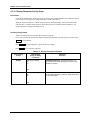
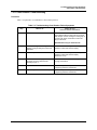
References
The following list identifies all documents that may be sources of reference for material discussed in this
publication.
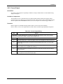
Document Title Doc ID
How to Apply Digital Instrumentation in Severe Electrical
Noise Environments
51-52-05-01
Modbus® RTU Serial Communications User Manual 51-52-25-66
Modbus® RTU Serial Communications User Manual
Configuration Interface for DR4300
51-52-25-71
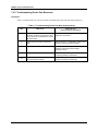
Contacts
World Wide Web
The following lists Honeywell’s World Wide Web sites that will be of interest to our customers.
Honeywell Organization WWW Address (URL)
Corporate http://www.honeywell.com
Industrial Measurement and Control http://www.honeywell.com/imc
International http://www.honeywell.com/Business/global.asp
Telephone
Contact us by telephone at the numbers listed below.
Organization Phone Number
United States and Canada Honeywell
1-800-423-9883 Tech. Support
1-888-423-9883 Q&A Faxback
(TACFACS)
1-800-525-7439 Service
DR4300 Circular Chart Recorder
DR4300 Circular Chart Recorder Product Manual 12/03
iv
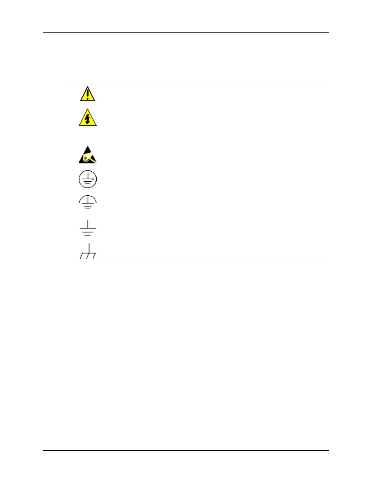
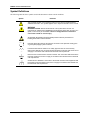
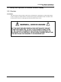
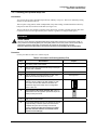
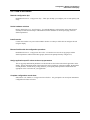
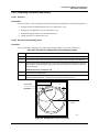
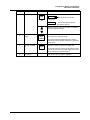
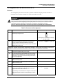
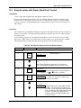
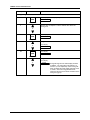
Symbol Definitions
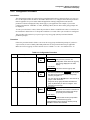
The following table lists those symbols used in this document to denote certain conditions.
Symbol Definition
This CAUTION symbol on the equipment refers the user to the Product Manual for
additional information. This symbol appears next to required information in the manual.
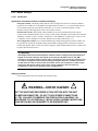
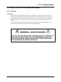
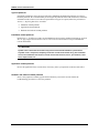
WARNING
PERSONAL INJURY: Risk of electrical shock. This symbol warns the user of a
potential shock hazard where HAZARDOUS LIVE voltages greater than 30 Vrms, 42.4
Vpeak, or 60 Vdc may be accessible. Failure to comply with these instructions
could result in death or serious injury.
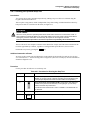
ATTENTION, Electrostatic Discharge (ESD) hazards. Observe precautions for
handling electrostatic sensitive devices
Protective Earth (PE) terminal. Provided for connection of the protective earth (green
or green/yellow) supply system conductor.
Functional earth terminal. Used for non-safety purposes such as noise immunity
improvement. NOTE: This connection shall be bonded to protective earth at the source
of supply in accordance with national local electrical code requirements.
Earth Ground. Functional earth connection. NOTE: This connection shall be bonded to
Protective earth at the source of supply in accordance with national and local electrical
code requirements.
Chassis Ground. Identifies a connection to the chassis or frame of the equipment shall
be bonded to Protective Earth at the source of supply in accordance with national and
local electrical code requirements.

12/03 DR4300 Circular Chart Recorder Product Manual
v
Contents
1. OVERVIEW .............................................................................................................. 1
1.1 Introduction .................................................................................................................................. 1
1.2 Model Number Breakdown ..........................................................................................................4
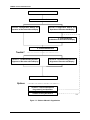
1.3 About This Manual....................................................................................................................... 9
2. INSTALLATION ..................................................................................................... 11
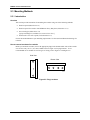
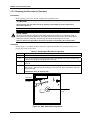
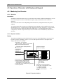
2.1 Overview .................................................................................................................................... 11
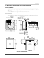
2.2 Mounting Considerations and Overall Dimensions.................................................................... 15
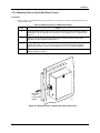
2.3 Mounting Methods ..................................................................................................................... 16
2.3.1 Introduction ................................................................................................................... 16
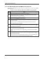
2.3.2 Mounting Flush in Panel (New Panel Cutout)............................................................... 17
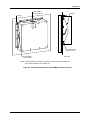
2.3.3 Panel Mounting Recorder with NEMA4 or Heavy Duty door ...................................... 18
2.3.4 Mounting on a 2-inch pipe ............................................................................................ 20
2.3.5 Mounting on Surface (of Panel or Wall) ....................................................................... 21
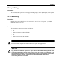
2.4 Wiring Prerequisites ................................................................................................................... 22
2.5 Input Wiring ............................................................................................................................... 27
2.5.1 Power Wiring................................................................................................................. 27
2.5.2 Analog Input Wiring...................................................................................................... 31
2.5.3 Digital Inputs (Optional) ............................................................................................... 33
2.5.4 Communication (Optional)............................................................................................ 35
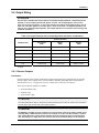
2.6 Output Wiring............................................................................................................................. 37
2.6.1 Discrete Outputs ............................................................................................................ 37
2.6.2 Current Output............................................................................................................... 41
2.6.3 Transmitter Power Out .................................................................................................. 43
3. CONFIGURATION, STARTUP, AND OPERATION OF BASIC RECORDER
WITHOUT DISPLAY .............................................................................................. 45
3.1 Overview .................................................................................................................................... 45
3.2 Configuration (Recording Set Up).............................................................................................. 46
3.2.1 Setting Configuration and Input Switches..................................................................... 46
3.2.2 Setting SW6 Switch 2.................................................................................................... 64
3.3 Startup and Operation of Recorder without Display .................................................................. 65
3.3.1 Overview ....................................................................................................................... 65
3.3.2 Preparing the Recorder for Operation............................................................................ 66
3.3.3 Running the Optional Step Test..................................................................................... 67
3.3.4 Startup............................................................................................................................ 69
4. CONFIGURATION, STARTUP AND OPERATION OF RECORDER WITH
DISPLAY ................................................................................................................ 71
4.1 Overview .................................................................................................................................... 71

DR4300 Circular Chart Recorder
DR4300 Circular Chart Recorder Product Manual 12/03
vi
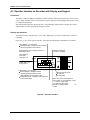
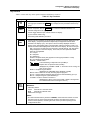
4.2 Operator Interface on Recorder with Display and Keypad......................................................... 72
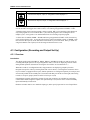
4.3 Configuration (Recording and Output Set Up)........................................................................... 74
4.3.1 Overview ....................................................................................................................... 74
4.3.2 Configuration Prompts .................................................................................................. 75
4.3.3 How to Get Started ........................................................................................................ 77
4.3.4 Configuration Tips......................................................................................................... 78
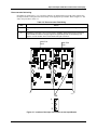
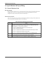
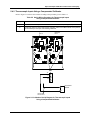
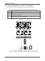
4.3.5 Switch Settings .............................................................................................................. 79
4.3.6 Configuration Procedure................................................................................................ 83
4.3.7 Input Parameters Set Up Group..................................................................................... 85
4.3.8 Pen Parameters Set Up Group ....................................................................................... 89
4.3.9 Chart Parameters Set Up Group .................................................................................... 90
4.3.10 Totalizer Parameters Set Up Group............................................................................... 91
4.3.11 Control Parameters Set Up Group ................................................................................. 94
4.3.12 Tuning Parameters Set Up Group................................................................................ 100
4.3.13 Setpoint Ramp/Program Set Up Group ....................................................................... 104
4.3.14 Timer Set Up Group .................................................................................................... 105
4.3.15 Alarms Set Up Group .................................................................................................. 106
4.3.16 Auxiliary Output Set Up Group................................................................................... 109
4.3.17 Communication Set Up Group .................................................................................... 111
4.3.18 Remote Switch (Digital Inputs) Set Up Group............................................................ 112
4.3.19 Display Parameter Set Up Group ................................................................................ 114
4.3.20 Lock Out Parameter Set Up Group.............................................................................. 115
4.3.21 Configuration Record Sheet ........................................................................................ 116
4.3.22 Limit Control Configuration........................................................................................ 118
4.4 Startup of Recorder with Display and Keypad ......................................................................... 119
4.4.1 Overview ..................................................................................................................... 119
4.4.2 Preparing the Recorder for Startup.............................................................................. 120
4.4.3 Running the Optional Step Test................................................................................... 121
4.4.4 Completing Preparation and Startup............................................................................ 123
4.5 Operation of Recorder with Display and Keypad..................................................................... 128
4.5.1 Monitoring Your Recorder .......................................................................................... 128
4.5.2 Operator Functions ...................................................................................................... 132
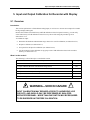
5. INPUT AND OUTPUT CALIBRATION FOR RECORDER WITH DISPLAY ........ 141
5.1 Overview .................................................................................................................................. 141
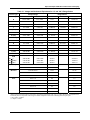
5.2 Input Calibration Minimum and Maximum Range Values ...................................................... 142
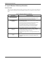
5.3 Input Calibration Preliminary Information............................................................................... 144
5.4 Input Calibration Set Up and Wiring........................................................................................ 146
5.4.1 General Calibration Set Up.......................................................................................... 146
5.4.2 Thermocouple Inputs Using a Compensated Calibrator.............................................. 147
5.4.3 Thermocouple Inputs Using an Ice Bath or Ice Point Reference................................. 148
5.4.4 RTD (Resistance Temperature Detector) Inputs ......................................................... 149
5.5 Input Calibration Procedure...................................................................................................... 151
5.6 Current Output Calibration....................................................................................................... 153
6. ROUTINE MAINTENANCE .................................................................................. 157

12/03 DR4300 Circular Chart Recorder Product Manual
vii
6.1 Overview .................................................................................................................................. 157
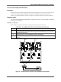
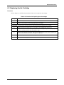
6.2 Replacing the Chart .................................................................................................................. 158
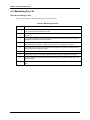
6.3 Replacing the Ink Cartridge...................................................................................................... 159
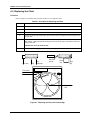
6.4 Maximizing Pen Life ................................................................................................................ 160
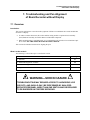
7. TROUBLESHOOTING AND PEN ALIGNMENT OF BASIC RECORDER
WITHOUT DISPLAY ............................................................................................ 161
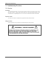
7.1 Overview .................................................................................................................................. 161
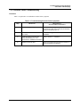
7.2 Observable Symptoms of Failure ............................................................................................. 163
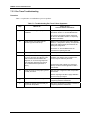
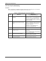
7.3 Troubleshooting Procedures ..................................................................................................... 164
7.3.1 Overview ..................................................................................................................... 164
7.3.2 Recorder Failure Troubleshooting............................................................................... 165
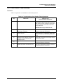
7.3.3 Pen Trace Troubleshooting.......................................................................................... 166
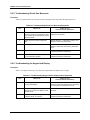
7.3.4 Chart Rotation Troubleshooting .................................................................................. 167
7.3.5 Troubleshooting Erratic Pen Movement...................................................................... 168
7.4 Alignment of Pen at Zero and 100 % ....................................................................................... 169
8. TROUBLESHOOTING AND PEN ALIGNMENT OF RECORDER WITH
DISPLAY .............................................................................................................. 171
8.1 Overview .................................................................................................................................. 171
8.2 Troubleshooting Aids ............................................................................................................... 173
8.3 Self Diagnostics........................................................................................................................ 174
8.3.1 Power up tests.............................................................................................................. 174
8.3.2 View Status of Tests .................................................................................................... 175
8.3.3 Background Tests ........................................................................................................ 176
8.3.4 Error Messages ............................................................................................................ 176
8.4 Observable Symptoms of Failure ............................................................................................. 179
8.5 Troubleshooting Procedures ..................................................................................................... 180
8.5.1 Overview ..................................................................................................................... 180
8.5.2 Recorder Failure Troubleshooting............................................................................... 181
8.5.3 Pen Trace Troubleshooting.......................................................................................... 182
8.5.4 Chart Rotation Troubleshooting .................................................................................. 183
8.5.5 Troubleshooting Erratic Pen Movement...................................................................... 184
8.5.6 Troubleshooting the Keypad and Display ................................................................... 184
8.5.7 Troubleshooting Relay Output .................................................................................... 185
8.5.8 Troubleshooting External Alarm Function.................................................................. 186
8.5.9 Troubleshooting Remote Switch (Digital Input) Function.......................................... 186
8.5.10 Troubleshooting Modbus Communications ................................................................ 187
8.6 Alignment of Pen at Zero and Span.......................................................................................... 188
9. PARTS LIST......................................................................................................... 191
9.1 Overview .................................................................................................................................. 191
9.2 Exploded Views........................................................................................................................ 192

DR4300 Circular Chart Recorder
DR4300 Circular Chart Recorder Product Manual 12/03
viii
A. ACCURACY ......................................................................................................... 199
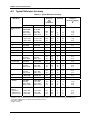
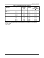
A.1 Overview .................................................................................................................................. 199
A.2 Typical Reference Accuracy..................................................................................................... 200
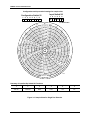
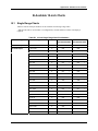
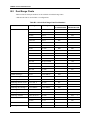
B. AVAILABLE 10-INCH CHARTS .......................................................................... 203
B.1 Single Range Charts ................................................................................................................. 203
B.2 Dual Range Charts.................................................................................................................... 208
C. SETPOINT RAMP/SOAK PROGRAMMING AND OPERATION......................... 211
C.1 Overview .................................................................................................................................. 211
C.2 Program Contents.................................................................................................................. 212
C.3 Drawing a Ramp/Soak Profile .................................................................................................. 214
C.4 Setpoint Program Prompt Hierarchy ........................................................................................ 218
C.5 Run/Monitor the Program......................................................................................................... 221
D. USING ACCUTUNE II .......................................................................................... 225
D.1 Overview .................................................................................................................................. 225
D.2 Starting and Stopping Tuning with Accutune II....................................................................... 226
D.3 Using Accutune with Duplex (Heat/Cool) Control .................................................................. 227
E. FOREIGN LANGUAGE SAFETY INSTRUCTIONS............................................. 229
F. HONEYWELL SERVICE CENTERS.................................................................... 241

12/03 DR4300 Circular Chart Recorder Product Manual
ix
Tables
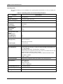
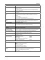
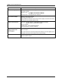
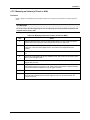
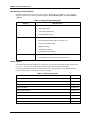
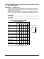
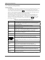
Table 2-1 Operating Limits and Condensed Specifications .......................................................................................12
Table 2-2 Mounting Flush in a New Panel Cutout.....................................................................................................17
Table 2-3 Procedure for Mounting Recorder with NEMA4 or Heavy Duty Door.....................................................18
Table 2-4 Pipe Mounting Procedure...........................................................................................................................20
Table 2-5 Mounting Flush on a Surface (of Panel or Wall) .......................................................................................21
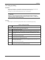
Table 2-6 Wiring Bundling Categories ......................................................................................................................26
Table 2-7 Wiring Illustrations ....................................................................................................................................26
Table 2-8 Procedure for Power Wiring Models .........................................................................................................28
Table 2-9 Analog Input Wiring ..................................................................................................................................31
Table 2-10 Digital Input Wiring.................................................................................................................................33
Table 2-11 Communication Wiring............................................................................................................................35
Table 2-12 Output Terminal Use for Output Algorithm and Option Combinations ..................................................37
Table 2-13 Relay Output Wiring - 1 or 2 Pen Models ...............................................................................................38
Table 2-14 Current Output Wiring .............................................................................................................................41
Table 2-15 Transmitter Power Out Wiring.................................................................................................................43
Table 3-1 Procedure for Configuring Model without Display ...................................................................................46
Table 3-2 Configuration and Input Switch Settings for Models without Display ......................................................49
Table 3-3 Preparing the Recorder for Operation ........................................................................................................66
Table 3-4 Procedure for Running the Step Test .........................................................................................................67
Table 3-5 Startup Procedure.......................................................................................................................................69
Table 4-1 Key Functions ............................................................................................................................................73
Table 4-2 Configuration Tips .....................................................................................................................................78
Table 4-3 SW6 Input Switch Settings for Models Having Display and Keypad ......................................................80
Table 4-4 Configuration Procedure ............................................................................................................................83
Table 4-5 Input Parameter Definitions .......................................................................................................................85
Table 4-6 Pen Parameter Definitions..........................................................................................................................89
Table 4-7 Chart Parameter Definitions.......................................................................................................................90
Table 4-8 Totalizer Function Definitions ...................................................................................................................91
Table 4-9 Control Parameter Definitions ...................................................................................................................94
Table 4-10 Tuning Parameter Definitions ................................................................................................................101
Table 4-11 Setpoint Ramp Parameter Definitions....................................................................................................104
Table 4-12 Timer Parameter Definitions..................................................................................................................105
Table 4-13 Alarm Parameter Definitions .................................................................................................................106
Table 4-14 Auxiliary Output Parameter Definitions ................................................................................................109
Table 4-15 Communication Parameter Definitions ..................................................................................................111
Table 4-16 Remote Switch Parameter Definitions ...................................................................................................113
Table 4-17 Display Parameter Definitions ...............................................................................................................114
Table 4-18 Lockout Parameter Definitions ..............................................................................................................115
Table 4-19 Limit Control Parameter Definitions......................................................................................................118
Table 4-20 Preparing the Recorder for Operation ....................................................................................................120
Table 4-21 Procedure for Running the Step Test .....................................................................................................121
Table 4-22 Procedure for Setting Chart Time and Applying Power ........................................................................123
Table 4-23 Power-Up Diagnostic Tests....................................................................................................................124
Table 4-24 Procedure for Testing the Displays and Keys ........................................................................................125
Table 4-25 Procedure for Starting the Recorder.......................................................................................................126
Table 4-26 Meaning of Indicators ............................................................................................................................129
Table 4-27 Lower Display Operating Parameter Labels ..........................................................................................130
Table 4-28 Error Messages.......................................................................................................................................131
Table 4-29 Procedure for Selecting Automatic or Manual Mode ............................................................................133
Table 4-30 Procedure for Changing the Control Setpoints ......................................................................................134
Table 4-31 Procedure for Displaying or Changing the Alarm Setpoints..................................................................135
Table 4-32 Procedure for Selecting Factory or Field Calibration Values ................................................................136

DR4300 Circular Chart Recorder
DR4300 Circular Chart Recorder Product Manual 12/03
x
Table 4-33 Procedure for Resetting Totalizer ..........................................................................................................137
Table 4-34 Procedure for Starting Timer .................................................................................................................138
Table 4-35 Procedure for Resetting Limit Controller...............................................................................................139
Table 5-1 Voltage and Resistance Equivalents for 0 % and 100 % Range Values ..................................................143
Table 5-2 Equipment Needed for Calibration ..........................................................................................................144
Table 5-3 Disconnect the Field Wiring ....................................................................................................................145
Table 5-4 General Calibration Set Up Procedure.....................................................................................................146
Table 5-5 Set Up Wiring Procedure for Thermocouple Inputs Using a Compensated Calibrator ..........................147
Table 5-6 Set Up Wiring Procedure for Thermocouple Inputs Using an Ice Bath...................................................148
Table 5-7 Set Up Wiring Procedure for Calibrating RTD Inputs.............................................................................149
Table 5-8 Set Up Wiring Procedure for Calibrating Millivolts, Volts, and Milliamps Inputs .................................150
Table 5-9 Input Calibration Procedure Sequence.....................................................................................................151
Table 5-10 Set Up Wiring Procedure for Current Proportional Output ...................................................................153
Table 5-11 Procedure for Calibrating Current Output..............................................................................................154
Table 6-1 Procedure for Replacing the Chart...........................................................................................................158
Table 6-2 Procedure for Replacing the Ink Cartridge ..............................................................................................159
Table 6-3 Maximizing Pen Life................................................................................................................................160
Table 7-1 Observable Symptoms of Failure.............................................................................................................163
Table 7-2 Troubleshooting Recorder Failure Symptoms .........................................................................................165
Table 7-3 Troubleshooting Pen Trace Failure Symptoms ........................................................................................166
Table 7-4 Troubleshooting Chart Rotation Failure Symptoms ................................................................................167
Table 7-5 Troubleshooting Erratic Pen Movement Symptoms ................................................................................168
Table 7-6 Procedure for Pen Alignment...................................................................................................................169
Table 8-1 Procedure for Identifying the Software Version ......................................................................................173
Table 8-2 Power-Up Diagnostic Tests......................................................................................................................174
Table 8-3 Procedure for Displaying the Results of Self-Diagnostics.......................................................................175
Table 8-4 Error Messages.........................................................................................................................................177
Table 8-5 Observable Symptoms of Failure.............................................................................................................179
Table 8-6 Troubleshooting Recorder Failure Symptoms .........................................................................................181
Table 8-7 Troubleshooting Pen Trace Failure Symptoms ........................................................................................182
Table 8-8 Troubleshooting Chart Rotation Failure Symptoms ................................................................................183
Table 8-9 Troubleshooting Erratic Pen Movement Symptoms ................................................................................184
Table 8-10 Troubleshooting Keypad and/or Display Failure Symptoms .................................................................184
Table 8-11 Troubleshooting Relay Output Failure Symptoms.................................................................................185
Table 8-12 Troubleshooting External Alarm Function Failure Symptoms ..............................................................186
Table 8-13 Troubleshooting Remote Switch (Digital Input) Function Failure Symptoms ......................................186
Table 8-14 Troubleshooting Modbus Communications ...........................................................................................187
Table 8-15 Procedure for Aligning Pen at Zero and Span .......................................................................................188
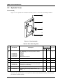
Table 9-1 Door Assembly Parts................................................................................................................................192
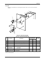
Table 9-2 Chart Plate Assembly Parts......................................................................................................................193
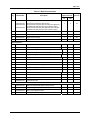
Table 9-3 Basic Recorder Parts ................................................................................................................................195
Table A-1 Typical Reference Accuracy ...................................................................................................................200
Table B-1 10-inch Single Range Chart Part Numbers..............................................................................................203
Table B-2 10-inch Dual Range Chart Part Numbers................................................................................................208
Table C-1 Prompt Hierarchy and Available Selections............................................................................................218
Table C-2 Run/Monitor Functions ...........................................................................................................................221
Table D-1 Procedure for Starting Accutune II .........................................................................................................226
Table D-2 Procedure for Using Accutune for Duplex Control ................................................................................227

12/03 DR4300 Circular Chart Recorder Product Manual
xi
Figures
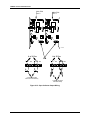
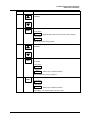
Figure 1-1 Guide to Manual’s Organization...............................................................................................................10
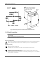
Figure 2-1 Overall Dimensions ..................................................................................................................................15
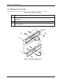
Figure 2-2 Plug Locations ..........................................................................................................................................16
Figure 2-3 Mounting Flush in a New Panel Cutout (Rear View)...............................................................................17
Figure 2-4 Panel Mounting Recorder with NEMA4 or Heavy Duty Door ................................................................19
Figure 2-5 Pipe Mounting Brackets............................................................................................................................20
Figure 2-6 Mounting Flush on a Surface of Panel or Wall (Rear View)....................................................................22
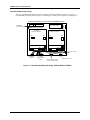
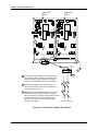
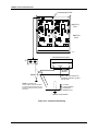
Figure 2-7 Recommended Wiring Routing - Models Without CE Mark ...................................................................24
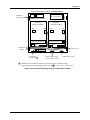
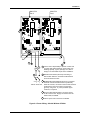
Figure 2-8 Recommended Wiring Routing - Models With CE Mark ........................................................................25
Figure 2-9 Power Wiring – Models Without CE Mark ..............................................................................................29
Figure 2-10 Power Wiring – Models With CE Mark .................................................................................................30
Figure 2-11 Analog Input Wiring...............................................................................................................................32
Figure 2-12 Digital Input Wiring ...............................................................................................................................34
Figure 2-13 Communication Wiring ..........................................................................................................................36
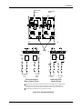
Figure 2-14 Relay Output Wiring...............................................................................................................................39
Figure 2-15 Open Collector Output Wiring ...............................................................................................................40
Figure 2-16 Current Output Wiring............................................................................................................................42
Figure 2-17 Transmitter Power Out Wiring ...............................................................................................................44
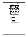
Figure 3-1 Location of Configuration and Input Switches.........................................................................................47
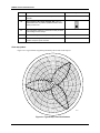
Figure 3-2 Sample Chart for Single Pen Recorder .....................................................................................................48
Figure 3-3 Basic Chart Plate Components..................................................................................................................66
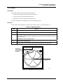
Figure 3-4 Typical Step Test Chart Patterns...............................................................................................................68
Figure 3-5 Setting Chart Time to Time Index ............................................................................................................69
Figure 4-1 Operator Interface.....................................................................................................................................72
Figure 4-2 Prompt Hierarchy......................................................................................................................................75
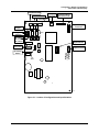
Figure 4-3 Location of Switches and Relays..............................................................................................................82
Figure 4-4 Basic Chart Plate Components................................................................................................................120
Figure 4-5 Typical Step Test Chart Patterns.............................................................................................................122
Figure 4-6 Setting Chart Time to Time Index ..........................................................................................................123
Figure 4-7 Operator Interface...................................................................................................................................128
Figure 5-1 Location of the Input Connections on the Input Boards.........................................................................145
Figure 5-2 Calibration Set Up Diagram for Thermocouple Inputs Using a Compensated Calibrator.....................147
Figure 5-3 Calibration Set Up Diagram for Thermocouple Inputs Using an Ice Bath .............................................148
Figure 5-4 Calibration Set Up Diagram for RTD Inputs..........................................................................................149
Figure 5-5 Calibration Set Up Diagram for Millivolts, Volts, and Milliamps Inputs...............................................150
Figure 5-6 Test Equipment Connections for Calibrating Current Output ................................................................153
Figure 6-1 Replacing the Chart and Ink Cartridge ...................................................................................................158
Figure 9-1 Door Assembly .......................................................................................................................................192
Figure 9-2 Chart Plate Assembly..............................................................................................................................193
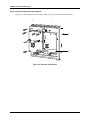
Figure 9-3 Recorder Components.............................................................................................................................194
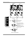
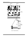
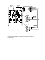
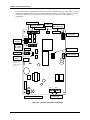
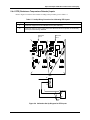
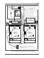
Figure 9-4 DR4300 Recorder (CE Mark) – Internal Cabling Diagram....................................................................196
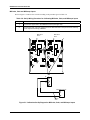
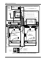
Figure 9-5 DR4300 Recorder (Non-CE Mark) – Internal Cabling Diagram............................................................197
Figure C-1 Ramp/Soak Profile Example ..................................................................................................................214

DR4300 Circular Chart Recorder
DR4300 Circular Chart Recorder Product Manual 12/03
xii

Overview
12/03 DR4300 Circular Chart Recorder Product Manual
1
1. Overview
1.1 Introduction
Function
The DR4300 recorder is a one or two pen microprocessor-based circular chart recorder. The basic DR4301
(one pen) and DR4302 (two pen) recorders provide reliable, convenient pen-drawn analog traces on
preprinted 10 inch (250 mm) charts. Both the chart and the pens are driven by stepper motors controlled by
the microprocessor. Chart speed and range are configurable. The basic recorder is also available in CE
models DR4321 (one pen) and DR4322 (two pen).
In addition to generating pen-drawn chart traces, the DR4311 (one pen) and DR4312 (two pen) models
include a display and keypad. This option lets you display the real time value of the process variable for
each pen channel, as well as other values. The recorder with display and keypad is also available in CE
models DR4331 (one pen) and DR4332 (two pen).
Each pen channel has its own printed circuit assembly (PCA), allowing the channels to operate
independently.
CE conformity (Europe)
Indicated models of this product are in conformity with the protection requirements of the following
European Council Directives: 73/23/EEC, the Low Voltage Directive, and 89/336/EEC, the EMC
Directive. Conformity of this product with any other “CE Mark” Directive(s) shall not be assumed.
Deviation from the installation conditions specified in this manual, and the special conditions for CE
conformity in Section 2 of this manual, may invalidate this product’s conformity with the Low Voltage and
EMC Directives.
Analog inputs
The input for each pen channel can be one of any standard electrical signal: milliamp, millivolt, voltage,
RTD, or thermocouple. The input type and range are configurable. In the models having display and
keypad the range can be expanded and compressed to meet specific measurement needs. The display and
keypad also permit entry of input bias and filter values. (The input filter for the models without a display is
fixed at one second; their bias is zero.)
Digital inputs
Two digital inputs for each pen channel are available as an option. These inputs can be used to trigger the
switchover to a second control setpoint or a pre-configured constant output if an external event causes
contact closure (sets the digital input to ON). In addition, the digital inputs can be used to remotely reset
the optional totalizer or limit controller.

DR4300 Circular Chart Recorder
DR4300 Circular Chart Recorder Product Manual 12/03
2
Communications
The Modbus communication option permits configuration of the unit and monitoring of process variables
over a standard multi-drop serial communications link.
Relay outputs for control and alarms
The models with display and keypad are available with output relays, two for each pen channel. These
relays can be wired for Normally Open (NO) and Normally Closed (NC) terminals. ON-OFF control can
be performed using one relay (relay simplex control) or two relays (relay duplex control).
Any relay not used for control is available for alarming. Two alarm setpoints can be configured for each
alarm relay. An adjustable hysteresis of 0.0 % to 100.0 % is configurable for the alarm setpoint.
Analog output for control or retransmission
Depending on the model ordered, a 4 to 20 mA current output may be available for control or
retransmission of a process variable (“auxiliary output”).
Failsafe operation
The control function can operate in automatic or manual mode. In automatic the control function works to
maintain the process variable at the setpoint entered locally by the operator. During configuration a
“failsafe” value can be specified. This value is used as the output at power up and in case of input failure
during automatic operation. (When the unit goes to failsafe, the control function goes to manual mode.)
In manual mode the operator enters the output locally. If the recorder has gone to failsafe operation, the
operator will be able to change the output value from the failsafe value specified during configuration.
Timer and totalizer options
The recorder is available with timer and totalizer options. The timer can be started locally, remotely, or by
an alarm. The unit can be configured to display elapsed time or time remaining. At the end of the timeout
period Relay 2 is energized, and remains energized until the timer is reset. The totalizer can be reset
locally or remotely; its displayed value can be scaled.
Setpoint Programming Option
The recorder is available with a Setpoint Program option. This feature allows configuration of up to four
setpoint programs using a total of twenty-four ramp and soak segments. A setpoint and time is configured
for each segment. The program can be set up to include guaranteed soak segments. A plus/minus
deviation is configured for all soak segments. Whenever the plus/minus deviation is exceeded, soak timing
is frozen.
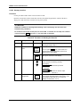
Display and keypad
In addition to process variables, the display can show output, setpoint, and deviation real time values if the
recorder is equipped with optional outputs. The upper display uses four characters to display the input
value. The lower display shows other parameters using a two- or three-character label and four- or three-
digit values. In addition, status and error messages flash on the lower display when necessary.

Overview
12/03 DR4300 Circular Chart Recorder Product Manual
3
The six keys are used to select the real time value to be displayed, and to select set up parameters and their
values during configuration. The display and keypad are behind the door, protecting them from dirt.
A supplementary external keypad is also available.
For more information about the operator interface on models having a display and keypad, see Subsection
4.2.
Configuration
The models without a display are configured with two switchbanks: one for configuration, the other for
input definition. Configuration is a simple matter of consulting a table in this manual; selecting the
appropriate combination of range, chart speed, engineering unit, and input type; then setting the switches as
shown in the table.
The display and keypad are used to configure models with these options. When the unit is in configuration
mode, set up parameters are displayed, and grouped by function. Designate site-specific values by selecting
them from a list of choices, or entering them as numeric values. The operator can be locked out from
making configuration changes.
The models with display also use a switchbank to define the type of input to be expected by the hardware.
Input parameters used by the software are configured using the display and keypad.
Self-diagnostics
All DR4300 recorders run self-diagnostics at power up and in the background during normal operation.
Problems are reported by error messages on the display when present. An LED in the models without a
display lights if the unit fails a self-diagnostic.
Construction
All DR4300 recorders are housed in a rugged molded case which can be panel-, pipe- or surface-mounted.
An acrylic-windowed, gasketed door protects internal components from harsh environments while
allowing easy access to the chart.

DR4300 Circular Chart Recorder
DR4300 Circular Chart Recorder Product Manual 12/03
4
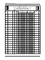
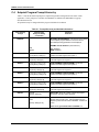
1.2 Model Number Breakdown
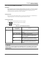
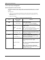
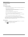
Introduction
The model number breakdown is presented in the tables that follow. Note that not all options are available
with all recorders. Check the “Availability” column for each model. A star () in the Availability column
means unrestricted availability of the feature for that model. N/A indicates the feature is not available for
that model. A letter in the Availability column denotes restricted availability. The meaning of each letter is
provided at the bottom of this page.
The Notes referred to in the tables are also at the end of this subsection.
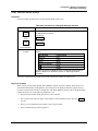
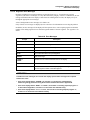
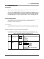
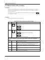
Model number format
The basic model number consists of a key number. Appended to this key number are characters that
identify the features in various categories. The meaning of the characters in each category is presented in a
table identified below.
Key Number Table I Table II Table III Table IV Table V Table VI
DR43_ _ - _ _ _ _ - _ _ _ _ _ - _ _ _ _ - _ _ _ _ - _ _ - 000
Key numbers
The base model numbers for the DR4300 Circular Chart Recorder are:
One Pen Recorder (Basic Recorder Without Display) DR4301
Two Pen Recorder (Basic Recorder Without Display) DR4302
One Pen Recorder (With Display) DR4311
Two Pen Recorder (With Display) DR4312
One Pen Recorder (Basic Recorder Without Display, With CE Mark) DR4321
Two Pen Recorder (Basic Recorder Without Display, With CE Mark) DR4322
One Pen Recorder (With Display, With CE Mark) DR4331
Two Pen Recorder (With Display, With CE Mark) DR4332
Restricted availability designations
d = Not available with Table I selection XX0X.
e = Not available with Table I selection XXX0.
f = Not available with Table I selection 0XXX.
g = Not available with Table I selection 0000.
h = Not available with Table I selections FXXX, XFXX, GXXX, XGXX.
j = Not available with Table I selection 0XXX.
k = Not available with Table I selection X0XX.
m = Not available with Table I selections 2XXX, 3XXX, 4XXX, 5XXX, AXXX, XXX0.
n = Not available with Table II selection SXXXX.
p = Not available with Table II selections RXXXX, SXXXX.
q = Not available with Table II selections GXXXX, BXXXX, HXXXX, CXXXX, KXXXX, LXXXX.

Overview
12/03 DR4300 Circular Chart Recorder Product Manual
5
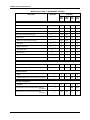
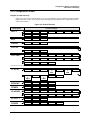
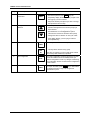
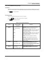
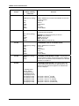
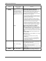
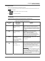
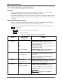
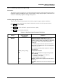
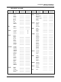
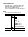
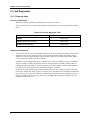
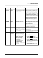
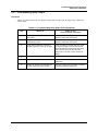
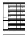
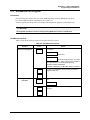
Model Number Table I - OUTPUT
Description Model No. Availability
4301
4321
4302
4322
4311
4331
4312
4332
Pen One
None 0 _ _ _
2 Outputs (Alarm/On-Off Control) 2 _ _ _ N/A N/A d d
1 PID Control with Accutune II (see Note 1) 3 _ _ _ N/A N/A d d
1 PID Control/Setpoint Program/Timer(see Note 1) 4 _ _ _ N/A N/A d d
2 Outputs (Alarm 1 and Timer) 5 _ _ _ N/A N/A d d
4 to 20 mA Retransmission Output (see Note 4) A _ _ _ N/A N/A d d
FM Approved Limit Control F _ _ _ N/A N/A d d
FM Approved Limt Control/Timer Output G _ _ _ N/A N/A d d
Pen Two
None _ 0 _ _
2 Outputs (Alarm/On-Off Control) _ 2 _ _ N/A N/A N/A e
1 PID Control with Accutune II (see Note 1) _3 _ _ N/A N/A N/A e
1 PID Control/Setpoint Program/Timer(see Note 1) _ 4 _ _ N/A N/A N/A e
2 Outputs (Alarm 1 and Timer) _ 5 _ _ N/A N/A N/A e
4 to 20 mA Retransmission Output (see Note 4) _ A _ _ N/A N/A N/A e
FM Approved Limit Control _ F _ _ N/A N/A N/A m
FM Approved Limt Control/Timer Output _ G _ _ N/A N/A N/A m
Output Type Pen 1
None _ _ 0 _
Electromechanical Relay _ _ E _ N/A N/A j j
Solid State Relay _ _ S _ N/A N/A j j
Open Collector _ _ T _ N/A N/A j j
Output Type Pen 2
None _ _ _ 0
Electromechanical Relay _ _ _ E N/A N/A N/A k
Solid State Relay _ _ _ S N/A N/A N/A k
Open Collector _ _ _ T N/A N/A N/A k

DR4300 Circular Chart Recorder
DR4300 Circular Chart Recorder Product Manual 12/03
6
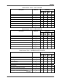
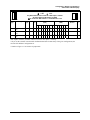
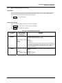
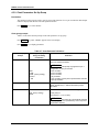
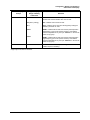
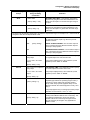
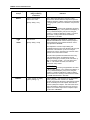
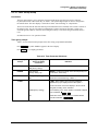
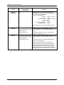
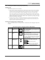
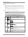
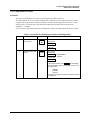
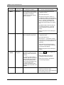
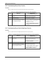
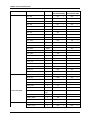
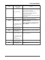
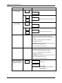
Model Number Table II - INSTRUMENT OPTIONS
Description Model No. Availability
4301
4321
4302
4322
4311
4331
4312
4332
Door Options
Gray Door G _ _ _ _
Blue Door B _ _ _ _
Gray Door with External Keypad H _ _ _ _ N/A N/A
Blue Door with External Keypad C _ _ _ _ N/A N/A
Black Door K _ _ _ _
Black Door with External Keypad L _ _ _ _ N/A N/A
SST Door R _ _ _ _
NEMA 4 SST Door S _ _ _ _
Standard Latch _ 0 _ _ _ n n n n
Keyed Latch _ A _ _ _
Keyed Latch/Chart Plate Seal _ B _ _ _ q q q q
Door Lock _ K _ _ _ p p p p
Instrument Power/Transmitter Power
Universal Recorder Power _ _ 1 _ _
Universal Power +24 Vdc Transmitter Power _ _ 3 _ _
Communications
None _ _ _ 0 _
RS485 Modbus RTU Communication (see Note 5) _ _ _ C _
Product Configuration
Standard _ _ _ _ 0
Configuration for Non-Standard Range Settings
(see Note 6)
_ _ _ _ 1
N/A N/A
Configuration for Customer's Specific Data
(see Note 6)
_ _ _ _ 2 N/A N/A
Overview
12/03 DR4300 Circular Chart Recorder Product Manual
7
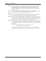
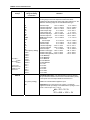
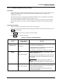
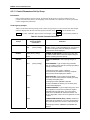
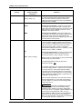
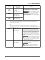
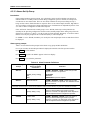
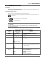
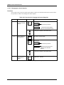
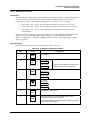
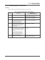
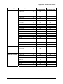
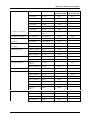
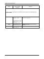
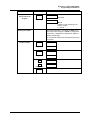
Model Number Table III - PEN 1 OPTIONS
Description Model No. Availability
4301
4321
4302
4322
4311
4331
4312
4332
No Digital Inputs 0 _ _ _
Digital Inputs (See Note 3) D _ _ _ N/A N/A f g
None _ 0 _ _
No Totalizer Function _ _ 0 _
Totalizer _ _ T _ N/A N/A h h
Future _ _ _ 0
Model Number Table IV - PEN 2 OPTIONS
Description Model No. Availability
4301
4321
4302
4322
4311
4331
4312
4332
No Digital Inputs 0 _ _ _
Digital Inputs (See Note 3) D _ _ _ N/A N/A N/A g
None _ 0 _ _
No Totalizer Function _ _ 0 _
Totalizer _ _ T _ N/A N/A N/A h
Future _ _ _ 0
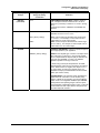
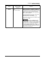
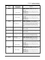
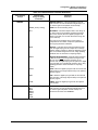
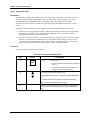
Model Number Table V - APPROVALS/CERTIFICATES
Description Model No. Availability
4301
4321
4302
4322
4311
4331
4312
4332
No Approvals 0 _
UL Listing U _ n n n n
CSA Certification C _ n n n n
UL and CSA Approved B _ n n n n
No Certificate _ 0
Certificate of Conformance (F3391) _ 1
Certificate of Calibration (F3399) (See Note 2) _ 2
Certificate of Conformance and Calibration
(See Note 2)
_ 3

DR4300 Circular Chart Recorder
DR4300 Circular Chart Recorder Product Manual 12/03
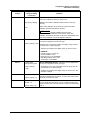
8
NOTE 1: PID control options include current output plus two discrete outputs for alarms. If ON-OFF or
time-proportioned simplex control is used, only one discrete output is available for an alarm.
Time-proportioned duplex control requires the use of both outputs and therefore no relay
outputs are available for alarms on that pen channel. Accutune II tuning is a standard feature
with PID control options.
NOTE 2: Customer must supply the input actuation and range information for each input in the Free Form
section of the order to have the unit supplied with a Certificate of Calibration.
NOTE 3: Digital Inputs are only available when ordering outputs in Table I.
NOTE 4: 4 to 20 mA Retransmission Output includes two outputs per pen for alarms. You must specify
the type of alarm outputs required (i.e., Relay, SS Relay, Open Collector Outputs).
NOTE 5: On key numbers DR4301, DR4302, DR4321, and DR4322 the communication address is fixed;
the display assembly is required to change it. Only one DR4301 or DR4321 instrument, or only
one pen of a DR4302 or DR4322 can exist on the network, otherwise communication conflicts
will exist. Pen 1 is the default when communications is specified on these models.
NOTE 6: Recorder is supplied with one box of 30755820-001, 0 to 100 Even "starter" charts. For special
range configuration on the DR4301, DR4302, DR4321, or DR4322 Recorder, provide the Input
Type, Chart Range, Chart Speed, °C or °F, Engineering Units, Linear or Non-Linear Chart Type
when ordering.
For example: Pen 1: "J" Thermocouple, 0-375 °F, 7-Day Linear Chart
Pen 2: 4-20 mA, 0-1000, 7-Day Linear Chart
For configuration on Models DR4311, DR4312, DR4331, and DR4332, the customer must
supply completed "Configuration Worksheets" with order for units to be Factory configured.
Page is loading ...
Page is loading ...
Page is loading ...
Page is loading ...
Page is loading ...
Page is loading ...
Page is loading ...
Page is loading ...
Page is loading ...
Page is loading ...
Page is loading ...
Page is loading ...
Page is loading ...
Page is loading ...
Page is loading ...
Page is loading ...
Page is loading ...
Page is loading ...
Page is loading ...
Page is loading ...
Page is loading ...
Page is loading ...
Page is loading ...
Page is loading ...
Page is loading ...
Page is loading ...
Page is loading ...
Page is loading ...
Page is loading ...
Page is loading ...
Page is loading ...
Page is loading ...
Page is loading ...
Page is loading ...
Page is loading ...
Page is loading ...
Page is loading ...
Page is loading ...
Page is loading ...
Page is loading ...
Page is loading ...
Page is loading ...
Page is loading ...
Page is loading ...
Page is loading ...
Page is loading ...
Page is loading ...
Page is loading ...
Page is loading ...
Page is loading ...
Page is loading ...
Page is loading ...
Page is loading ...
Page is loading ...
Page is loading ...
Page is loading ...
Page is loading ...
Page is loading ...
Page is loading ...
Page is loading ...
Page is loading ...
Page is loading ...
Page is loading ...
Page is loading ...
Page is loading ...
Page is loading ...
Page is loading ...
Page is loading ...
Page is loading ...
Page is loading ...
Page is loading ...
Page is loading ...
Page is loading ...
Page is loading ...
Page is loading ...
Page is loading ...
Page is loading ...
Page is loading ...
Page is loading ...
Page is loading ...
Page is loading ...
Page is loading ...
Page is loading ...
Page is loading ...
Page is loading ...
Page is loading ...
Page is loading ...
Page is loading ...
Page is loading ...
Page is loading ...
Page is loading ...
Page is loading ...
Page is loading ...
Page is loading ...
Page is loading ...
Page is loading ...
Page is loading ...
Page is loading ...
Page is loading ...
Page is loading ...
Page is loading ...
Page is loading ...
Page is loading ...
Page is loading ...
Page is loading ...
Page is loading ...
Page is loading ...
Page is loading ...
Page is loading ...
Page is loading ...
Page is loading ...
Page is loading ...
Page is loading ...
Page is loading ...
Page is loading ...
Page is loading ...
Page is loading ...
Page is loading ...
Page is loading ...
Page is loading ...
Page is loading ...
Page is loading ...
Page is loading ...
Page is loading ...
Page is loading ...
Page is loading ...
Page is loading ...
Page is loading ...
Page is loading ...
Page is loading ...
Page is loading ...
Page is loading ...
Page is loading ...
Page is loading ...
Page is loading ...
Page is loading ...
Page is loading ...
Page is loading ...
Page is loading ...
Page is loading ...
Page is loading ...
Page is loading ...
Page is loading ...
Page is loading ...
Page is loading ...
Page is loading ...
Page is loading ...
Page is loading ...
Page is loading ...
Page is loading ...
Page is loading ...
Page is loading ...
Page is loading ...
Page is loading ...
Page is loading ...
Page is loading ...
Page is loading ...
Page is loading ...
Page is loading ...
Page is loading ...
Page is loading ...
Page is loading ...
Page is loading ...
Page is loading ...
Page is loading ...
Page is loading ...
Page is loading ...
Page is loading ...
Page is loading ...
Page is loading ...
Page is loading ...
Page is loading ...
Page is loading ...
Page is loading ...
Page is loading ...
Page is loading ...
Page is loading ...
Page is loading ...
Page is loading ...
Page is loading ...
Page is loading ...
Page is loading ...
Page is loading ...
Page is loading ...
Page is loading ...
Page is loading ...
Page is loading ...
Page is loading ...
Page is loading ...
Page is loading ...
Page is loading ...
Page is loading ...
Page is loading ...
Page is loading ...
Page is loading ...
Page is loading ...
Page is loading ...
Page is loading ...
Page is loading ...
Page is loading ...
Page is loading ...
Page is loading ...
Page is loading ...
Page is loading ...
Page is loading ...
Page is loading ...
Page is loading ...
Page is loading ...
Page is loading ...
Page is loading ...
Page is loading ...
Page is loading ...
Page is loading ...
Page is loading ...
Page is loading ...
Page is loading ...
Page is loading ...
Page is loading ...
Page is loading ...
Page is loading ...
Page is loading ...
Page is loading ...
Page is loading ...
Page is loading ...
Page is loading ...
Page is loading ...
Page is loading ...
Page is loading ...
Page is loading ...
Page is loading ...
Page is loading ...
Page is loading ...
Page is loading ...
Page is loading ...
Page is loading ...
Page is loading ...
Page is loading ...
Page is loading ...
Page is loading ...
Page is loading ...
Page is loading ...
Page is loading ...
-
 1
1
-
 2
2
-
 3
3
-
 4
4
-
 5
5
-
 6
6
-
 7
7
-
 8
8
-
 9
9
-
 10
10
-
 11
11
-
 12
12
-
 13
13
-
 14
14
-
 15
15
-
 16
16
-
 17
17
-
 18
18
-
 19
19
-
 20
20
-
 21
21
-
 22
22
-
 23
23
-
 24
24
-
 25
25
-
 26
26
-
 27
27
-
 28
28
-
 29
29
-
 30
30
-
 31
31
-
 32
32
-
 33
33
-
 34
34
-
 35
35
-
 36
36
-
 37
37
-
 38
38
-
 39
39
-
 40
40
-
 41
41
-
 42
42
-
 43
43
-
 44
44
-
 45
45
-
 46
46
-
 47
47
-
 48
48
-
 49
49
-
 50
50
-
 51
51
-
 52
52
-
 53
53
-
 54
54
-
 55
55
-
 56
56
-
 57
57
-
 58
58
-
 59
59
-
 60
60
-
 61
61
-
 62
62
-
 63
63
-
 64
64
-
 65
65
-
 66
66
-
 67
67
-
 68
68
-
 69
69
-
 70
70
-
 71
71
-
 72
72
-
 73
73
-
 74
74
-
 75
75
-
 76
76
-
 77
77
-
 78
78
-
 79
79
-
 80
80
-
 81
81
-
 82
82
-
 83
83
-
 84
84
-
 85
85
-
 86
86
-
 87
87
-
 88
88
-
 89
89
-
 90
90
-
 91
91
-
 92
92
-
 93
93
-
 94
94
-
 95
95
-
 96
96
-
 97
97
-
 98
98
-
 99
99
-
 100
100
-
 101
101
-
 102
102
-
 103
103
-
 104
104
-
 105
105
-
 106
106
-
 107
107
-
 108
108
-
 109
109
-
 110
110
-
 111
111
-
 112
112
-
 113
113
-
 114
114
-
 115
115
-
 116
116
-
 117
117
-
 118
118
-
 119
119
-
 120
120
-
 121
121
-
 122
122
-
 123
123
-
 124
124
-
 125
125
-
 126
126
-
 127
127
-
 128
128
-
 129
129
-
 130
130
-
 131
131
-
 132
132
-
 133
133
-
 134
134
-
 135
135
-
 136
136
-
 137
137
-
 138
138
-
 139
139
-
 140
140
-
 141
141
-
 142
142
-
 143
143
-
 144
144
-
 145
145
-
 146
146
-
 147
147
-
 148
148
-
 149
149
-
 150
150
-
 151
151
-
 152
152
-
 153
153
-
 154
154
-
 155
155
-
 156
156
-
 157
157
-
 158
158
-
 159
159
-
 160
160
-
 161
161
-
 162
162
-
 163
163
-
 164
164
-
 165
165
-
 166
166
-
 167
167
-
 168
168
-
 169
169
-
 170
170
-
 171
171
-
 172
172
-
 173
173
-
 174
174
-
 175
175
-
 176
176
-
 177
177
-
 178
178
-
 179
179
-
 180
180
-
 181
181
-
 182
182
-
 183
183
-
 184
184
-
 185
185
-
 186
186
-
 187
187
-
 188
188
-
 189
189
-
 190
190
-
 191
191
-
 192
192
-
 193
193
-
 194
194
-
 195
195
-
 196
196
-
 197
197
-
 198
198
-
 199
199
-
 200
200
-
 201
201
-
 202
202
-
 203
203
-
 204
204
-
 205
205
-
 206
206
-
 207
207
-
 208
208
-
 209
209
-
 210
210
-
 211
211
-
 212
212
-
 213
213
-
 214
214
-
 215
215
-
 216
216
-
 217
217
-
 218
218
-
 219
219
-
 220
220
-
 221
221
-
 222
222
-
 223
223
-
 224
224
-
 225
225
-
 226
226
-
 227
227
-
 228
228
-
 229
229
-
 230
230
-
 231
231
-
 232
232
-
 233
233
-
 234
234
-
 235
235
-
 236
236
-
 237
237
-
 238
238
-
 239
239
-
 240
240
-
 241
241
-
 242
242
-
 243
243
-
 244
244
-
 245
245
-
 246
246
-
 247
247
-
 248
248
-
 249
249
-
 250
250
-
 251
251
-
 252
252
-
 253
253
-
 254
254
-
 255
255
-
 256
256
-
 257
257
-
 258
258
-
 259
259
-
 260
260
-
 261
261
-
 262
262


Honeywell DR4300 User manual
- Category
- Digital Video Recorders (DVR)
- Type
- User manual
Ask a question and I''ll find the answer in the document
Finding information in a document is now easier with AI
Related papers
-
Honeywell DR4300 Series Getting Started
-
-
-
-
Honeywell UDC3200 User guide
-
-
-
-
-
Other documents
-
DTF STATION TY4050 User manual
-
Omega CT7300 Series Owner's manual
-
-
Dwyer Series LCR20 User manual
-
-
-
red lion IRMA DC User manual
-
-
Omega Engineering CN1001-RTD User manual
-
Shinko TR-400 User manual