KUHN ALTERNA 400 Assembly & Operators Manual
- Category
- Lawnmowers
- Type
- Assembly & Operators Manual

ASSEMBLY / OPERATORS MANUAL
MOWER CONDITIONERS
ALTERNA 400 / 400 R & 500 / 500 R
No 95105 D.GB - 01.2002

DEAR OWNER,
In buying a KUHN machine you have chosen wisely. Into it have gone years of thought,
research and improvements. You will find, as have thousands of owners all over the world, that
you have the best that engineering skill and actual field testing can produce. You have
purchased a dependable machine, but only by proper care and operation can you expect to
receive the performance and long service built into it.
This manual contains all the necessary information for you to receive full efficiency from your
machine. The performance you get from this machine is largely dependant upon how well you
read and understand this manual and apply this knowledge. Please DO NOT ASSUME THAT
YOU KNOW HOW TO OPERATE AND MAINTAIN YOUR MACHINE before reading this
manual carefully. KEEP THIS MANUAL AVAILABLE FOR REFERENCE.
Your KUHN dealer will instruct you on the general operation of your machine. He is interested
that you get the best performance possible and will be glad to answer any special questions
that may arise regarding the operation of the KUHN machine.
Your KUHN dealer can offer a complete line of genuine KUHN service parts.
These parts are manufactured and carefully inspected in the same factory that builds the
machine to assure high quality and accurate fitting of any necessary replacements.
When ordering service parts it is important that you indicate the type of machine concerned
and its serial number.
For this reason please complete the model identification plate diagram below with the required
information. This will provide you with an easy reference for future service parts orders.
ABOUT IMPROVEMENTS
KUHN is continually striving to improve its products and, therefore, reserves the right to make
improvements or changes when it becomes practical to do so, without incurring any
obligations to make changes or additions to the equipment sold previously.

- 1 -
CONTENTS
Page
Safety notices 2 - 7
Safety decals 8 - 9
Technical specifications 10
Assembly instructions 11
Attachment to the tractor 12 - 13
Detaching the machine 14
Transport to work position 15 - 16
Work to transport position 17 - 18
Adjustments 19 - 25
Securing discs and knives 27
Inspection of knives & securing elements 28 - 29
Important recommendations 30
Lubrication 31 - 36
Optional equipment 36
Storing the mower conditioner 37
Trouble Shooting Guide 38 - 39
Hydraulic schematic 40
Electric lay out, connections and schematic 41
Seven-conductor electrical connector (for North America) 42
Limited warranty 43 - 44
Copyright 2002 KUHN S.A.

- 2 -
SAFETY
The symbol above is used throughout this manual every time recommendations are made concerning your safety,
the safety of others, or the good operation of the machine.
These recommendations must be made known to all machine operators.
DESIGNATED USE OF THE MACHINE
The ALTERNA mower conditioners must only be used for the work which they have been designed : mowing on the
ground of hay fields, grass silage fields and improved pastures for the purpose of harvesting fodder for feeding
livestock.
The manufacturer is not held liable for any damage resulting from machine applications other than those specified
by the manufacturer.
Any use other than the designated operation is at the risk and responsibility of the operator.
Designated use of the machine also means :
- following operation, maintenance and repair recommendations given by the manufacturer ;
- using only genuine spare parts, equipment and accessories as designated by the manufacturer.
The ALTERNA mower conditioners must only be operated, maintained and repaired by competent persons who are
familiar with machine specifications and operation and are aware of any danger involved.
The operator must imperatively respect current legislation concerning :
- accident prevention,
- work safety,
- public traffic circulation.
All safety advice indicated on the machine must be strictly observed.
The manufacturer is not held liable for any damage resulting from machine modifications carried out by the operator
himself or by a third party without previous written agreement from the manufacturer.

- 3 -
GENERAL SAFETY RECOMMENDATIONS
Before operating the machine, always ensure that tractor and machine are in accordance with work safety and road
traffic regulations.
BASIC PRINCIPLES
1. In addition to the recommendations given in this manual, legislation on work safety and accident prevention must
also be respected.
2. Advice is indicated on the machine, specifying safety recommendations in order to prevent accidents.
3. Before travelling on public roads, the operator must ensure that the machine conforms to road traffic regulations.
4. Before starting work, the operator must be familiar with all machine controls, handling devices and their
functions. Once at work, it is too late to do so !
5. The tractor must be equipped with a safety cab. Keep windows and roof hatch closed for reduced sound level
while operating the PTO driven implement.
6. Before starting up the machine and beginning work, check the surrounding area (beware of children !). Make
sure there is sufficient visibility. Keep all people and animals away from the danger zone of the machine (risk
of projection!)
7. Carrying people or animals on the machine when working or in transport is strictly forbidden.
8. Machine must only be attached to tractor using means provided and in accordance with current safety
standards.
9. When attaching or removing the machine, place the parking stand into the corresponding position.
10. Special care should be taken when attaching or removing the machine from the tractor.
11. Before attaching the machine, make sure that the maximum permitted front axle weight and gross weight of
the combination are not exceeded.
12. Do not surpass the maximum permitted length and width authorized by road traffic regulations.
13. Do not surpass the maximum transport width authorized by road traffic regulations.
14. Before transporting the machine on public roads, ensure that all legally required guards and indicators (lights,
reflectors ...) are in place and in good operation.
15. All operating controls (cords, cables, rods ...) must be positioned so that they cannot be set off accidently,
risking accident or damage.
16. Before transport on public roads, locate the machine into its transport position as instructed in this operator’s
manual.
17. Never leave the tractor seat while the machine is operating.
18. Drive speed must be adapted to ground conditions as well as roads and paths.
Always avoid abrupt changes of direction.
19. Precision steering, tractor adherence, road holding and efficient braking are influenced by the type of implement,
weight, ballast of front axle, ground or road conditions. It is therefore of utmost importance to be cautious in
every given situation.

- 4 -
20. Be particularly cautious when turning corners, paying attention to machine overhang, length, height and weight.
21. Keep clear of the machine operating area.
22. WARNING ! Danger of crushing and shearing can exist when components are operated by hydraulic or
pneumatic controls.
23. Before leaving the tractor or before adjusting, maintaining or repairing the machine, turn off the engine, remove
ignition key and wait until all moving parts have come to a complete stop.
24. Do not stand between the tractor and the machine unless the hand brake is tight and/or stops have been placed
under the wheels.
25. Before any adjustments, maintenance or repairs are carried out, ensure that the machine cannot be started
up accidentally.
PRECAUTIONS TO BE TAKEN BEFORE OPERATING THE MACHINE
1. Do not wear loose clothing which could be caught up in moving parts.
2. Wear the individual protection equipment corresponding to the work which is planned (gloves, shoes, eye
protection, helmet, ear protectors...).
3. All operating controls (cords, cables, rods ...) must be positioned so that they cannot be set off accidentally,
causing accident or damage.
4. Before operating the machine, check the tightness of all nuts and bolts, particularly on rotating parts (blades,
tines, knives, spades ...)
5. Before operating the machine, ensure that all safety guards are firmly in place and in good condition. If worn
or damaged, replace immediately.
ATTACHMENT
1. When attaching or removing the machine from the tractor, make sure that it cannot move accidentally. (Put
wedges under the wheels).
2. When attaching the machine to tractor hydraulic linkage, ensure that diameter of link pins corresponds to
diameter of ball joints.
3. WARNING ! Danger of crushing and shearing can exist in the lifting zone of the tractor hydraulic linkage !
4. Do not stand between the tractor and the machine when operating the outer control lever of the lift mechanism.
5. Make sure that the weight applied to the tractor's draught arms does not go over the maximum weight
indicated by the manufacturer.
6. Make sure flexibility between tractor draught arms and machine drawbar is sufficient.
7. In transport, the tractor draught arms should be stabilized by the linkage to avoid stabilizer bars side to side
shifting.
8. Never operate or transport the machine with a narrow wheel track tractor.

- 5 -
POWER TAKE-OFF
1. Only use PTO shaft supplied with the machine or recommended by the manufacturer.
2. PTO guards must always be in place and in good condition.
3. Check for correct PTO overlap when at work and in transport.
4. Before attaching or removing the PTO shaft, disengage PTO shaft, turn off engine and remove ignition key.
5. If a primary PTO shaft is equipped with a slip clutch or a free wheel, these must be fitted on the machine PTO.
6. Ensure that PTO shaft is always correctly fitted and locked into place.
7. Make sure guards are correctly in place and secured with the safety chains provided.
8. Before engaging PTO, ensure that PTO speed (rotational frequency) and direction of rotation are in
accordance with manufacturer's recommendations.
9. Before engaging PTO, keep all people and animals clear from the machine.
10. Never engage PTO shaft when tractor motor is turned off.
11. Never surpass PTO angle recommended by the manufacturer.
12. WARNING ! Rotating elements can continue turning momentarily after PTO is disengaged. Keep clear until
all rotating elements are at a standstill.
13. When removing the machine, locate PTO shaft on the supports provided.
14. Fit safety cap on tractor PTO.
15. Replace any worn or damaged PTO guards immediately.
TIRES
1. Before any work is performed on the wheels, ensure that the machine rests on the ground and is perfectly stable
so that it cannot move accidentally (put wedges in place).
2. Assembly, disassembly and repair of wheels and tires must only be carried out by competent persons who
are equipped with standardized tools.
3. Check tire pressure regularly !
Respect manufacturer’s recommendations on tire pressure.
Rotation speed ... rpm (American Measure) is also expressed in metric measure : Rotational frequency ... min -1.
Both units are equivalent, for example : Rotation speed 540 rpm equals Rotational frequency 540 min-1.

- 6 -
HYDRAULIC SYSTEM
1. WARNING ! Hydraulic system is under pressure (maximum working pressure : 200 bars / 2900 psi).
2. When fitting hydraulic motors or cylinders, ensure that connections have been made correctly, as per
manufacturer’s instructions.
3. Before connecting hoses to the tractor hydraulics, ensure that tractor and machine circuits are not under
pressure.
4. It is strongly recommended that the operator marks the hydraulic connections between tractor and machine
to avoid making a wrong connection. WARNING ! Functions could be reversed (for example : lift/lower).
5. Regularly check the hydraulic hoses ! In case of normal wear, replace the hydraulic hoses every 5 years.
Damaged or worn hoses must immediately be replaced .
When replacing the hydraulic hoses, make sure to use hoses with the specifications and quality recommended
by the manufacturer of the machine.
6. Should a leak be found, take all necessary precautions to avoid accidents.
7. Any liquid under pressure (particularly oil from hydraulics) can penetrate the skin and cause severe injury. If
injured, see a doctor immediately, there could be danger of infection.
8. Before any adjustments, maintenance or repairs are carried out, lower the machine, depressurize the circuit,
turn off the engine and remove ignition key.
MAINTENANCE
1. Before checking any machine malfunction and before adjusting, maintaining or repairing the machine,
disengage PTO, turn off engine and remove ignition key.
2. Check tightness of nuts and bolts regularly. Retighten if necessary.
3. If the machine is raised, prop it up in a stable position before carrying out any maintenance work.
4. When replacing a working part, wear protection gloves and only use standardized tools.
5. It is forbidden to discard any oil, grease or filters. These must be given to waste disposal organisations to
protect the environment.
6. Disconnect power source before any work is done on the electric system.
7. Check safety guards regularly, particularly those that are subject to wear. Replace immediately if damaged.
8. Spare parts used must be in accordance with specifications and standards as defined by the manufacturer.
Use only genuine KUHN parts !
9. Before any electric welding is carried out on tractor or attached machine, disconnect generator and battery
terminals.
10.Repairs on elements under pressure or tension (springs, accumulators etc.) must only be carried out by
competent persons with standardized equipment.

- 7 -
SPECIAL SAFETY RECOMMENDATIONS
1. Use a tractor equipped with an enclosed cab with windows made of safety glass and kept closed. It is
recommended to fit polycarbonate screens inside the tractor safety cab's side and rear windows or to install
mesh guards on the exterior of them.
2. Stay a safe distance away from the mower when discs are rotating.
3. For safe machine operation, it is imperative that cutting tools be fitted in accordance with the manufacturer’s
recommendations. Use only the tool outfit supplied with the machine.
4. Each time before using the mower, inspect condition of cutting elements (knives, discs). Replace any
missing, worn or damaged cutting elements immediately. Use only genuine KUHN spare parts.
5. To avoid creating dangerous out of balance forces, always replace missing, damaged or worn knives in
pairs.
6. When replacing knives or discs, systematically inspect their securing elements as per the manufacturer’s
recommendations.
7. Regularly inspect the disc mower’s protection cover. Worn or damaged protection covers must be replaced
immediately.
8. Protection devices (such as guards, shields etc.) are intended to prevent stones, rocks or other foreign
objects from being projected. They also prevent access to the machine’s danger zones. Therefore, it is
imperative that protection devices are put in place and properly secured each time before using the
machine.
9. Crushing and shearing zones which could cause serious bodily injury when changing the machine from
transport to work position and vice versa may exist. To prevent possible injury, be extra careful when
maneuvering and ensure that everyone is at a safe distance away from the machine.
10. Never tow the machine at speeds higher than 25 km/h (15 mph).
11. PTO drive to the mower must never be engaged unless the cutterbar skid shoes are in contact with the
ground and the protective cover is folded down.
12. Ground of the pastures to be mown must be free of foreign objects.
13. Even when the machine is used in accordance with it purpose, objects may be projected. It is therefore
imperative that everyone be kept away from the danger zone, that extra care be taken and that extra
precaution (such as safety indicators) be taken when mowing pastures alongside roads or near public areas
(parks, schools etc.).
14. Never mow in reverse.
15. When disengaging the PTO drive, moving parts continue to rotate for some time. Wait for all moving parts
to come to a complete stop before approaching the machine.
16. If an obstruction is hit, stop the tractor immediately, disengage PTO drive, turn off engine, remove ignition
key and wait for all moving parts to come to a complete stop.
Check the entire machine for any damage before resuming work.
17. It is strongly recommended to have your machine checked by your dealer after each season, especially
blades and discs and their fixing devices (nuts, bolts etc.).

SAFETY DECALS
THE FOLLOWING SAFETY PICTORIALS HAVE BEEN PLACED ON YOUR MACHINE IN THE AREAS
INDICATED. THEY ARE INTENDED FOR YOUR PERSONAL SAFETY AND FOR THE SAFETY OF THE
PEOPLE WORKING WITH YOU. THE TEXT SHOWN ON THEM GIVES THEIR PRECISE MEANING.
ENSURE THAT THESE PICTORIALS ARE ALWAYS LEGIBLE. IF THEY ARE NOT, REPLACE THEM.

- 9 -
4
5
89
6
7
3
1
2

- 10 -
Oil capacity : Grade SAE 80 W EP (GL4)
ALTERNA 500 / 500 R Litre US pints Imp. pints
Gyrodine gearbox 6 12 10.5
Central gearbox 5.75 11.5 9.85
Cutterbar oil capacity 2 x 1.7 2 x 3.5 2 x 3
Upper central pivot gearbox 1.75 3.5 3
Lower central pivot gearbox 1.75 3.5 3
ALTERNA 400 / 400 R Litre US pints Imp. pints
Gyrodine gearbox 6 12 10.5
Central gearbox 5.75 11.5 9.85
Cutterbar oil capacity 2 x 1.4 2 x 3 2 x 2.5
Upper central pivot gearbox 1.75 3.5 3
Lower central pivot gearbox 1.75 3.5 3
yes
TECHNICAL SPECIFICATIONS
Note : In some countries SAE 80 W EP (GL4) oil may not be available. A GL 4 or GL 5 grade SAE 80 W 90
oil is an acceptable substitute. Never use a straight SAE 90 oil in the cutterbar.
Transmission with free wheel
and friction slip clutch
ALTERNA 500 dual wheels 1 bar (16 psi)
ALTERNA 400 single wheels 1.8 bar (29 psi)
ALTERNA 500/500 R ALTERNA 400/400 R
Attachment 2-point on Gyrodine hitch - pivoting lower links
Working width 4,85 m (16') 3,90 m (13')
Transport width 2.5 m (8’2")
Number of discs 10 8
Number of blades per disc 2
P.T.O. speed (rotational frequency) 1000 rpm (min-1)
Finger rotor speed (rotational frequency) 1000 rpm (min-1)
Ribbed roller speed (rotational frequency) 910 rpm (min-1)
Average swath width 1.90 - 2.90 m (6'3" - 9'6") 1.40 - 2.20m (4’7" - 7'3")
Tractor DIN power requirement as from 130 hp (95 kW) 110 hp (80 kW)
Hourly work rate (approx.) 5 ha (13 acres) 4 ha (10 acres)
Hydraulic connections 2 double acting tractor remote outlets
Transport wheels 275/65 R18 Profil XP 27
Work wheels (4 x) 11 L - 16 SL (2 x) 400/60 - 15.5
Tire pressure of the transport wheels 4 bars (64 psi) on left side, 3 bars (48 psi) on right side
Tire pressure of the work wheels
The ALTERNA 500 / 500 R and ALTERNA 400 / 400 R are equipped with 4 and 2 working wheels
respectively. The machine pictured in this manual is an ALTERNA 500.

- 11 -
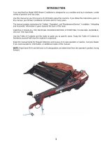
ASSEMBLY INSTRUCTIONS
The ALTERNA Mower Conditioner is shipped fully
assembled, except for the primary PTO shaft (1) and
the work wheels (2) which are unassembled to reduce
bulk. These loose components are attached to the
metallic drawbar support (3).
Drawbar support (3) has been specially designed for
improved ease of securing the unit in place and
facilitated handling and transporting for delivery.
1) Remove primary PTO shaft (1). Remove the
work wheels (2) and fit them on the work wheel
hubs.
Work wheels are to be fitted with the
valves on the outboard side of their
hubs.
Tighten wheel nuts to 15 daNm
(110 ft.lbs).
2) Remove drawbar support (3) as follows :
- Connect the two tractor draught arms to the
coupling yokes (4) by means of hitch pins (5).
- Lift the drawbar support (3) off the ground by
activating the tractor hydraulics.
- Remove pin (6) and lock parking stand (7) into
its vertical position using handle (8).
- Lower the tractor draught arms so that the
weight of the drawbar is supported by parking
stand (7).
- Remove the two pins (5) and take off the
drawbar support (3).
3) For reduced bulk, the left rear light support ele-
ment has not been installed in its final position.
Remove bolts (9), untighten bolt (10) and straighten
up the light support until its mounting hole lines up
with the tapped hole of the chassis. Reinstall bolts
(9) and torque both bolts to 2 - 3 daNm (15 - 22
ft.lbs).
NOTE: The ALTERNA 400 are supplied with one
right deflector (11) and one left deflector to
be mounted inside the hoods using the origi-
nal hardware (12) as shown on photo
opposite.
These deflectors enable forming even swaths
over the whole swath width when working in
slightly or moderately dense crops.
They must not be fitted for work in dense
or very dense crop.

- 12 -
ATTACHMENT TO THE TRACTOR
- Back the tractor up to the mower conditioner and
attach lower links (5) to the interior of the pivoting
yokes (4) with hitch pins (3). Secure the hitch pins
with linchpins (1).
For category 2 tractors use 28 mm hitch pins (3). For
category 3 tractors use 37 mm hitch pins (3) and
spacers (2).
- Activate the tractor hydraulics to completely raise
lower links (5).
- Fold up parking stand (6) and lock in place using
handle (7).
- Secure the tractor lower links laterally using check
chains or linkage stabilizer bars provided at the same
time making sure that the tractor PTO and machine
input shaft are lined up in the vertical plane.
Fitting the primary PTO shaft :
Connect the primary PTO shaft’s flanged yoke (8) to the
Gyrodine slip clutch. Secure in place using 6 self-
locking bolts (9) (M 12 x 25).
Tighten to a torque of 9 daNm (66 ft.lbs).
Make sure bolts are torqued to 9 daNm (66 ft.lbs).
To avoid accidents which could be serious, make
sure that the guards are always correctly in place
and secured with the safety chains. The safety
chain on the machine side must be attached on the
guard of the torque limiter. All worn or damaged
guards must be replaced immediately.

- 13 -
ATTACHMENT TO THE TRACTOR
Make sure the PTO shaft length is correct for the
tractor being used.
1) Activate the tractor hydraulics to line up the
tractor PTO and the machine input shaft in the
horizontal plane.
2) Slide the other half PTO shaft (without torque
limiter) onto the tractor PTO and align both half
PTO shafts side by side. If there is excessive
overlap, mark and shorten the hatched portions
of the transmission tube keeping a safety clear-
ance of 10 mm (0.5") between the ends of the
tubes and the yokes.
- Bevel and debur transmission
tubes. Remove all steel chips and
filings. Grease the inside of the
outer transmission tube.
- Shorten the guard tubes by the
same length as the transmission
tubes, as shown in the opposite
drawing.
- For your safety, there must be a
minimum tube overlap of 180 mm
(7") when the PTO shaft is in its
maximum extended position.
- Make sure the PTO shaft is con-
nected to the 1000 min-1 tractor
PTO.
3) All machine operations are controlled by the
tractor’s two double acting directional valves.
a) Connect hydraulic hoses (1) to the outlets of
the first directional valve, which will be re-
ferred to as DE1. Activating DE1 raises and
lowers the cutterbar.
b) Connect hydraulic hoses (2) to the outlets of
the second directional valve, which will be
referred to as DE2.
c) Carefully fit and cable the pre-cabled female
socket (5) (see electric lay-out, connections
and schematic).
d) Plug terminal (4) into the installed female
socket.
- Activating DE2 on its own sets the machine to
the right or to the left of the tractor.
- Activating DE2 and simultaneously pressing
thumb switch (3) raises and lowers transport
wheels.

- 14 -
DETACHING THE MACHINE
Machine must be parked with the weight of the
tongue resting on the parking stand.
When parking the machine :
- Fully raise the tractor lower links.
- Pull out lock handle (1) which secures parking
stand in the horizontal position (the parking stand
lowers on its own).
- Move the lower end of the parking stand back and
forth so that it automatically locks into the vertical
parking position.
- Lower the tractor lower links until yokes (2) are
relieved of the drawbar’s weight.
- Block the wheels with wedges if the area is not even
and level.
- Uncouple the tractor draught arms, the check
chains and the PTO shaft.
Safety chain (3) supports the primary PTO shaft
when the machine is disconnected from the tractor.
In this position the PTO shaft is not in contact with the
ground, thus avoiding deterioration due to dust and
dirt. Holder (4) provides effective protection to the
hydraulic quick couplers.
Place electric terminal (5) in its support and house
the remote control handle (6) with its terminal in the
storage box provided and close the lid.
Park the machine on level ground
when it is in the transport position.

- 15 -
Always ensure that nobody is near
the machine pivoting zone
(hatched area on the drawing
opposite) before and while chang-
ing the machine from the road
transport position to the work po-
sition.
Changing the machine from the road
transport position to the work
position.
Before starting this switch over, double check that
the tractor lower links are completely raised.
When operating on sloping ter-
rain and to avoid that the ma-
chine goes off course, activate
DE1 to extend the cylinders for
the work wheels so that they stay
as near to the ground as possible.
1) Activate DE2 until machine and drawbar are at a
90° angle to each other.
2) Activate DE1 to fully extend the cylinders for the
work wheels.
3) Press thumb switch and at the same time shift
DE2 in the same direction to raise the transport
wheels.
TRANSPORT TO WORK POSITION

- 16 -
4) Operate DE2 to position machine to the left or the
right side of the tractor.
5) Move slowly forward until the work wheels are
aligned in the same direction as the tractor wheels.
6) Operate DE1 to fully retract the work wheel
cylinders and lower the cutterbar onto the ground.
7) With the tractor’s hydraulic 3-point lift, position
the Girodyne head in order to set the hitch pins at
a distance of 700 mm/ 2’4" from the ground.
Hook one end of the check chains (R) to the hitch
brackets (C) by means of the shackles (S) and
attach the other side to the tractor’s top link yoke
by means of the top link hitch pin (A).
Lower the 3-point lift. The attachment is correct
when the underside face (I) of the tongue is
approximately horizontal and the lower hitch pins
are at a distance (H) of around 650 mm/2’2"
from the ground when the check chains (R ) are
taut.
The cutterbar must rest on the
ground before engaging the PTO.
Never mow in stony or rocky
grounds.
TRANSPORT TO WORK POSITION

- 17 -
Changing the machine from the work
position to the road transport position
It is advisable to first position machine to the right-hand
side of the tractor by shifting DE2.
1) Raise tractor lower links completely.
2) Activate DE1 to fully extend work wheel cylinders.
3) Press thumb switch and at the same time operate
DE2 to lower the transport wheels.
Note : Both transport wheel cylinders may not oper-
ate at the same speed. To assure that both
cylinders are fully extended, keep the valve
shifted for a few seconds after the front
transport wheel has closed up against its
stop. Then return DE2 to neutral.
4) Shift DE1 in the opposite direction to lower the
unit onto the transport wheels.
When operating on sloping ter-
rain and to avoid that the ma-
chine goes off course, keep the
work wheels as near to the ground
as possible.
WORK TO TRANSPORT POSITION
While changing the machine from
the work position ot the road trans-
port position:
- Stop tractor P.T.O. and wait for
rotating discs and rotor to stop.
- Always ensure that nobody is
near the machine pivoting zone
(hatched area on the drawing
opposite).

- 18 -
WORK TO TRANSPORT POSITION
5) Shift DE2 in the same direction to align the chassis
with cutting/ conditioning unit under the drawbar.
If the machine does not pivot when
shifting DE2, then the transport wheel
position sensor has not been closed
by the rear transport wheel. Repeat
procedure described in points 2 and
3 to eliminate the fault.
6) Close the swathboards completely in order to
reduce the machine’s transport width.
Before transporting the machine ensure that :
a) The cutting/conditioning unit is correctly locked
under the drawbar.
b) Work wheels are fully raised (cylinder rods com-
pletely retracted).
c) The 4 hydraulic hoses are unplugged and the
quick couplers are housed in their support.
d) The electric terminal is unplugged so that the
tractor batteries are not run down.
Always check that the rear lights
and indicators are clean and func-
tioning correctly before going on
the road.
Page is loading ...
Page is loading ...
Page is loading ...
Page is loading ...
Page is loading ...
Page is loading ...
Page is loading ...
Page is loading ...
Page is loading ...
Page is loading ...
Page is loading ...
Page is loading ...
Page is loading ...
Page is loading ...
Page is loading ...
Page is loading ...
Page is loading ...
Page is loading ...
Page is loading ...
Page is loading ...
Page is loading ...
Page is loading ...
Page is loading ...
Page is loading ...
Page is loading ...
Page is loading ...
Page is loading ...
Page is loading ...
Page is loading ...
Page is loading ...
Page is loading ...
Page is loading ...
-
 1
1
-
 2
2
-
 3
3
-
 4
4
-
 5
5
-
 6
6
-
 7
7
-
 8
8
-
 9
9
-
 10
10
-
 11
11
-
 12
12
-
 13
13
-
 14
14
-
 15
15
-
 16
16
-
 17
17
-
 18
18
-
 19
19
-
 20
20
-
 21
21
-
 22
22
-
 23
23
-
 24
24
-
 25
25
-
 26
26
-
 27
27
-
 28
28
-
 29
29
-
 30
30
-
 31
31
-
 32
32
-
 33
33
-
 34
34
-
 35
35
-
 36
36
-
 37
37
-
 38
38
-
 39
39
-
 40
40
-
 41
41
-
 42
42
-
 43
43
-
 44
44
-
 45
45
-
 46
46
-
 47
47
-
 48
48
-
 49
49
-
 50
50
-
 51
51
-
 52
52


KUHN ALTERNA 400 Assembly & Operators Manual
- Category
- Lawnmowers
- Type
- Assembly & Operators Manual
Ask a question and I''ll find the answer in the document
Finding information in a document is now easier with AI
Related papers
-
KUHN ALTERNA 400 User manual
-
-
-
-
-
-
-
-
Other documents
-
Krone AM 203CV,243CV,283CV Operating instructions
-
-
 Kellfri 35-FDM240 Owner's manual
-
-
 Kellfri 35-FDM160 Owner's manual
-
 PRONAR PDF290 Owner's manual
-
 MacDon 4000 User manual
-
Kubota DMC 8028 User manual
-
 MacDon R80 User manual
-
SaMASZ SAMBA 240 User manual


