


1
WARNING - to guard against injury, basic safety precautions should be
observed, including the following:
1. READ AND FOLLOW ALL SAFETY INSTRUCTIONS.
2. DANGER - To avoid possible electric shock, special care should be
taken since water is present near electrical equipment. Unless a
situation is encountered that is explicitly addressed by the provided
maintenance and troubleshooting sections, do not attempt repairs
yourself, refer to an authorized service facility.
3. Carefully examine the disinfection system after installation. It should
not be plugged in if there is water on parts not intended to be wet.
4. Do not operate the disinfection system if it has a damaged cord or
plug, if it is malfunctioning or if it is dropped or damaged in any
manner.
5. Always disconnect water flow and unplug the disinfection system
before performing cleaning or maintenance activities. Never yank the
cord to remove from an outlet grasp the wall plug and pull to
disconnect.
6. Do not use this disinfection system for other than intended use
(potable water applications). The use of attachments not approved,
recommended or sold by the manufacturer / distributor may cause an
unsafe condition.
7. Intended for indoor use only. Do not install this disinfection system
where it will be exposed to the weather or to temperatures below
freezing. Do not store this disinfection system where it will be exposed
to the weather. Do not store this disinfection system where it will be
exposed to temperatures below freezing unless all water has been
drained from it and the water supply has been disconnected.
8. Read and observe all the important notices and warnings on the water
disinfection system.
9. If an extension cord is necessary, a cord with a proper rating should be
used. A cord rated for less Amperes or Watts than the disinfection
system rating may overheat. Care should be taken to arrange the cord
so that it will not be tripped over or pulled.
10. SAVE THESE INSTRUCTIONS.
SAFETY INSTRUCTIONS:
Warning: The light given off by this unit can cause serious burns to
unprotected eyes and skin. Never look directly at a burning UV lamp.
When performing any work on the UV Disinfection System always unplug
the unit first. Never operate the UV system while the UV lamp is outside
of the UV Chamber.
Note: The UV lamp inside of the disinfection system is rated at an effective
life of approximately 9000 hours. To ensure continuous protection,
replace the UV lamp annually.

2
The Newly Revised ICE Ballast you have just purchased is an upgraded
version of the original ICE Ballast. This new ICE Ballast features an audible
lamp replacement reminder. After one year of lamp operation an alarm
will sound reminding you to replace your UV lamp in order to ensure
optimum UV disinfection levels.
The lamp replacement alarm function can be temporarily disabled for
seven days, by depressing the timer reset SWITCH/LED. After seven days
the alarm will sound again and may be delayed three more times for a
total of 28 days. After the fourth delay the lamp replacement alarm will
sound continuously until the lamp is changed and the alarm timer has
been reset (see below).
After installing the replacement UV lamp, apply power to the ballast while
holding the reset SWITCH/LED until you hear the three second beep, at
this time release the reset switch. Your timer has now been reset. In
approximately one year the alarm will sound again reminding you to
replace your UV lamp.
RESETTING THE REPLACEMENT LAMP ALARM TIMER:
ADDITIONAL FEATURES INCLUDED IN THE NEW ICE BALLAST:
• improved transient protection
• improved surge protection
• improved EMI filtering
• improved alarm circuity to warn of fuse failure
• improved lamp starting
• brownout protection
• conformal coated circuit board to assist with condensation
protection
• Patent US 6,274,988 B1
“NEW
“NEW FEA
FEATURES”
TURES”

3
Water quality is extremely important for the optimum performance of your
UV system. The following levels are recommended for installation:
• Iron: < 0.3 ppm (0.3 mg/L)
• Hardness*: < 7 gpg (120 mg/L)
• Turbidity: < 1 NTU
• Manganese: < 0.05 ppm (0.05 mg/L)
• Tannins: < 0.1 ppm (0.1 mg/L)
• UV Transmittance: > 75% (call factory for
recommendations on applications where UVT < 75%)
* Where total hardness is less than 7 gpg, the UV unit should
operate efficiently provided the quartz sleeve and/or sensor
probe is cleaned periodically. If total hardness is over 7 gpg,
the water should be softened.
If your water chemistry contains levels in excess of those mentioned above,
proper pre-treatment is recommended to correct these water problems
prior to the installation of your UV disinfection system. These water quality
parameters can be tested by your local dealer, or by most private analytical
laboratories. Proper pre-treatment is essential for the UV disinfection
system to operate as intended.
WATER CHEMISTRY:

4
INSTALLING YOUR UV DISINFECTION SYSTEM:
• CAUTION, electronic ballast must be connected to a grounded
receptacle and the lamp connector ground wire connected to the
stainless steel reactor chamber.
• The disinfection system is designed to be mounted horizontally or
vertically at the point-of-use or point-of-entry depending on the
specific flow rate of the unit.
Note: The ideal installation is vertical with the lamp connector
on top. This is to prevent water damage from occurring
on the lamp pins and lamp connector.
• The ballast should be mounted either above or beside the reactor
chamber. This will prevent moisture caused by condensation from
entering the ballast enclosure, causing a potential for ballast failure.
• The complete water system, including any pressure or hot water
tanks, must be sterilized before start up by flushing with chlorine
(household bleach) to destroy any residual contamination.
• For safety purposes, the disinfection system should be connected to a
ground fault interrupt circuit.
• The disinfection system is intended for indoor use only, do not install
disinfection system where it may be exposed to the weather.
• Install the disinfection system on cold water line only.
• If treating the entire house, install the disinfection system before any
branch lines.
• A 5 micron sediment filter must precede the disinfection system.
Ideally, the disinfection system should be the last treatment the water
receives before it reaches the faucet.
1. For shipping purposes, the UV lamp is shipped in a separate cardboard
tube. Carefully remove the UV lamp from the shipping tube being
careful not to touch the “glass” portion with your fingers. Insert the UV
lamp into the quartz sleeve and chamber making sure the connection
end is inserted last Mount the disinfection system to the wall with the
supplied clamp (1 clamp on all 1/2 and 1 gpm units and 2 clamps on all
2, 5, 8 and 12 gpm units). If required, a double-end clamp can be
purchased from your dealer to affix to an RO membrane.
2. If the disinfection system is to be hard plumbed, make sure you leave
enough clearance in front of the lamp connector to facilitate lamp
service (a length equal to the length of the unit should suffice).

5
3. Various connection methods can be used to connect the water source to
the disinfection system, however union type connectors are
recommended. The use of a flow restrictor device is strongly
recommended when installing your disinfection system in order that the
manufacturers recommended flow rate not be exceeded. These flow
restrictors are available from your dealer. In addition, the use of a by-pass
assembly is recommended for emergency use of untreated water when
your disinfection system is being serviced.
Note: When the UV unit is returned to service after being on by-
pass the complete water system must be sterilized once again
with chlorine (household bleach) to destroy any
contamination that may have entered the distribution system
while on by-pass. DO NOT SOLDER CONNECTIONS WHILE
ATTACHED TO THE DISINFECTION SYSTEM AS THIS COULD
DAMAGE THE O-RING SEALS.
4. Prior to connecting the power source, check all connections to ensure
that they are indeed secure, turn on water supply and check for any
leaks. If satisfied that there are no leaks, proceed with the following
steps.
5. To properly ground the stainless steel generating chamber, attach the
green wire coming from the power source to the grounding lug on the
UV chamber. Remove the green cap nut and slide the eyelet connector
onto the screw. Fasten the cap nut to the screw with a 5/16" wrench.
6. The power source provided with your disinfection system must be
located within (5) feet of an electrical outlet. DO NOT USE AN OUTLET
THAT CAN BE SWITCHED OFF (IE. A WASTE DISPOSAL OUTLET). Attach
the lamp connector to the UV lamp and press into the aluminum gland
nut. Plug the ballast into the outlet and ensure the POWER-ON LED is
illuminated. The audible ballast will enter a self test mode when power
is first applied to verify ballast operation.
Note: If ballast enters alarm condition, power must be removed for 30
seconds to allow ballast to reset.
Note:As the system requires time to reach its full operating capacity,
please allow the disinfection system to operate 3 - 5 minutes prior to using
the water from the unit. In addition, to clear any air or debris from the
system, open the faucet and allow water to run through the disinfection
system for 2 - 3 minutes (when using an RO application, run the water for
30 - 45 seconds).

6
OPERATING & MAINTENANCE INSTRUCTIONS:
NOTE: PRIOR TO PERFORMING ANY WORK ON THE
DISINFECTION SYSTEM, ALWAYS DISCONNECT THE POWER SUPPLY FIRST.
1. Regularly inspect your disinfection system to ensure that the UV lamp is
operating.
2. Replace the UV lamp with a new lamp after one year of continuous use
to ensure a high bacteria and virus kill rate. It should be noted that the
UV lamp should be ON continuously as repeatedly turning the lamp on
and off will severely shorten the lamp life and allow bacteria to pass
through without being affected by the UV.
3. To replace the UV lamp, first disconnect power. Disconnect the lamp
connector by carefully separating it from the gland nut (use the aid of a
slot screwdriver if required). Disconnect lamp connector from lamp and
carefully remove the UV lamp. Replace the new lamp being careful not
to touch the new UV lamp "glass" with your fingers as oils may impair
UV transmission. If contact does occur, clean lamp with alcohol and
reconnect lamp connector. Carefully replace lamp into stainless steel
cell. Press lamp connector into aluminum gland nut. Plug power source
into outlet. Verify POWER-ON LED is illuminated and ballast audible
start-up sequence operates.
4. If the water contains any hardness minerals (calcium or magnesium),
iron or manganese, the quartz sleeve will require periodic cleaning. To
remove the quartz sleeve, first remove the UV lamp as outlined in step
3. and follow the following steps:
a) Shut off water supply and drain all lines.
b) Remove the lowest connection on the disinfection system and
drain the UV chamber (use a small bucket under the unit to
prevent a spill).
c) Remove aluminum gland nuts from chamber. (do not allow
quartz sleeve to fall)
d) Carefully remove o-rings from the quartz sleeve. As the o-ring
may tend to adhere to the quartz sleeve, it is recommended to
replace the o-rings annually.
e) Clean the quartz sleeve with a cloth soaked in vinegar or some
other mild acid and then rinse.
f) Re-assemble the quartz sleeve in the UV chamber allowing the
sleeve to protrude an equal distance from both ends of the UV
chamber.
g) Wet the o-rings and slide onto each end of the quartz sleeve and
reassemble the gland nuts (hand tight is sufficient).
h) Re-tighten all connections, turn on water and check for leaks.
I) Re-install the UV lamp and lamp connector as per prior
instructions.
j) Plug in ballast and verify the POWER-ON LED is illuminated and
ballast power-up sequence operates.
Note: If the system is put on a temporary by-pass or if it becomes
contaminated after the disinfection system, it will be necessary to shock the system with
household bleach for a full 20 minutes before resuming the use of the water.

7
Manufacturer warrants the ultraviolet disinfection system hardware and
electrical systems to be free from defects in material and workmanship for a
period of five (5) years from the date of purchase by the original owner
(consumer) on a pro-rated basis. Manufacturer warrants the ultraviolet
lamps and to be free from defects in material and workmanship for a period
of one (1) year and the reactor chamber for a period of seven (7) years. The
warrantor will at its option and expense, either repair or replace such units
subject to the following conditions, exceptions, and exclusions. No other
warranties with respect to the units other than those expressly included in
this one year warranty, have been made by the Warrantor.
CONDITIONS, EXCEPTIONS, AND EXCLUSIONS
The foregoing limited Warranty is subject to the following terms and
conditions:
1.Water passed through the unit must fall within the following parameters:
a) Iron: < 0.3 ppm (0.3 mg/L)
b) Hardness*: < 7 gpg (120 mg/L)
c) Turbidity: < 1 NTU
d) Manganese: < 0.05 ppm (0.05 mg/L)
e) Tannins: < 0.1 ppm (0.3 mg/L)
f) UV Transmittance: > 75% (call factory for
recommendations on applications where UVT < 75%)
* Where total hardness is less than 7 gpg, the UV unit should operate
efficiently provided the quartz sleeve and/or sensor probe is cleaned
periodically. If total hardness is over 7 gpg, the water should be
softened.Warranty will be void, if the proper steps are not taken to
ensure that these impurities are not present.
2.This limited Warranty shall not apply to any unit which has been repaired
or altered by anyone other than the Warrantor or by a person authorized
by the Warrantor, nor to any units which have been subject to misuse,
neglect, or accident.
3.This limited Warranty runs exclusively to the original Consumer and with
respect to the original installation only.
4.WARRANTOR SHALL NOT BE LIABLE FOR ANY INCIDENTAL OR
CONSEQUENTIAL DAMAGES.
5.This limited Warranty excludes the cost of labour in removing any
defective unit or installing any replacement unit. This limited
Warranty applies only to a unit when returned to the Warrantor at the
owner’s expense and in accordance with shipping instructions
received from the Warrantor.
MANUFACTURER’SWARRANTY:

8
LAMPS
S212RL...................FOR SQ-PA UNIT
S287RL...................FOR S1Q-PA UNIT
S330RL...................FOR S2Q-PA UNIT
S463RL...................FOR S5Q-PA UNIT
S810RL...................FOR S8Q-PA UNIT
S36RL .....................FOR S12Q-PA UNIT
QUARTZ SLEEVES
QS-212...................FOR SQ-PA UNIT
QS-001...................FOR S1Q-PA UNIT
QS-330...................FOR S2Q-PA UNIT
QS-463...................FOR S5Q-PA UNIT
QS-810...................FOR S8Q-PA UNIT
QS-012...................FOR S12Q-PA UNIT
BALLASTS (IEC POWER CORDS SOLD SEPARATELY)
BA-ICE-1F .............FOR ALL (100-130V./50-60HZ.) UNITS
BA-ICE-2F .............FOR ALL (200-250V./50-60HZ.) UNITS
IEC POWER CORDS FOR BALLASTS
260010 ..................NORTH AMERICAN (NEMA 5-15P),
3-PRONG GROUNDED
260011 ..................CONTINENTAL EUROPEAN (CEE 7/7),
2 PIN WITH GROUND, “SCHUKO”
260012 ..................UK VERSION (BS 1363),
3 PRONG GROUNDED (5 AMP FUSE)
260013 ..................AUSTRALIAN VERSION (AS 3112),
3 PRONG GROUNDED
260019 ..................NO CONNECTOR, 3 WIRE,
BARE LEADS
O RINGS
OR-212...................FOR ALL UNITS
ALUMINUM GLAND NUTS
RN-001...................FOR ALL UNITS
PARTS BREAKDOWN:

9
SPECIFICATIONS SQ-PA S1Q-PA S2Q-PA S5Q-PA S8Q-PA S12Q-PA
Flow Rate 2 L/min
(1/2 gpm)
(0.12m3/Hr.)
4 L/min
(1 gpm)
(0.24m3/Hr.)
7.5 L/min
(2 gpm)
(0.45m3/Hr.)
19 L/min
(5 gpm)
(1.14m3/Hr.)
30 L/min
(8 gpm)
(1.80m3/Hr.)
45 L/min
(12 gpm)
(2.73m3/Hr.)
Length 28cm
(11”) 35.5cm
(14”) 47cm
(18.5”) 56cm
(22”) 90cm
(35”) 94cm
(37”)
Width 5.2cm
(2”) 6.5cm
(2.5”) 6.5cm
(2.5”) 6.5cm
(2.5”) 6.5cm
(2.5”) 8.9cm
(3.5”)
Height 5.2cm
(2”) 6.5cm
(2.5”) 6.5cm
(2.5”) 6.5cm
(2.5”) 6.5cm
(2.5”) 8.9cm
(3.5”)
Diameter 5.2cm
(2”) 6.5cm
(2.5”) 6.5cm
(2.5”) 6.5cm
(2.5”) 6.5cm
(2.5”) 8.9cm
(3.5”)
Shipping Weight 1.8kg
(4lbs.) 2.3kg
(5lbs.) 2.7kg
(6lbs.) 2.7kg
(6lbs.) 4.5kg
(10lbs.) 5.4kg
(12lbs.)
Voltage 100-130V./
50-60Hz1
100-130V./
50-60Hz1
100-130V./
50-60Hz1
100-130V./
50-60Hz1
100-130V./
50-60Hz1
100-130V./
50-60Hz1
Power
Consumption 12 16 19 26 39 42
Lamp
Watts 10 14 17 24 37 39
Maximum
Operating Pressure 8.62 bar
(125 psi) 8.62 bar
(125 psi) 8.62 bar
(125 psi) 8.62 bar
(125 psi) 8.62 bar
(125 psi) 8.62 bar
(125 psi)
Ambient
Temperature 2-40˚C
(36-104˚F) 2-40˚C
(36-104˚F) 2-40˚C
(36-104˚F) 2-40˚C
(36-104˚F) 2-40˚C
(36-104˚F) 2-40˚C
(36-104˚F)
Inlet/Outlet
Port Size 1/4”
MNPT 1/4”
MNPT 1/2”
MNPT 3/4”
MNPT 3/4”
MNPT
Combo
3/4” FNPT
1” MNPT
Visual
“Power-On” Yes Yes Yes Yes Yes Yes
Audible Lamp
Failure Yes Yes Yes Yes Yes Yes
Chamber
Material 304 S.S.2304 S.S.2 304 S.S.2 304 S.S.2 304 S.S.2 304 S.S.2
1. 200-250V./50-60 Hz., also available 2. 316L stainless steel available on request
SPECIFICATIONS:
Electrical Dimensions
-
 1
1
-
 2
2
-
 3
3
-
 4
4
-
 5
5
-
 6
6
-
 7
7
-
 8
8
-
 9
9
-
 10
10
-
 11
11
-
 12
12


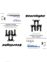
Sterilight S5Q-PQ Installation Instructions Manual
- Type
- Installation Instructions Manual
- This manual is also suitable for
Ask a question and I''ll find the answer in the document
Finding information in a document is now easier with AI
Other documents
-
WHOLE HOUSE UVF55FS User manual
-
ISPRING UVF55FS User manual
-
 Sterilite S12Q User manual
-
US Water Polaris UV Installation guide
-
Viqua VH200 Specification
-
Trojan VIQUA ISH520183 UV Lamp and Quartz Sleeve Operating instructions
-
WaterGroup Aqua Flo Filter Rack System Owner's manual
-
 Luminor LB6-061/2 Owner's manual
-
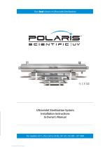 Polaris Scientific UV-12C Installation Instructions & Owner's Manual
-
Aquasana THD-UV-STD Installation guide


