Honeywell Lyric T6 Pro Wi-Fi Installation Instructions Manual
- Category
- Thermostats
- Type
- Installation Instructions Manual
Package Includes:
• T6 Pro Thermostat
• UWP™ Mounting System
• Honeywell Standard Installation
Adapter (J-box adapter)
• Honeywell Decorative Cover Plate –
Small; size 449/64 in x 449/64 in x
11/32 in (121 mm x 121 mm x 9 mm)
• Screws and anchors
• 2 AA Batteries
• Installation Instructions and User
Guide
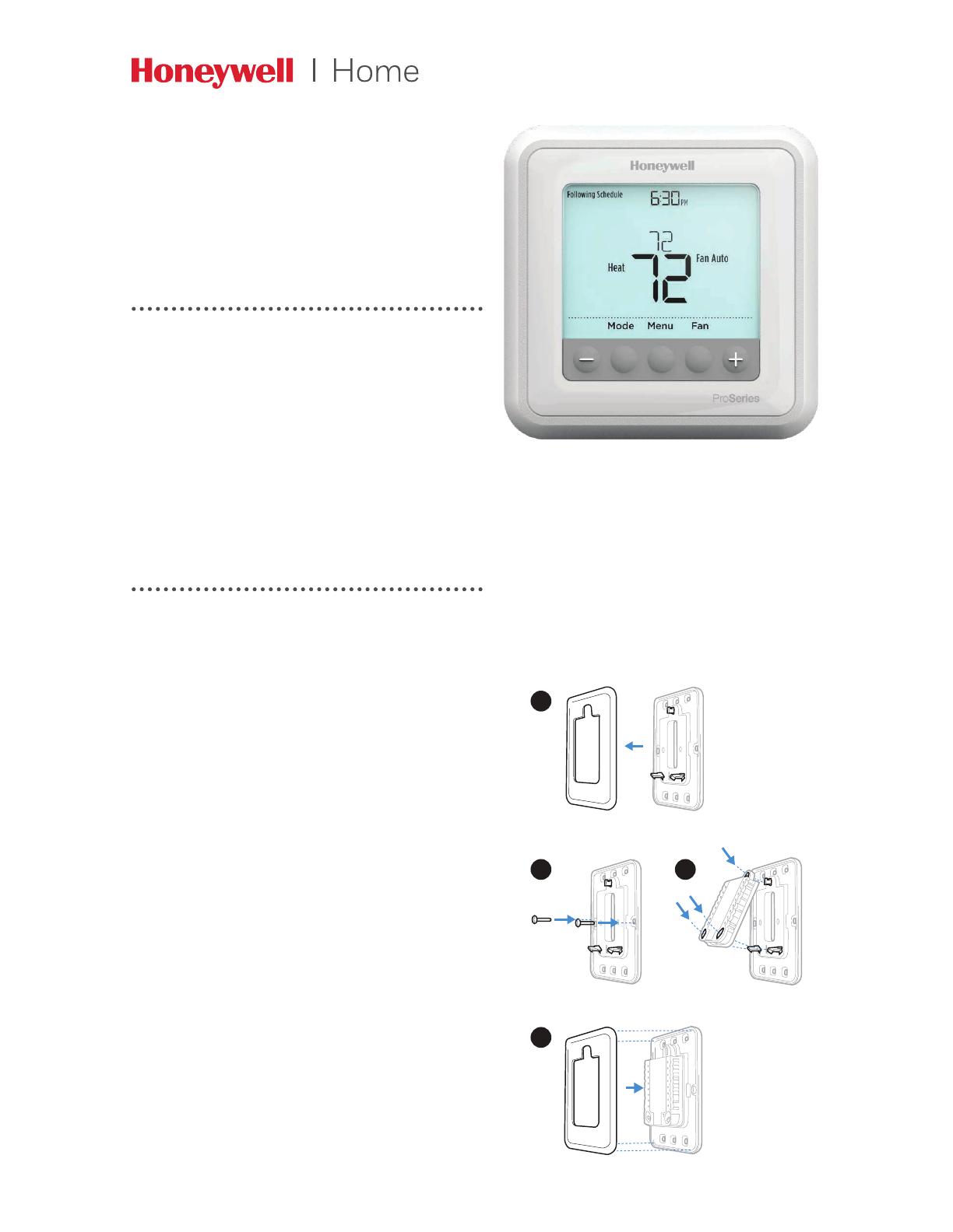
T6 Pro
Programmable Thermostat
Installation Instructions
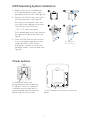
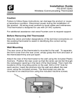
Optional Cover Plate installation
NOTE: If Optional Cover Plate is not
required, see “UWP Mounting System
installation” on next page.
Use the Optional Cover Plate when:
• Mounting the thermostat to an
electrical junction box
• Or when you need to cover paint gap
from old thermostat.
1. Separate the Junction Box Adapter
from the Cover Plate. See Figure 1.
2. Mount the Junction Box Adapter to
the wall or an electrical box using any
of the eight screw holes. Insert and
tighten mounting screws supplied with
Cover Plate Kit. Do not overtighten. See
Figure 2. Make sure the Adapter Plate
is level.
3. Attach the UWP by hanging it on the
top hook of the Junction Box Adapter
and then snapping the bottom of the
UWP in place. See Figure 3.
4. Snap the Cover Plate onto the Junction
Box Adapter. See Figure 4.
Use 2x
supplied
screws #6
5/8”
4
3
2
1
2
S
S
Y2
U
U
G
C
Y
A
Rc
W
K
W2
R
L/A
O/B
AUX
E
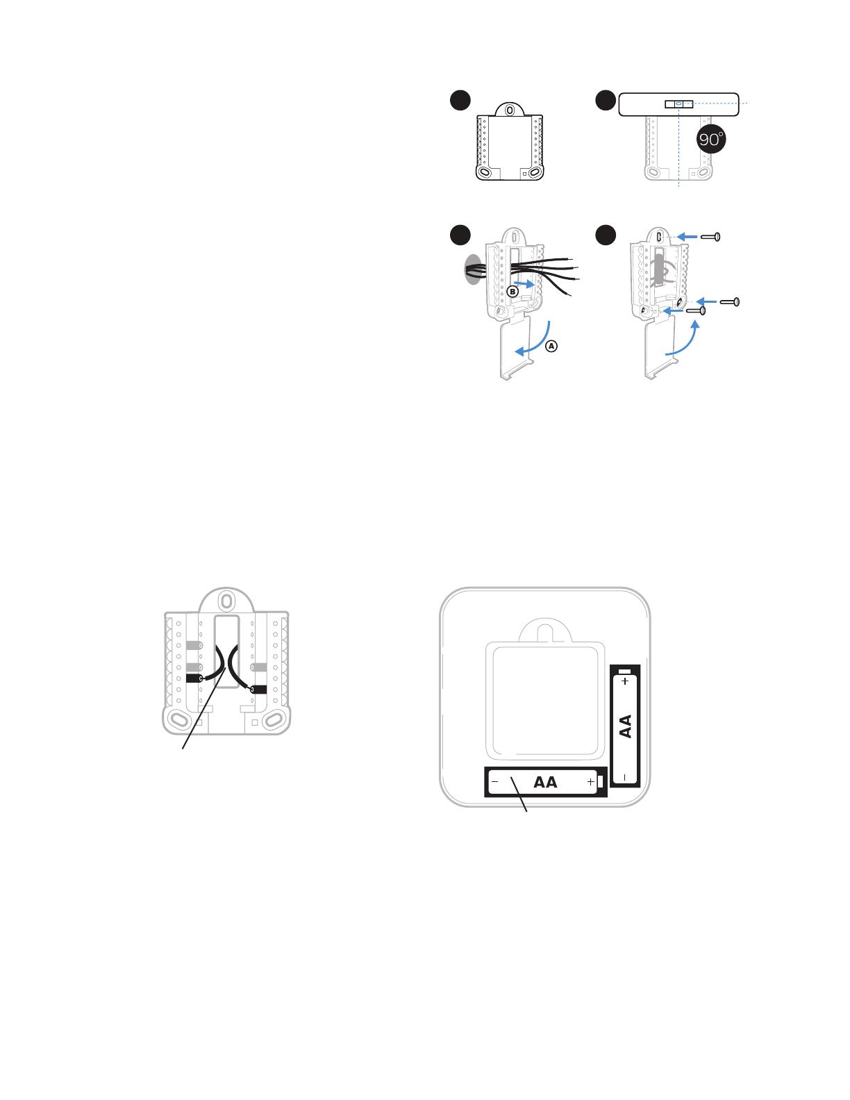
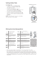
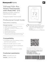
Power options
Insert R and C wires into
designated terminals for primary
AC power (C terminal is optional
if batteries are installed, but it is
recommended). Remove wires by
depressing the terminal tabs.
Insert AA batteries for primary or backup
power.
UWP Mounting System installation
Use 3x supplied
screws #8 11/2”
5. Before starting, turn the power off
at the breaker box or switch. Open
package to find the UWP. See Figure 5.
6. Position the UWP on wall. Level and
mark hole positions. See Figure 6.
Drill holes at marked positions, and
then lightly tap supplied wall anchors
into the wall using a hammer.
‒Drill 7/32” holes for drywall.
7. Pull the door open and insert the wires
through wiring hole of the UWP. See
Figure 7.
8. Place the UWP over the wall anchors.
Insert and tighten mounting screws
supplied with the UWP. Do not
overtighten. Tighten until the UWP
no longer moves. Close the door. See
Figure 8.
8
5
6
7
3
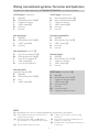
Wiring terminal designations
SInput for wired indoor
or outdoor sensors
(TH6320U and
TH6220U only)
L/A
- A
Heat Pump fault input
(Common (C) wire required
for LA/A)
SO/B Changeover valve
YCompressor contactor
(stage 1)
AUX -
W2
Auxiliary heat relay
Heat relay (stage 2)
Y2 Compressor contactor
(stage 2) EEmergency Heat relay
GFan Relay WHeat relay (stage 1)
C
24VAC common. For 2
transformer systems,
use common wire from
cooling transformer.
KConnect to K on Wire Saver
Module**
U
Unused
R24VAC power from heating
transformer*
URc 24VAC power from cooling
transformer*
Note: Not all
terminals may be
used, depending
on the system
type that is being
wired. The most
commonly used
terminals are
shaded.
* Terminal can be jumped using Slider Tab. See “Setting Slider Tabs” above.
** The THP9045A1023 Wire Saver Module is used on heat/cool systems when you
only have four wires at the thermostat, and you need a fifth wire for a common wire.
Use the K terminal in place of the Y and G terminals on conventional or heat pump
systems to provide control of the fan and the compressor through a single wire—the
unused wire then becomes your common wire. See THP9045 instructions for more
information.
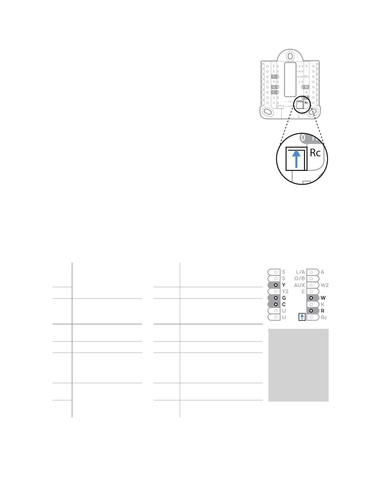
Set R Slider Tab.
• Use built-in jumper (R Slider Tab)
to differentiate between one or two
transformer systems.
• If there is only one R wire, and it is
connected to the R, Rc, or RH terminal, set
the slider to the up position (1 wire).
• If there is one wire connected to the R
terminal and one wire connected to the Rc
terminal, set the slider to the down position
(2 wires).
NOTE: Slider Tabs for U terminals should be
left in place for T6 Pro models.
Setting Slider Tabs
R/Rc slider tab
UWP Mounting System

4
1H/1C System (1 transformer)
R Power [1]
Rc [R+Rc joined by Slider Tab] [2]
Y Compressor contactor
C 24VAC common [3]
W Heat relay
G Fan relay
Heat-only System
R Power [1]
Rc [R+Rc joined by Slider Tab] [2]
C 24VAC common [3]
W Heat relay
Heat-only System (Series 20) [5]
R Series 20 valve terminal “R” [1]
Rc [R+Rc joined by Slider Tab] [2]
Y Series 20 valve terminal “W”
C 24VAC common [3]
W Series 20 valve terminal “B”
Heat-only System
(power open zone valve) [5]
R Power [1]
Rc [R+Rc joined by Slider Tab] [2]
W Valve
C 24VAC common [3]
1H/1C System (2 transformers)
R Power (heating transformer) [1]
Rc Power (cooling transformer) [1]
Y Compressor contactor
C 24VAC common [3, 4]
W Heat relay
G Fan relay
Heat-only System with Fan
R Power [1]
Rc [R+Rc joined by Slider Tab] [2]
C 24VAC common [3]
W Heat relay
G Fan relay
Cool-only System
R Power [1]
Rc [R+Rc joined by Slider Tab] [2]
Y Compressor contactor
C 24VAC common [3]
G Fan relay
2H/2C System (1 transformer) [6]
R Power [1]
Rc [R+Rc joined by Slider Tab] [2]
Y Compressor contactor (stage 1)
C 24VAC common [3]
W Heat relay (stage 1)
G Fan relay
W2 Heat relay (stage 2)
Y2 Compressor contactor (stage 2)
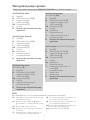
Wiring conventional systems: forced air and hydronics
Shaded areas below apply only to TH6320U/TH6220U or as otherwise noted.
NOTES
Wire specifications: Use 18 to 22-gauge thermostat wire. Shielded cable is not required.
[1] Power supply. Provide disconnect means and over-
load protection as required.
[2] Move RSlider Tab on UWP to the R setting. For
more information, see “Setting Slider Tabs” on page
3
[3] Optional 24VAC common connection.
[4] Common connection must come from cooling
transformer.
[5] In ISU set Heat system type to Radiant Heat. Set
number of cool stages to 0.
[6] In Installer Setup, set system type to 2Heat/2Cool
Conventional.

5
1H/1C Heat Pump System
R Power [1]
Rc [R+Rc joined by Slider Tab] [2]
Y Compressor contactor
C 24VAC common [3]
O/B Changeover valve [7]
G Fan relay
W Do not use this terminal for heat pump
applications!
2H/1C Heat Pump System [8]
R Power [1]
Rc [R+Rc joined by Slider Tab] [2]
Y Compressor contactor
C 24VAC common [3]
O/B Changeover valve [7]
G Fan relay
Aux Auxiliary heat
E Emergency heat relay
L Heat pump fault input
W Do not use this terminal for heat pump
applications!
2H/2C Heat Pump System
(TH6320U only) [9]
R Power [1]
Rc [R+Rc joined by Slider Tab] [2]
Y Compressor contactor (stage 1)
C 24VAC common [3]
O/B Changeover valve [7]
G Fan relay
Y2 Compressor contactor (stage 2)
L Heat pump fault input
W Do not use this terminal for heat pump
applications!
3H/2C Heat Pump System
(TH6320U only) [10]
R Power [1]
Rc [R+Rc joined by Slider Tab] [2]
Y Compressor contactor (stage 1)
C 24VAC common [3]
O/B Changeover valve [7]
G Fan relay
Aux Auxiliary heat
E Emergency heat relay
Y2 Compressor contactor (stage 2)
L Heat pump fault input
W Do not use this terminal for heat pump
applications!
Dual Fuel System (TH6320U / TH6220U only)
R Power [1]
Rc [R+Rc joined by Slider Tab] [2]
Y Compressor contactor (stage 1)
C 24VAC common [3]
O/B Changeover valve [7]
G Fan relay
Aux Auxiliary heat
E Emergency heat relay
Y2 Compressor contactor (stage 2 - if
needed) [11]
L Heat pump fault input
S Outdoor sensor
S Outdoor sensor
W Do not use this terminal for heat pump
applications!
Wiring heat pump systems
Shaded areas below apply only to TH6320U/TH6220U or as otherwise noted.
NOTES
Wire specifications: Use 18 to 22-gauge thermostat wire. Shielded cable is not required.
[1] Power supply. Provide disconnect means and over-
load protection as required.
[2] Move RSlider Tab on UWP to the R setting. For
more information, see “Setting Slider Tabs” on page
3
[3] Optional 24VAC common connection.
[6] In Installer Setup, set system type to 2Heat/2Cool
Conventional.
[7] In Installer Setup, set changeover valve to O (for
cool changeover) or B (for heat changeover).
[8] In ISU set Heat system type to Heat pump. 1 com-
pressor and 1 stage of backup heat.
[9] In ISU set Heat system type to Heat pump. 2 com-
pressors and 0 stage of backup heat.
[10] In ISU set Heat system type to Heat pump. 2 com-
pressors and 1 stage of backup heat.
[11] Dual fuel with Y2 only for TH6320U.

6
Thermostat mounting
1. Push excess wire back into the wall
opening.
2. Close the UWP door. It should remain
closed without bulging.
3. Align the UWP with the thermostat, and
push gently until the thermostat snaps in
place.
4. Turn the power on at the breaker box or
switch.
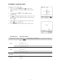
Set the time and date
Time
1 Press Menu on your thermostat.
2 Press or to go to TIME. Press Select.
3 Press or to choose between 12 or 24 hour.
Press Select.
4 Use or to adjust the hour. Press Select.
5 Use or to adjust the minutes. Press Select
to exit Time menu.
Date
1 If previously setting time, continue to Step
2. If at the Home screen, press Menu on your
thermostat.
2 Press or to go to DATE. Press Select.
3 Use or to adjust year. Press Select.
4 Use the or to adjust month. Press Select.
5 Use the or to adjust day. Press Select to
save and exit Date menu.
7
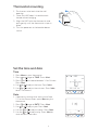
Fan operation settings
1 Press the Fan button to cycle to the next
available Fan mode.
2 Cycle through the modes until the required
Fan mode is displayed and leave it to
activate.
NOTE: Available Fan modes vary with system
settings.
Fan modes:
‒Auto: Fan runs only when the heating or
cooling system is on.
‒On: Fan is always on.
‒Circ: Fan runs randomly about 33% of
the time.
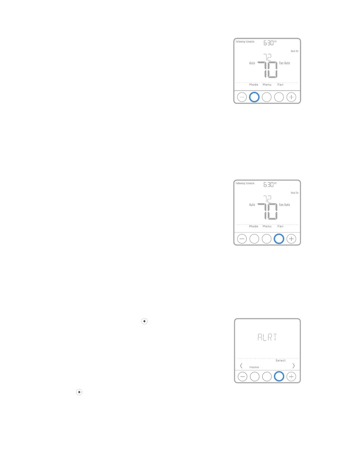
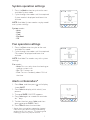
System operation settings
1 Press the Mode button to cycle to the next
available System mode.
2 Cycle through the modes until the required
System mode is displayed and leave it to
activate.
NOTE: Available System modes vary by model
and system settings.
System modes:
‒Auto
‒Heat
‒Cool
‒Em Heat
‒Off
Alerts or Reminders*
1 Press Menu, and then press until display
shows ALRT.
2 Press Select to display which alert(s) are
present.
3 The word SNZE (SNOOZE) appears.
4 Press Select again to snooze the reminder
for 7 days.
5 To clear the alert, press Select, and then
press to go to CLER (Clear).
6 Press Select to clear the reminder.
* Some alerts cannot be snoozed or cleared.
Please call your local heating and cooling
professional if this occurs. The heating and
cooling system may require service.
8
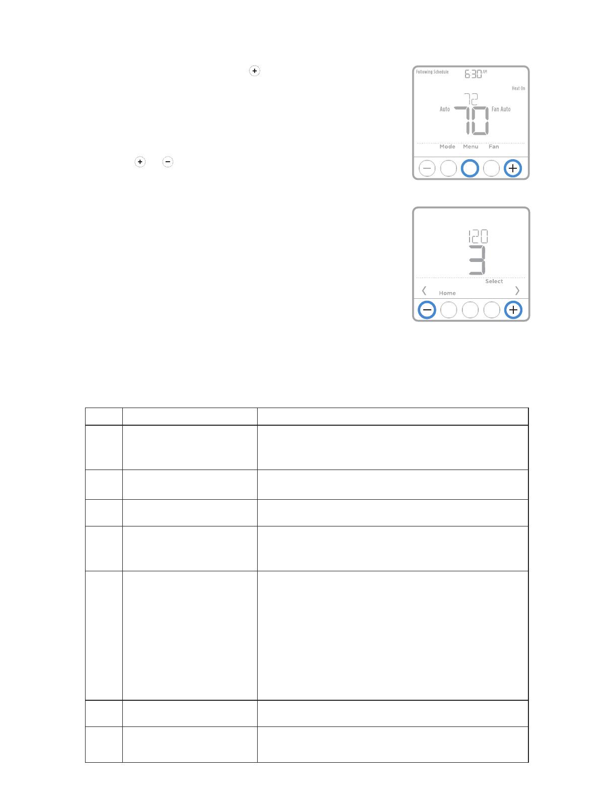
1 Press and hold CENTER and buttons for
approximately 3 seconds to enter advanced
menu.
2 Press Select to enter ISU.
3 Press Select to cycle through menu setup
options.
4 Press or to change values or select
from available options.
5 Press Select and confirm your settings or
press Back to ignore changes and return
to ISU menu screen to continue editing
another setup option.
6 To finish setup process and save your
setting, press Home and return to Home
screen.
NOTE: A complete list of all setup (ISU)
parameters and options starts below and
continues through page 10.
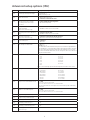
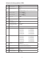
Installer setup (ISU)
Advanced setup options (ISU)
NOTE: Depending on system settings, not all options may be available.
# ISU ISU Name ISU Options (factory default in bold)
120 Scheduling Options 0 = NonProgrammable
2 = 52 Programmable
3 = 511 Programmable
4 = 7Day Programmable
125 Temperature Indication Scale 0 = Fahrenheit
1 = Celsius
130 Outdoor Sensor
(TH6320U / TH6220U only) 0 = None
1 = Wired Outdoor Sensor
200 Heating System Type 1 = Conventional Forced Air Heat
2 = Heat Pump
3 = Radiant Heat
5 = None (Cool Only)
205 Heating Equipment Type Conventional Forced Air Heat:
1 = Standard Efficiency Gas Forced Air
2 = High Efficiency Gas Forced Air
3 = Oil Forced Air
4 = Electric Forced Air
5 = Hot Water Fan Coil
Heat Pump:
7 = Air to Air Heat Pump
8 = Geothermal Heat Pump
Radiant Heat:
9 = Hot Water Radiant Heat
12 = Steam
218 Reversing Valve O/B 0 = O (O/B in Cool)
1 = B (O/B in Heat)
220 Cool Stages / Compressor Stages
200=Conv / 200=HP 0, 1, 2
Note: Only 1 compressor stage available on TH6210U model. Only 1 compressor
stage available on TH6220U model if configured for heat pump.

9
# ISU ISU Name ISU Options (factory default in bold)
221 Heat Stages / Backup Heat Stages Heat Stages: 1, 2
Backup Heat Stages: 0, 1
230 Fan Control in Heat 1 = Equipment Controls Fan
2 = Thermostat Controls Fan
253 Aux/E terminal control (Fixed to
“0” setting on all models except
TH6320U)
0 = Drive both Aux & E together
1 = Aux and E independent
255 Backup Heat Source
(Heat Pump Only)
(TH6320U / TH6220U only)
1 = Electric Forced Air
2 = Gas/Oil Forced Air (or Fossil Forced Air)
256 Emergency Heat Source (TH6320U
only) 1 = Electric Forced Air
2 = Gas/Oil Forced Air (or Fossil Forced Air)
260 External Fossil Fuel Kit
(TH6320U / TH6220U only) 0 = Thermostat Controls Backup Heat
1 = External Fossil Fuel Kit Controls Backup Heat
300 System Changeover 0 = Manual
1 = Automatic
303 Auto Changeover Differential 0 °F to 5 °F
0.0 °C to 2.5 °C
Note: Differential is NOT deadband. Honeywell uses an advanced algorithm that
fixes deadband at 0 °F. The differential setting is the minimum number of degrees
from set-point needed to switch from the last mode running (heat or cool) to the
opposite mode when the thermostat is in auto-changeover. This is more advanced
than previous thermostats.
340 Backup Heat Droop 0 = Comfort
2 = 2 °F
3 = 3 °F
4 = 4 °F
5 = 5 °F
6 = 6 °F
7 = 7 °F
8 = 8 °F
9 = 9 °F
10 = 10 °F
11 = 11 °F
12 = 12 °F
13 = 13 °F
14 = 14 °F
15 = 15 °F
Note: 0 (comfort) setting only available if backup heat (ISU 255) is set to electric.
350 Upstage Timer for Backup Heat 0 = Off
1 = 30 minutes
2 = 45 minutes
3 = 60 minutes
4 = 75 minutes
5 = 90 minutes
6 = 2 hours
7 = 3 hours
8 = 4 hours
9 = 5 hours
10 = 6 hours
11 = 8 hours
12 = 10 hours
13 = 12 hours
14 = 14 hours
16 = 16 hours
355 Compressor Lockout / Balance Point -- = Off
5 °F to 60 °F (in 5 °F increments)
15.0 °C to 15.5 °C (in 2.5 °C or 3.0 °C increments)
Note: Use a wired sensor to set compressor lockout / balance point on TH6320U
/ TH6220U.
356 Outdoor Lockout Backup Heat -- = Off
5 °F to 65 °F (in 5 °F increments)
15.0 °C to 18.5 °C (in 2.5 °C or 3.0 °C increments)
365 Compressor Cycle Rate (Stage 1) 1 - 6
366 Compressor Cycle Rate (Stage 1) 1 - 6
370 Heating Cycle Rate (Stage 1) 1 - 12
371 Heating Cycle Rate (Stage 2) 1 - 12
375 Heating Cycle Rate Auxiliary Heat 1 - 12
378 Heating Cycle Rate Emergency Heat
(TH6320U only) 1 - 12
Advanced setup options (ISU)

10
# ISU ISU Name ISU Options (factory default in bold)
387 Compressor Protection 0 = Off
1 - 5 minutes
425 Adaptive Intelligent Recovery 0 = No
1 = Yes
Note: Adaptive Intelligent Recovery (AIR) is a comfort setting. Heating or cooling
equipment will turn on earlier, ensuring the indoor temperature will match the
setpoint at the scheduled time.
430 Minimum Cool Setpoint 50 °F to 99 °F (50 °F)
10.0 °C to 37.0 °C (10.0 °C)
431 Maximum Heat Setpoint 40 °F to 90 °F (90 °F)
4.5 °C to 32.0 °C (32.0 °C)
435 Keypad Lockout 0 = None
1 = Partial
2 = Full
500 Is Indoor Temperature Sensor
WIRED to your system? (TH6320U /
TH6220U only)
0 = No
1 = Yes
515 Indoor Sensor type
(TH6320U / TH6220U only) 0 = 10k
1 = 20k
520 Which Sensors will be used for
TEMPERATURE Control? (Multiple
Sensors are Averaged) TH6320U /
TH6220U only)
1 = Thermostat Only
2 = Wired Only
3 = Average
702 Number of Air Filters 0 - 2
711 Air Filter 1 Replacement Reminder 0 = Off
1 = 10 Run Time Days
2 = 20 Run Time Days
3 = 30 Run Time Days
4 = 45 Run Time Days
5 = 60 Run Time Days
6 = 90 Run Time Days
7 = 120 Run Time Days
8 = 150 Run Time Days
9 = 30 Calendar Days
10 = 45 Calendar Days
11 = 60 Calendar Days
12 = 75 Calendar Days
13 = 3 Calendar Months
14 = 4 Calendar Months
15 = 5 Calendar Months
16 = 6 Calendar Months
17 = 9 Calendar Months
18 = 12 Calendar Months
19 = 15 Calendar Months
712 Air Filter 2 Replacement Reminder 0 = Off
1 = 10 Run Time Days
2 = 20 Run Time Days
3 = 30 Run Time Days
4 = 45 Run Time Days
5 = 60 Run Time Days
6= 90 Run Time Days
7 = 120 Run Time Days
8 = 150 Run Time Days
9 = 30 Calendar Days
10 = 45 Calendar Days
11 = 60 Calendar Days
12 = 75 Calendar Days
13 = 3 Calendar Months
14 = 4 Calendar Months
15 = 5 Calendar Months
16 = 6 Calendar Months
17 = 9 Calendar Months
18 = 12 Calendar Months
19 = 15 Calendar Months
1400 Backlighting 0 = On Demand
1 = Continuous
Note: Common wire needed for continuous.
1401 Backlight brightness 1 - 5
Note: Only displayed if continuous backlight selected.
1410 Clock Format 12 / 24
1415 Daylight Saving Time 0 = Off
1 = On
1420 Temperature Display Offset 3 to 3F (0)
1.5 to 1.5C (0)
Advanced setup options (ISU)
11
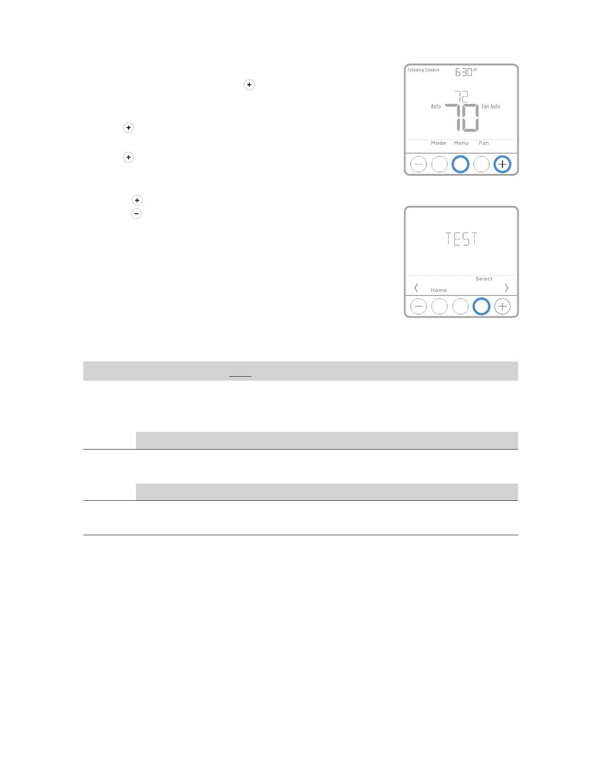
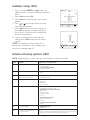
Installer system test
To perform a System Test:
1 Press and hold CENTER and buttons for
approximately 3 seconds to enter advanced
menu.
2 Use to go to TEST. Press Select to enter
System Test.
3 Use to change between Heat, Cool, Fan, Em
Heat, or Ver (thermostat version information).
Press Select.
4 Press to turn stages on one at a time, and
press to turn them off.
5 Use the Home button to exit the System Test.
System test System status
Shaded areas below apply only to TH6320U/TH6220U or as otherwise noted.
Heat
0All Off
1Heat Stage 1 on
2Heat Stage 2 also on
3Heat Stage 3 also on
Cool
0All Off
1Cool Stage 1 on
2Cool Stage 2 also on
Em Heat 0All Off
1Em Heat on
Fan 0Fan Off
1Fan On

12
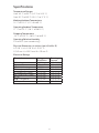
Specifications
Temperature Ranges
Heat: 40 °F to 90 °F (4.5 °C to 32.0 °C)
Cool: 50 °F to 99 °F (10.0 °C to 37.0 °C)
Working Ambient Temperature
32 °F to 120 °F (0 C° to 48.9 °C)
Operating Ambient Temperature
37 °F to 102 °F (2.8 °C to 38.9 °C)
Shipping Temperature
20 °F to 120 °F (28.9 °C to 48.9 °C)
Operating Relative Humidity
5% to 90% (non-condensing)
Physical Dimensions in inches (mm) (H x W x D)
41/16” H x 41/16” W x 15/32” D
103.5 mm H x 103.5 mm W x 29 mm D
Electrical Ratings
Terminal Voltage
(50/60Hz) Running
Current
W Heating 2030 Vac 0.021.0 A
(Powerpile) 750 mV DC 100 mA DC
W2 (Aux) Heating 2030 Vac 0.021.0 A
E Emergency Heat 2030 Vac 0.020.5 A
Y Compressor Stage 1 2030 Vac 0.021.0 A
Y2 Compressor Stage 2 2030 Vac 0.021.0 A
G Fan 2030 Vac 0.020.5 A
O/B Changeover 2030 Vac 0.020.5 A
L/A Input 2030 Vac 0.020.5 A

13
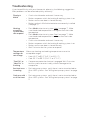
Troubleshooting
If you have difficulty with your thermostat, please try the following suggestions.
Most problems can be corrected quickly and easily.
Display is
blank • Check circuit breaker and reset if necessary.
• Make sure power switch for heating & cooling system is on.
• Make sure furnace door is closed securely.
• Make sure fresh AA alkaline batteries are correctly installed
(see page 2).
Heating
or cooling
system does
not respond
• Press Mode button to set system Heat (see page 7). Make
sure the desired temperature is set higher than the inside
temperature.
• Press Mode button to set system Cool (see page 7). Make
sure the desired temperature is set lower than the inside
temperature.
• Check circuit breaker and reset if necessary.
• Make sure power switch for heating & cooling system is on.
• Make sure furnace door is closed securely.
• Wait 5 minutes for the system to respond.
Temperature
settings do
not change
Make sure heating and cooling temperatures are set to
acceptable ranges:
• Heat: 40 °F to 90 °F (4.5 °C to 32.0 °C)
• Cool: 50 °F to 99 °F (10.0 °C to 37.0 °C)
“Cool On” or
“Heat On” is
flashing
• Compressor protection feature is engaged. Wait 5 minutes
for the system to restart safely, without damage to the
compressor.
Aux heat runs
in cooling • For heat pump systems, verify there is not a wire attached to
W on UWP systems. See “Wiring heat pump systems” on page
5.
Cool runs with
a call for heat • For heat pump systems, verify there is not a wire attached to
W on UWP systems. See “Wiring heat pump systems” on page
5.
Home and Building Technologies
In the U.S.:
Honeywell
715 Peachtree Street NE
Atlanta, GA 30308
customer.honeywell.com
® U.S. Registered Trademark.
© 2018 Honeywell International Inc.
33-00181EFS—11 M.S. Rev. 02-18
Printed in U.S.A.
33-00181EFS-11
For assistance with this product, please visit
customer.honeywell.com.
Or call Honeywell Customer Care toll-free at
18004681502.
Customer assistance
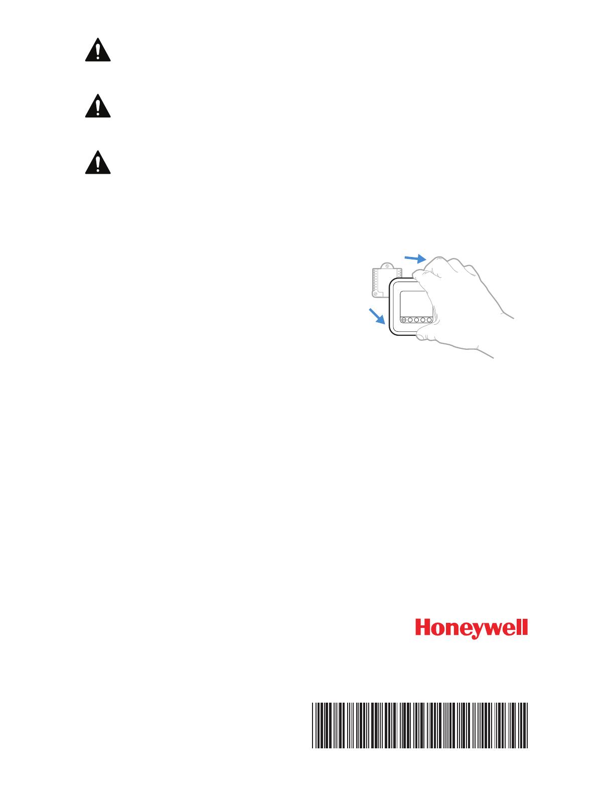
Pull to remove the thermostat
from the UWP.
+
CAUTION: MERCURY NOTICE
If this product is replacing a control that contains mercury in a sealed
tube, do not place the old control in the trash. Contact your local waste
management authority for instructions regarding recycling and proper
disposal.
CAUTION: EQUIPMENT DAMAGE HAZARD
Compressor protection is bypassed during testing. To prevent equipment
damage, avoid cycling the compressor quickly.
CAUTION: ELECTRICAL HAZARD
Can cause electrical shock or equipment damage. Disconnect power before
beginning installation.
-
 1
1
-
 2
2
-
 3
3
-
 4
4
-
 5
5
-
 6
6
-
 7
7
-
 8
8
-
 9
9
-
 10
10
-
 11
11
-
 12
12
-
 13
13
-
 14
14


Honeywell Lyric T6 Pro Wi-Fi Installation Instructions Manual
- Category
- Thermostats
- Type
- Installation Instructions Manual
Ask a question and I''ll find the answer in the document
Finding information in a document is now easier with AI
Related papers
-
Honeywell T6 Pro TH6320U2008 Owner's manual
-
Honeywell TH6210U2001 Installation guide
-
Honeywell T6 Owner's manual
-
Honeywell TH8320ZW Installation guide
-
Honeywell RTH7500 Installation guide
-
-
Honeywell T1 Pro Installation Instructions Manual
-
resideo RCHT8612WF20052PK Operating instructions
-
-
Other documents
-
 Founten FS-STAT-32AC Installation guide
-
 Honeywell Home THX321WFS2001W Installation guide
-
Honeywell Home T3 Pro Installation Instructions Manual
-
MRCOOL MST03 Installation guide
-
 Honeywell Home RTH7560E User manual
-
Trane Charge Assist User manual
-
Trane TCONT402AN32DA Installer's Manual
-
-
Robertshaw PerfectSense PS4000 and PS5000 Touchscreen Programmable Thermostat User manual
-
Avision DF-0510 Installation guide


