Honeywell RM7800L1087, RM7840G1022, RM7840L1075, EC7840L1014, RM7800L2087, RM7840G2022, RM7840GL2075, EC7840L2014 Relay Modules Operating instructions
- Category
- Fire protection
- Type
- Operating instructions

INSTALLATION INSTRUCTIONS
32-00142-01
SIL3
Capable
RM7800L1087, RM7840G1022, RM7840L1075, EC7840L1014
RM7800L2087, RM7840G2022, RM7840GL2075, EC7840L2014
Relay Modules with Valve Proving
APPLICATION
The Honeywell RM7800L/40G,L and EC7840L Relay
Modules are microprocessor-based integrated burner
controls for automatically fired gas, oil, or combination fuel
single burner applications. The RM7800L/40G,L and
EC7840L Relay Modules are used for UL/CSA Modulating
and FM/IRI Modulating burner applications. The
RM7800L/40G,L, EC7840L
system consists of a Relay
Module. Keyboard Display Modules (standard with
RM7800), Dust Cover (standard with RM7840/EC7840L),
Subbase, Amplifier, and Purge Card. Options include DATA
CONTROLBUS MODULE™, Remote Display Mounting,
First-Out Expanded Annunciator and Modbus™
communications capable.
Functions provided by the RM7800L/40G,L, EC7840L
include automatic burner sequencing, flame supervision,
system status indication, system or self-diagnostics and
troubleshooting.
Using the S7800A2142 Keyboard Display (standard on
RM7800L2087) the following features can be set up:
• Post Purge time—Up to 60 minutes—Device shipped
with 15 seconds Post purge.
• Valve Proving features including:
— VPS test time
— When (Never, Before, After, Split or Both)
• See S7800A1142 Instructions (65-0288), also see
S7800A2142 Instructions. Series 5 can be
programmed for Modbus communication.
At commissioning time, the Valve Proving System may be
scheduled to occur at one of five different times:
• Never—Device default as received—Valve proving
does not occur.
• Before—Valve proving before run concurrent with Pre-
Purge.
• After—Valve proving occurs after the Run state,
before the device goes to Standby (Concurrent with
Post-Purge, if selected.)
• Both—Valve proving occurs at both times Before and
After, noted above.
• Split—The main valve 2 (MV2) (high pressure) seat
test is performed at the Before time and the main
valve 1 (MV1) (low pressure) seat test is performed
during the After time.
The following assumptions apply when using the
RM7840G,L, RM7800L, EC7840L:
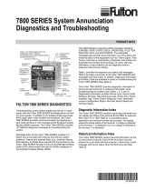
Fig. 1. The valve proving system.
MV1—Wired to terminal 9. It is located in the most
upstream position of the main gas valve train.
VPS—Valve Proving Switch: Setpoint at 1/2 of Main Valve
inlet pressure.
MV2—Wired to terminal 21. It is the main valve located
closest to the burner.
The PII—Pre-Ignition Interlock (or Proof of Closure Switch)
for terminal 20 can be installed on MV1, MV2, or as a
series connection through both valves.
Appendix B lists many wiring options for single and dual
fuel along with the Valve Proving options.
MV1 MV2
VP
SW.
M24161A
OUTLET
INLET
1 CAUTION: VALVE ENERGIZING TIMING IS BASED ON HONEYWELL VALVE
OPENING TIMES OF 13 SECONDS MAXIMUM.
− FOR VALVES WITH TIMINGS GREATER THAN 13
SECONDS OR THOSE THAT DO NOT OPEN THE ACTIVE
VALVE WITHIN THE ENERGIZED TIME, A BYPASS SSOV
RATED SOLENOID VALVE (1/4”, 120 VAC) IS REQUIRED TO
OBTAIN THE PROPER TEST PRESSURES.
− THE BYPASS VALVE WILL BE WIRED IN PARALLEL TO THE
VALVE IT IS BYPASSING (TERMINAL 9 FOR MV1 OR
TERMINAL 21 FOR MV2).
1

RELAY MODULES WITH VALVE PROVING
32-00142—01 2
SPECIFICATIONS
Electrical Ratings, see Table 3:
Voltage and Frequency:
RM78xx—120 Vac (+10/-15%), 50 or 60 Hz (±10%).
EC78xx—220–240 Vac (+10/-15%), 50 or 60 Hz
(±10%).
Power Dissipation: RM7800/RM7840/EC7840L: 10W
maximum in the Run mode.
Maximum Total Connected Load: 2000 VA.
Fusing: 15A maximum, Type SC or equivalent Fast Blow.
Environmental Ratings:
Ambient Temperature:
Operating: -40°F to +140°F (-40°C to +60°C).
Storage: -40°F to +150°F (-40°C to +66°C).
Humidity: 85% relative humidity continuous, noncon-
densing.
Vibration: 0.5G environment.
SIL 3 Capable:
RM7800/RM7840E, G, L, M are SIL 3 Capable in a prop-
erly designed Safety Instrumented system. See
http://www.exida.com/SAEL/Honeywell_7800 for
Certificate Agreement.
Approvals: RM7800L/40G,L:
Underwriters Laboratories Inc. Listed: File No. MP268,
Guide No. MCCZ.
Factory Mutual Approved: Report No. 1V9A0.AF.
Swiss Re (formerly IRI): Acceptable.
Federal Communications Commission, Part 15, Class B—
Emissions.
Approvals: EC7840L:
Factory Mutual Approved: Report No. is still not known.
Swiss Re (formerly IRI): Acceptable.
Federal Communications Commission, Part 15, Class B—
Emissions.
This document provides installation and static checkout
instructions. Other applicable publications are:
INSTALLATION
When Installing this Product...
1. Read these instructions carefully. Failure to follow
them could damage the product or cause a
hazardous condition.
2. Check the ratings given in the instructions and
marked on the product to make sure the product is
suitable for the application.
3. Installer must be a trained, experienced, flame
safeguard service technician.
4. After installation is complete, check out the product
operation as provided in these instructions.
WARNING
Fire or Explosion Hazard.
Can cause property damage, severe injury,
or death.
To prevent possible hazardous burner operation,
verify safety requirements each time a control is
installed on a burner.
WARNING
Electrical Shock Hazard.
Can cause serious injury or death.
Disconnect the power supply before beginning
installation. More than one power supply
disconnect may be required.
Publication
No. Product
65-0084 Q7800A,B 22-Terminal Wiring Subbase
Product Data
65-0288 S7800A1142 Keyboard Display Module
Product Data
65-0091 S7810A Data ControlBus™ Module
Product Data
65-0095 S7820 Remote Reset Module Product
Data
65-0097 221729C Dust Cover Installation
Instructions
65-0101 S7830 Expanded Annunciator Product
Data
65-0109 R7824, R7847, R7848, R7849, R7851,
R7852, R7861, R7886 Flame Amplifiers
for the 7800 SERIES Product Data
65-0131 221818A Extension Cable Assembly
Product Data
65-0229 7800 SERIES Relay Modules Checkout
and Troubleshooting Product Data
65-0249 S7810M ModBus Module

RELAY MODULES WITH VALVE PROVING
332-00142—01
IMPORTANT
1. Wiring connections for the relay modules are
unique; therefore, refer to Figs. 3, 4, 6, 7, or
Appendix B for proper subbase wiring.
2. Wiring must comply with all applicable codes,
ordinances and regulations.
3. Wiring must comply with NEC Class 1 (Line Volt-
age) wiring.
4. Loads connected to the RM7800L/40G,L, EC7840L
must not exceed those listed on the
RM7800L/40G,L, EC7840L label or the Specifica-
tions, see Table 3.
5. Limits and interlocks must be rated to simultane-
ously carry and break current to the ignition trans-
former, pilot valve, and main fuel valve(s).
6. All external timers must be listed or component
recognized by authorities who have jurisdiction for
the specific purpose for which they are used.
7. For on-off gas-fired systems, some authorities
who have jurisdiction prohibit the wiring of any
limit or operating contacts in series between the
flame safeguard control and the main fuel valve(s).
8. Two Flame Detectors can be connected in parallel
with the exception of Infrared Flame Detectors
(C7015, C7915), Ultraviolet (C7927, C7961), or Visi-
ble (C7962).
9. This equipment generates, uses and can radiate
radio frequency energy and, if not installed and
used in accordance with the instructions, may
cause interference to radio communications. It
has been tested and found to comply with the
limits for a
Class B computing device of Part 15 of FCC rules
which are designed to provide reasonable
protection against such interference when
operated in a commercial environment. Operation
of this equipment in a residential area may cause
interference; in which case, the users at their own
expense may be required to take whatever
measures are required to correct this interference.
10.This digital apparatus does not exceed the Class B
limits for radio noise for digital apparatus set out
in the Radio Interference Regulations of the Cana-
dian Department of Communications.
Location
Humidity
Install the relay module where the relative humidity never
reaches the saturation point. The relay module is designed
to operate in a maximum 85 percent relative humidity
continuous, noncondensing, moisture environment.
Condensing moisture may cause a safety shutdown.
Vibration
Do not install the relay module where it could be subjected
to vibration in excess of 0.5G continuous maximum
vibration.
Weather
The relay module is not designed to be weather tight.
When installed outdoors, protect the relay module using
an approved weather-tight enclosure.
Mounting Wiring Subbase
1.
Mount the subbase in any position except horizontally
with the bifurcated contacts pointing down. The
standard vertical position is recommended. Any other
position decreases the maximum ambient
temperature rating.
2.
Select a location on a wall, burner or electrical panel.
The Q7800 can be mounted directly in the control
cabinet. Be sure to allow adequate clearance for
servicing, installation, access or removal of the
RM7800L/40G,L, EC7840L
, Expanded Annunciator,
Keyboard Display Module, flame amplifier, flame
amplifier signal voltage probes, Run/Test Switch,
electrical signal voltage probes and electrical field
connections.
3. For surface mounting, use the back of the subbase
as a template to mark the four screw locations. Drill
the pilot holes.
4. Securely mount the subbase using four no. 6 screws.
Wiring Subbase
NOTE: There are now two different subbase models that
can be purchased. It is important to note which
subbase is compatible with the relay module
when purchasing repair or replacement parts.
Series 1000 Subbase
All relay product codes that start with a 1 (example:
RM7840G1014/U) needs to be used with existing
subbase Q7800A1005/U.
Series 2000 Subbase
All relay product codes that start with a 2 (example:
RM7840G2014/U) needs to be used with subbase
Q7800A2005/U.
Subbase Compatibility
Any relay module in the updated 1000 series will be fully
backward compatible with any legacy subbase
(Q7800A1005/U) installed in the field as well as all newly
purchased updated 1000 and 2000 series relay modules.
Any relay module in the new 2000 series will only be able
to be installed on subbase Q7800A2005/U, and will not
be backward compatible with any Q7800A1005/U legacy
subbases already installed in the field.
IMPORTANT
Make sure to check the relay model number and
check the subbase compatibly prior to ordering or
attempting a new installation or field upgrade.
WARNING
Electrical Shock Hazard.
Can cause serious injury, death or equipment
damage.
Disconnect the power supply before beginning
installation to prevent electrical shock, equipment
and control damage. More than one power supply
disconnect may be required.

RELAY MODULES WITH VALVE PROVING
32-00142—01 4
1. For proper subbase wiring, refer to Figs. 3, 4, 6, 7, or
Appendix B.
2. For proper remote wiring of the Keyboard Display
Module, through a 203541 5-wire Connector, refer
to the Specifications for the Keyboard Display
Module
(65-0288), Data ControlBus Module™ (65-0091) or
Extension Cable Assembly (65-0131).
3. Disconnect the power supply from the main discon-
nect before beginning installation to prevent electri-
cal shock and equipment damage. More than one
disconnect may be required.
4. All wiring must comply with all applicable electrical
codes, ordinances and regulations. Wiring, where
required, must comply with NEC, Class 1 (Line Volt-
age) wiring.
5. Recommended wire size and type: see Table 1.
6. Recommended grounding practices: see Table 2.
WARNING
Keyboard Display Module and/or Data
Controlbus Module is powered from internally
fused low voltage source and shares the voltage
supply with Relay Module. The fuse is non-
replaceable. Excessive current draw or short at
display connection may cause fuse to blow out
resulting in dead, unpowered system.
The Keyboard Display Module, Data ControlBus Module™
(for remote mounting or communications), through a
203541 5-wire Connector must be wired in a daisy chain
configuration, (1(a)-1(a), 2(b)-2(b), 3(c)-3(c)). The order of
interconnection of all the devices listed above is not
important. Be aware that modules on the closest and
farthest end of the daisy chain configuration string
require a 120 ohm (1/4 watt minimum) resistor
termination across terminals 1 and 2 of the electrical
connectors, for connections over 100 feet.
7. Recommended wire routing of leadwires:
a. Do not run high voltage ignition transformer
wires in the same conduit with the flame
detector, Data Controlbus Module™, or Remote
Reset Module wiring.
b. Do not route flame detector, Data Controlbus
Module™, or Remote Reset Module leadwires in
conduit with line voltage circuits.
c. Enclose flame detector leadwires without armor
cable in metal cable or conduit.
d. Follow directions in flame detector, Data Control-
bus Module™, or Remote Reset Module Instruc-
tions.
8. Keyboard Display Module (KDM): Because the KDM
is powered from a low voltage, energy limited source,
it can be mounted outside of a control panel if it is
protected from mechanical damage.
NOTE: A 13 Vdc power supply must be used any time
more than one Keyboard Display Module is used.
9. Maximum wire lengths follow:
a. RM7800L/40G,L, EC7840L leadwires—The maxi-
mum length of leadwire is 300 feet to terminal
inputs (Control, Pre-Ignition Interlock, Run-
ning/Lockout Interlock, High Fire Switch and Low
Fire Switch).
b. Flame Detector leadwires—The maximum flame
sensor leadwire length is limited by the flame
signal strength.
c. Remote Reset leadwires—The maximum length
of wire is 1000 feet to a Remote Reset pushbut-
ton.
d. Data Controlbus Module™—The maximum Data
Controlbus Module™ cable length depends on
the number of system modules connected, the
noise conditions and the cable used. The maxi-
mum length of all Data Controlbus Module™
interconnecting wire is 1000 feet.
10. Make sure loads do not exceed the terminal ratings.
Refer to the label on the
RM7800/RM7840/EC7840L or to the ratings in
Tables 3, 4 and 5.
Final Wiring Check
1. Check the power supply circuit. The voltage and fre-
quency tolerance must match those of the
RM7800L/40G,L, EC7840L. A separate power sup-
ply circuit may be required for the
RM7800/RM7840/EC7840L. Add the required dis-
connect means and overload protection.
2. Check all wiring circuits and complete the Static
Checkout, see Table 9, before installing the
RM7800L/40G,L, EC7840L on the subbase.
3. Install all electrical connectors.
4. Restore power to the panel.

RELAY MODULES WITH VALVE PROVING
532-00142—01
Fig. 2. Internal block diagram of the RM7800L/40L, EC7840L (See Figs. 3, 4, 6 or 7 for individual detailed wiring
instructions).
Table 1. Recommended Wire Sizes and Part Numbers.
Application Recommended Wire Size Recommended Part Number(s)
Line voltage terminals 14, 16 or 18 AWG copper conductor, 600
volt insulation, moisture-resistant wire.
THW75C, THHN90C.
Keyboard Display Module (KDM) 22 AWG two-wire twisted pair with
ground, or five wire.
Belden 8723 shielded cable or
equivalent.
Data ControlBus Module™ 22 AWG two-wire twisted pair with
ground, or five wire.
Belden 8723 shielded cable or
equivalent.
Remote Reset Module 22 AWG two-wire twisted pair, insulated
for low voltage.
—
13 Vdc full-wave rectified transformer
power input.
18 AWG wire insulated for voltages and
temperatures for given application.
THW75C, THHN90C.
FLAME
DETECTOR
PLUG IN FLAME
AMPLIFIER
HIGH FIRE
SWITCH
PILOT
VALVE
MAIN
VALVE 1
LIMITS CONTROLLER
DEMAND
DEMAND (VALVE
PROVING)
L1 (HOT)
120 Vac 50/60 Hz
L2
PRE-IGNITION INTERLOCK
1K
5K 2K
LOW FIRE
SWITCH
6
20
17
4
7
4K
3K
6K
7K
2K
8
9
18
19
F
G
22
BLOWER
5
ALARM
INTERNAL
ELECTRONICS
3
L2
IGNITION
10
DETECTOR
SHUTTER
21
HIGH FIRE
15 SECOND INTERRUPTED OR MV2 IF VALVE PROVING DEMAND (T17) USED.
COMMON
MODULATE
LOW FIRE
12
13
15
14
INTERNAL RELAY OPTO FEEDBACK
FIELD WIRING
INTERNAL WIRING
VALVE PROVING SWITCH
AIR FLOW
SWITCH
16
1
1
9K1
8K1
8K2
9K2

RELAY MODULES WITH VALVE PROVING
32-00142—01 6
Table 2. Recommended Grounding Practices.
Table 3. Terminal Ratings.
aThe relay module must have an earth ground providing a connection between the subbase and the control panel or the
equipment. The earth ground wire must be capable of conducting the current to blow the 15A fuse (or breaker) in event
of an internal short circuit. The relay module requires a low impedance ground connection to the equipment frame,
which, in turn, requires a low impedance connection to earth ground.
b2000 VA maximum connected load to relay module assembly.
cSee Tables 4 and 5.
d220/240 Vac to 120 Vac, 10 VA (minimum) stepdown transformer (not provided) must be used to drive the shutter.
Ground Type Recommended Practice
Earth ground (subbase and relay
module).
1. Use to provide a connection between the subbase and the control panel of the
equipment. Earth ground must be capable of conducting enough current to
blow the 15A fuse (or breaker) in the event of an internal short circuit.
2. Use wide straps or brackets to provide minimum length, maximum surface area
ground conductors. If a leadwire must be used, use 14 AWG copper wire.
3. Make sure that mechanically tightened joints along the ground path are free of
nonconductive coatings and protected against corrosion on mating surfaces.
Signal ground (KDM, Data
ControlBus Module™
Use the shield of the signal wire to ground the device to the signal ground
terminals [3(c)] of each device. Connect the shield at both ends of the chain to
earth ground.
Terminal
No. Description
Ratings
120 Vac 220/230/240 Vac
GFlame Sensor Grounda——
Earth G Earth Ground — —
L2(N) Line Voltage Common — —
3 Alarm 1A pilot duty
120 Vac (+10%/-15%),
50 or 60 Hz (±10%)
220-240 Vac (+10%/-
15%), 50 or 60 Hz (±10%)
4Line Voltage Supply (L1)b
5 Burner Motor 9.8 AFL, 58.8 ALR (inrush) 4A at PF = 0.5, 20A Inrush
6 Burner Controller and Limits Demand (NOT Valve
Proving)
1 mA 1 mA
7 Lockout/Running Interlock 8A run, 43A inrush 8A run, 43A inrush —
8 Pilot Valve/Ignition c4A at PF = 0.5, 20A Inrush
9Main Fuel Valve c4A at PF = 0.5, 20A Inrush
10 Ignition c2A at PF = 0.2
F(11) Flame Sensor 60 to 220 Vac,
current limited
60 to 220 Vac,
current limited
12 Firing Rate High Fire 75 VA pilot duty 0.5A at PF = 0.5
13 Firing Rate Common 75 VA pilot duty 0.5A at PF = 0.5
14 Firing Rate Low Fire 75 VA pilot duty 0.5A at PF = 0.5
15 Firing Rate Modulate 75 VA pilot duty 0.5A at PF = 0.5
16 Valve Proving Switch 1 mA 1 mA
17 Demand — Valve Proving 1 mA 1 mA
18 Low Fire Switch Input 1 mA 1 mA
19 High Fire Switch Input (7800/40L only) 1 mA 1 mA
20 Pre-Ignition Interlock Input 1 mA 1 mA
21 Interrupted/Intermittent Pilot Valve/First Stage Oil Valve
or MV2
c4A at PF = 0.5, 20A Inrush
22 Shutter 0.5A d

RELAY MODULES WITH VALVE PROVING
732-00142—01
Table 4. Combinations for Terminals 8, 9, 10 and 21.
Table 5. Explanation of Each Combination.
aPilot Duty refers to solenoid-type valves.
Mounting RM7800L/40G,L,
EC7840L
Relay Module (Fig. 9)
1. Mount the RM7800L/40G,L, EC7840L vertically on
the Q7800 Subbase, or mount horizontally with the
knifeblade terminals pointing downward. When
mounted on the Q7800A, the RM7800L/40G,L,
EC7840L must be in an electrical enclosure.
2. When mounting in an electrical enclosure, provide
adequate clearance for servicing, installation and
removal of the RM7800L/40G,L, EC7840L,
Keyboard Display Module, flame amplifier, flame
amplifier signal voltage probes, electrical signal
voltage probes, and electrical connections.
a. Allow an additional two inches below the
RM7800L/40G,L, EC7840L for the flame ampli-
fier mounting.
b. Allow an optional three-inch minimum to both
sides of the RM7800L/40G,L, EC7840L for elec-
trical signal voltage probes.
NOTE: 1xxx series is compatible with any subbase. 2xxx
series requires the 2xxx subbase.
3. Make sure no subbase wiring is projecting beyond
the terminal blocks. Tuck in wiring against the back
of the subbase so it does not interfere with the
knifeblade terminals or bifurcated contacts.
IMPORTANT
The RM7800L/40G,L, EC7840L must be installed
with a plug-in motion rather than a hinge action.
4. Mount the RM7800L/40G,L, EC7840L by aligning
the four L-shaped corner guides and knifeblade ter-
minals with the bifurcated contacts on the wiring
subbase and securely tighten the two screws without
deforming the plastic.
Pilot Fuel 8 Main 9 Ignition 10 Valve 21
C F No Load No Load
B F No Load No Load
No Load F No Load B
FF A No Load
No Load F A F
DF A No Load
No Load D A D
DD A No Load
No Load D A D
AB CD F
4.5A ignition. 50 VA Pilot Dutya plus
4.5A ignition.
180 VA ignition plus
motor valve with:
660 VA inrush, 360 VA
open, 260 VA hold.
2A Pilot Duty.a64 VA Pilot Dutya plus
motor valves with:
3850 VA inrush, 700 VA
open, 250 VA hold.

RELAY MODULES WITH VALVE PROVING
32-00142—01 8
Fig. 3. Typical wiring subbase and sequence for RM7800L/40L, EC7840L without enabled Valve Proving.
M27706
G
L2
3
4
5
6
7
8
9
10
F
(L1)
13
14
15
16
17
18
19
20
21
22
12
LOCKOUT INTERLOCKS
(INC. AIR FLOW SWITCH)
MASTER
SWITCH
LOW FIRE
START SWITCH
5 SECOND IGNITION
(EARLY SPARK
TERMINATION)
MAIN FUEL VALVE(S)
BURNER
CONTROLLER/LIMITS
BURNER MOTOR
(BLOWER)
HIGH FIRE
COMMON
LOW FIRE
MODULATE
LINE VOLTAGE
ALARM
10 SEC. INTERRUPTED
PILOT/IGNITION
PREIGNITION
INTERLOCK
SERIES 90
FIRING RATE
MOTOR
SERIES 90
CONTROLLER
FLAME DETECTOR
120V, 50/60 Hz (EC7840L 220-240 VAC) POWER SUPPLY.
PROVIDE DISCONNECT MEANS AND OVERLOAD
PROTECTION AS REQUIRED.
DO NOT WIRE TO ANY UNUSED TERMINALS.
SEE FLAME DETECTOR INSTALLATION INSTRUCTIONS
FOR CORRECT WIRING.
FOR DIRECT SPARK IGNITION (OIL
OR GAS)
IGNITION
TRANSFORMER
2ND STAGE
FUEL VALVE
(OPTIONAL)
R
W
B
R
W
B
L1
(HOT)
L2 1
8
9
10
L2
Q7800
15 SEC.
INTERRUPTED
PILOT VALVE
2
1
3
3
HIGH FIRE
PURGE SWITCH
2
RM7800/RM7840L/EC7840L
POWER
00
OPERATING
CONTROLS
AND
INTERLOCKS
BURNER
FLAME
SIGNAL
FIRING
RATE
MOTOR
INITIATE
(INITIAL
POWERUP
ONLY)
POWER
STANDBY
POWER
PREPURGE
HOLD
DRIVE TO
HIGH FIRE
PREPURGE
HOLD
DRIVE TO
LOW FIRE
POWER
PILOT
FLAME
MAIN
POWER
PFEP
10 SEC.
(4 SEC. IF
JR1
CLIPPED
PILOT
FLAME
MAIN
POWER
MFEP
PILOT
FLAME
MAIN
RUN
POWER
POSTPURGE
POWER
STANDBY
00 00 10 25 00 1520
SWITCHING
MOTOR ACTION
BURNER/BLOWER MOTOR
IGN.
15 SEC. PILOT
LIMITS AND BURNER CONTROLLER CLOSED
LOCKOUT INTERLOCKS CLOSED
PREIGNITION INTERLOCK CLOSED
LOW FIRE SW.
SAFE START CHECK FLAME PROVING
10 SEC. IGN./PILOT 8
10
5
5 SEC.
21
6
TO
7TO
20TO
518
TO
13 15
TO
13 12
TO
INTERLOCK. CHECK
HIGH FIRE SW.
19TO
13 14
TO 13 14
TO
5
4
6
L1
MAIN VALVE 9
TIMED
PREPURGE
POWER
FLAME
MAIN
PILOT
ALARM
POWER
FLAME
MAIN
PILOT
ALARMALARMALARMALARM
00
IC
PII
SSC
LED
DISPLAY

RELAY MODULES WITH VALVE PROVING
932-00142—01
Fig. 4. Wiring subbase and sequence for RM7800L/40L, EC7840L with Valve Proving feature enabled.
M27708
G
L2
3
4
5
6
7
8
9
10
F
(L1)
13
14
15
16
17
18
19
20
21
22
12
LOCKOUT INTERLOCKS
(INC. AIR FLOW SWITCH)
MASTER
SWITCH
LOW FIRE
START SWITCH
5 SECOND IGNITION
(EARLY SPARK
TERMINATION)
MAIN FUEL VALVE 1
BURNER MOTOR
(BLOWER)
HIGH FIRE
COMMON
LOW FIRE
MODULATE
LINE VOLTAGE
ALARM
10 SEC. INTERRUPTED
PILOT/IGNITION
PREIGNITION
INTERLOCK
SERIES 90
FIRING RATE
MOTOR
SERIES 90
CONTROLLER
FLAME DETECTOR
120V, 50/60 Hz (EC7840L 220-240 VAC) POWER SUPPLY.
PROVIDE DISCONNECT MEANS AND OVERLOAD
PROTECTION AS REQUIRED.
DO NOT WIRE TO ANY UNUSED TERMINALS.
SEE FLAME DETECTOR INSTALLATION INSTRUCTIONS
FOR CORRECT WIRING.
JR2 INTACT ON RM7800L/40L/EC7840L FOR DSI
FUNCTION.
FOR DIRECT SPARK IGNITION (OIL
OR GAS)
IGNITION
TRANSFORMER
MAIN VALVE 2
BURNER CONTROL
R
W
B
R
W
B
L1
(HOT)
L2 1
9
21
10
L2
Q7800
MV2 VALVE
MAIN VALVE 1
2
1
3
4
3
HIGH FIRE
PURGE SWITCH
2
VALVE PROVING
SWITCH
LIMITS
RM7800/RM7840L/EC7840L
POWER
00
OPERATING
CONTROLS
AND
INTERLOCKS
BURNER
FLAME
SIGNAL
FIRING
RATE
MOTOR
INITIATE
(INITIAL
POWERUP
ONLY)
POWER
STANDBY
POWER
PREPURGE
HOLD
DRIVE TO
HIGH FIRE
PREPURGE
HOLD
DRIVE TO
LOW FIRE
POWER
PILOT
FLAME
MAIN
POWER
PFEP
10 SEC.
(4 SEC. IF
JR1
CLIPPED
PILOT
FLAME
MAIN
POWER
MFEP
PILOT
FLAME
MAIN
RUN
POWER
POSTPURGE
POWER
STANDBY
00 00 10 25 00 1520
SWITCHING
MOTOR ACTION
BURNER/BLOWER MOTOR
IGN.
LIMITS AND BURNER CONTROLLER CLOSED
LOCKOUT INTERLOCKS CLOSED
PREIGNITION INTERLOCK CLOSED
LOW FIRE SW.
SAFE START CHECK FLAME PROVING
10 SEC. IGN./PILOT 8
10
5
5 SEC.
17
TO
7
20TO
518
TO
13 15
TO
13 12
TO
M27709
INTERLOCK. CHECK
HIGH FIRE SW.
19TO
13 14
TO 13 14
TO
5
4
L1
MAIN VALVE 9
MV2 IS MAIN VALVE CLOSEST TO THE BURNER.
JR2 REMOVED FOR PILOT SEQUENCE.
1
TIMED
PREPURGE
POWER
FLAME
MAIN
PILOT
ALARM
POWER
FLAME
MAIN
PILOT
ALARMALARMALARMALARM
00
IC
SSC
LED
DISPLAY
PII
MV2 21 1
2
2

RELAY MODULES WITH VALVE PROVING
32-00142—01 10
Fig. 5. RM7800L/40G,L and EC7840L Relay Module operation, Valve Proving test options.
M24094A
1
SPLIT
3 SEC. TEST TIME 3 SEC. STANDBY
TEST TIME
L1-17
L1-7
MV1 (9) MV2 (21)
VPS (16) VPS (16)
PII (20) PII (20)
2 1
BURNER RUN TIME
LOCKOUT IF ON, MV1 LEAKING (LOW PRESSURE TEST).
LOCKOUT IF OFF, MV2 LEAKING (HIGH PRESSURE TEST).
2
4 SEC. 4 SEC.
3 4
CONTROLLER
LOCKOUT INTERLOCKS
TEST IS RUN CONCURRENT WITH PRE PURGE TIME.
TEST IS RUN CONCURRENT WITH POSTPURGE, IF POSTPURGE TIME IS ENABLED.
RM7800/40L/EC7840L ONLY.
3
4
BEFORE
3 SEC. TEST TIME 3 SEC. IGNITION TRIALS
L1-17
17-7
MV2 (21)
MV1 (9)
VPS (16) VPS (16)
PII (20) PII (20)
AFTER
3 SEC. TEST TIME 3 SEC. STANDBY
RUN TEST TIME
TEST TIME
L1-17
L1-7
MV2 (21) MV1 (9)
VPS (16) VPS (16)
PII (20) PII (20)
1 2
1 2
CONTROLLER
4 SEC.
4 SEC.
4 SEC.
4 SEC.
PII (20)
4
HF T19
CLOSED 3
FINISH
PURGE
AIRFLOW
POST
PURGE FINISH POST
PURGE
CONTROLLER
POST PURGE
FINISH POST
PURGE
HF T19
CLOSED
5
5

RELAY MODULES WITH VALVE PROVING
11 32-00142—01
Fig. 6. Typical wiring subbase and sequence for RM7840G without Valve Proving enabled.
M12260C
G
L2
3
4
5
6
7
8
9
10
F
(L1)
13
14
15
16
17
18
19
20
21
22
12
RUNNING INTERLOCKS
(INC. AIR FLOW SWITCH)
MASTER
SWITCH
LOW FIRE
START SWITCH
5 SECOND IGNITION
(EARLY SPARK
TERMINATION)
MAIN FUEL VALVE(S)
BURNER
CONTROLLER/LIMITS
BURNER MOTOR
(BLOWER)
HIGH FIRE
COMMON
LOW FIRE
MODULATE
120V ALARM
10 SEC. INTERRUPTED
PILOT/IGNITION
PREIGNITION
INTERLOCK
SERIES 90
FIRING RATE
MOTOR
SERIES 90
CONTROLLER
FLAME DETECTOR
120V, 50/60 Hz POWER SUPPLY. PROVIDE DISCONNECT
MEANS AND OVERLOAD PROTECTION AS REQUIRED.
ADD JUMPER FOR 30 SECOND MAIN FLAME
ESTABLISHING PERIOD (MFEP).
DO NOT WIRE TO ANY UNUSED TERMINALS.
SEE FLAME DETECTOR INSTALLATION INSTRUCTIONS
FOR CORRECT WIRING.
FOR DIRECT SPARK IGNITION
(OIL OR GAS)
IGNITION
TRANSFORMER
2ND STAGE
FUEL VALVE
(OPTIONAL)
R
W
B
R
W
B
L1
(HOT)
L2
1
21
9
10
1ST STAGE
FUEL VALVE L2
Q7800
3
15 OR 30 SEC.
INTERRUPTED/
INTERMITTENT
PILOT VALVE
2
2
1
3
4
4
4
JUMPER WIRE FOR 30s MFEP
RM7840G
POWER
OPERATING
CONTROLS
AND
INTERLOCKS
BURNER
FLAME
SIGNAL
FIRING
RATE
MOTOR
INITIATE
(INITIAL
POWERUP
ONLY)
POWER
STANDBY
PREPURGE
HOLD
DRIVE TO
LOW FIRE
POWER
PILOT
FLAME
MAIN
POWER
PFEP
10 SEC.
(4 SEC. IF
JR1
CLIPPED
PILOT
FLAME
MAIN
POWER
MFEP
PILOT
FLAME
MAIN
RUN
POWER
POSTPURGE
POWER
STANDBY
00 00 10 25 00 1520
MOTOR ACTION
BURNER/BLOWER MOTOR
IGN.
15/30 SEC. INTERRUPTED/INTERMITTENT PILOT VALVE
LIMITS AND BURNER CONTROLLER CLOSED
RUNNING INTERLOCKS CLOSED
PREIGNITION INTERLOCK CLOSED
LOW FIRE SW.
SAFE START CHECK FLAME PROVING
10 SEC. IGN./PILOT 8
10
5
5 SEC.
21
6
TO
7TO
20TO
518
TO
13 15
TO
13 12
TO
M24169B
INTERLOCK. CHECK
13 14
TO 13 14
TO
4
6
L1
MAIN VALVE 9
TIMED
PREPURGE
POWER
FLAME
MAIN
PILOT
ALARM
POWER
FLAME
MAIN
PILOT
ALARM
1
ALARMALARMALARM
00
IC
PII
SSC
LED
DISPLAY
RM7840G SWITCHING
1

RELAY MODULES WITH VALVE PROVING
32-00142—01 12
Fig. 7. Typical wiring subbase and sequence for RM7840G with Valve Proving enabled.
M24095
G
L2
3
4
5
6
7
8
9
10
F
(L1)
13
14
15
16
17
18
19
20
21
22
12
RUNNING INTERLOCKS
(INC. AIR FLOW SWITCH)
MASTER
SWITCH
LOW FIRE
START SWITCH
5 SECOND IGNITION
(EARLY SPARK
TERMINATION)
MAIN FUEL VALVE 1
BURNER MOTOR
(BLOWER)
HIGH FIRE
COMMON
LOW FIRE
MODULATE
120V ALARM
10 SEC. INTERRUPTED
PILOT/IGNITION
PREIGNITION
INTERLOCK
SERIES 90
FIRING RATE
MOTOR
SERIES 90
CONTROLLER
FLAME DETECTOR
120V, 50/60 Hz POWER SUPPLY. PROVIDE DISCONNECT
MEANS AND OVERLOAD PROTECTION AS REQUIRED.
DO NOT WIRE TO ANY UNUSED TERMINALS.
SEE FLAME DETECTOR INSTALLATION INSTRUCTIONS
FOR CORRECT WIRING.
JR3 INTACT FOR DSI FUNCTION.
FOR DIRECT SPARK IGNITION (OIL
OR GAS)
IGNITION
TRANSFORMER
MV1
R
W
B
R
W
B
L1
(HOT)
L2 1
9
10
L2
Q7800
MAIN
VALVE 2
MV2
21
1
2
3
4
4
3
3
VALVE PROVING
SWITCH 2
RECYCLE LIMITS
BURNER CONTROLLER
RM7840G
POWER
OPERATING
CONTROLS
AND
INTERLOCKS
BURNER
FLAME
SIGNAL
FIRING
RATE
MOTOR
INITIATE
(INITIAL
POWERUP
ONLY)
POWER
STANDBY
PREPURGE
HOLD
DRIVE TO
LOW FIRE
POWER
PILOT
FLAME
MAIN
POWER
PFEP
10 SEC.
(4 SEC. IF
JR1
CLIPPED
PILOT
FLAME
MAIN
POWER
MFEP
PILOT
FLAME
MAIN
RUN
POWER
POSTPURGE
POWER
STANDBY
00 00 10 25 00 1520
MOTOR ACTION
BURNER/BLOWER MOTOR
IGN.
LIMITS AND BURNER CONTROLLER CLOSED
RUNNING INTERLOCKS CLOSED
PREIGNITION INTERLOCK CLOSED
LOW FIRE SW.
SAFE START CHECK FLAME PROVING
10 SEC. IGN./PILOT 8
10
5
5 SEC.
21
17
TO
7
20TO
518
TO
13 15
TO
13 12
TO
M24096B
INTERLOCK. CHECK
13 14
TO 13 14
TO
4
L1
MAIN VALVE 1 9
TIMED
PREPURGE
POWER
FLAME
MAIN
PILOT
ALARM
POWER
FLAME
MAIN
PILOT
ALARMALARMALARMALARM
00
IC
PII
SSC
LED
DISPLAY
RM7840G SWITCHING
MAIN VALVE 2
1
1 2
2
JR3 REMOVED FOR PILOT SEQUENCE MV2 IS MAIN VALVE CLOSEST TO THE BURNER

RELAY MODULES WITH VALVE PROVING
13 32-00142—01
Fig. 8. RM7800L/40L, EC7840L Relay Module exploded view.
VALVE PROVING SYSTEM
The Valve Proving System feature provides a systematic
way of testing the valve seat integrity to assure the valves
are in the closed state whenever the sequence of
operation requires them to be closed. It is designed to
detect a leak greater than 0.1% of the burner input
capacity. For example, a 10 million Btu/hr natural gas-
fueled burner would have a fuel input capacity of
approximately 1,000 ft3/hr. A leak rate greater than 0.1%
of 1,000 ft3/hr or 1 ft3/hr in either valve will be detected
with the Valve Proving System. Smaller leaks will not be
detected.
At commissioning time, the Valve Proving System may be
scheduled to occur at one of five different times: Never,
Before, After, Both, and Split.
Never—Device default as received: in this case Valve
Proving does not occur.
Before—Valve Proving occurs concurrently with Pre-
Purge.
After—Valve Proving occurs after the Run state before
the internal Safety Relay dropout state and concurrent
with Post Purge (if configured).
Both—Valve proving occurs at both times Before and
After noted above.
Split—The downstream seat (high pressure) test is per-
formed at the Before time and the upstream seat (low
pressure) test is performed during the After time.
The Valve Proving items programmed are:
1. Specify when to perform Valve Proving. Demand
input to terminal 17 actually enables the function of
Valve Proving.
2. Specify the time duration of the test (calculated from
Appendix A).
FLAME
AMPLIFIER
WIRING
SUBBASE
RUN/TEST
SWITCH
RELAY
MODULE
CONFIGURATION
JUMPERS
PURGE
TIMER
CAPTIVE
MOUNTING
SCREW
RESET
BUTTON
DIN RAIL MOUNT BASE:
SHOWN Q7800XX
BASE SECURITY PIN
SCROLL MODE
- SAVE -
BURNER CONTROL
KEYBOARD
DISPLAY
MODULE
(STANDARD ON
RM7800E,G,L,M)
2-LINE VFD
KEYBOARD DISPLAY MODULE
(SOLD AS AN OPTIONAL
ACCESSORY, SEE PG. 21)
4-LINE LCD

RELAY MODULES WITH VALVE PROVING
32-00142—01 14
Typical Valve Proving System
Function
Valve proving consists of monitoring the pressure in the
space between two shutoff valves, MV1 (upstream) and
MV2 (downstream). The valve proving function, identified
by letters A through F, operates as follows:
The tolerance on all valve proving timing values is ±10%.
The following are steps performed during valve proving
tests. This section is for background information and does
not define the exact behavioral requirements.
A. MV2 is commanded to be open while MV1 remains
closed; to depressurize the space. After 4 seconds, MV2
is commanded closed again.
B. This is followed by a three second delay during which
the valve proving pressure switch (VPS) is ignored.
C. Thereafter, the VPS is monitored for the duration of
the valve proving test time and, if it turns on, then a
lockout occurs. (Because the gas pressure has
increased due to a leaky upstream valve.) (Low pressure
test.)
D. MV1 is commanded to be open while MV2 remains
closed, to pressurize the space. After 4 seconds, MV1 is
commanded closed again.
E. This is followed by a three second delay, during
which the valve proving pressure switch (VPS) is
ignored.
F. Thereafter, the VPS is monitored for the duration of
the valve proving test time and, if it turns off, then a
lockout occurs. (Because the gas pressure has
decreased due to a leaky downstream valve.) (High
pressure test.)
Pressure Switches for Valve Proving
System
The Valve Proving System requires a pressure switch to be
installed to monitor the pressure in the internal space
between the two shutoff valves. Recommended pressure
switches are the following Honeywell non-manual reset
models:
Table 6. Honeywell Pressure Switch Selection for Valve Proving System.
Pressure Switch Selection
1. Determine the maximum operating inlet pressure for
the upstream valve; for example, 5.0 psi (140 in. wc).
2. Divide the inlet pressure by two (2.5 psi [70 in. wc],
for example).
3. From column 2 in Table 6 find the operating range
upper limit that is closest to but greater than the
inlet pressure divided by two. In the example given,
the possible selections from column 1 are the
C6097A1129 and C6097A1137 with an operating
range upper limit of 7 psi. (The C6097A1079 and
C6097A1087 with an upper limit of 60 in. wc are
close, but 60 in. wc is less than the 70 in. wc mini-
mum, so the next higher range must be selected.)
4. From column 6, select the preferred mounting type,
1/4 in. NPT or Flange. For example, if a flange mount
is required, the pressure switch choice from column
1 would be the C6097A1137.
Pressure Switch Installation and
Adjustment
1. Refer to the instructions for the C6097A Pressure
Switch, form number 65-0237.
2. Install the C6097A Pressure Switch according to the
instructions.
3. Adjust the setpoint to 50% of the maximum operat-
ing inlet pressure for the upstream valve.
4. Complete the operation and checkout procedures in
the instructions.
Setup (Programming) of Valve
Proving Function
Prior to setup of the Valve Proving Function, follow the
procedures in the appendix to complete the worksheet
and obtain the Valve Proving Test Time.
An S7800A1142 or S7800A2142 Keyboard Display
Module (KDM) is required for this setup.
123456
Model Number
Operating
Pressure Range
Maximum
Differential
(Additive)
Maximum
Continuous Rated
Pressure (psi)
Switch Action at
Setpoint Mounting Type
C6097A1004 0.4 to 5 in. wc 0.24 in. wc 2.9 Breaks N.O. to C
connection on
pressure fall.
1/4 in. NPT
C6097A1053 3 to 21 in. wc 0.48 in. wc 5.0
C6097A1061 Flange
C6097A1079 12 to 60 in. wc 2.4 in. wc 1/4 in. NPT
C6097A1087 Flange
C6097A1129 1.5 to 7 psi 0.3 psi 9.3 1/4 in. NPT
C6097A1137 Flange
C6097A1210 0.4 to 4 in. wc 0.24 in. wc 2.9

RELAY MODULES WITH VALVE PROVING
15 32-00142—01
System operation requires the Valve Proving function
setup and demand input must be connected to terminal
17.
NOTE: The S7800A1142 and/or S7800A2142 Keyboard
Display is NOT supplied on RM7840G,L or
EC7840L device.
When the RM7800L/40G,L, EC7840L is installed and
powered, “STANDBY” will be shown on the first line of the
display.
1. Scroll down until the “Setup” is displayed in the sec-
ond line. (Setup is only available when the control is
in Standby or Lockout state.)
Fig. 9. STANDBY/Setup screen.
2.
Enter the Setup submenu by pressing the far right key on
the display. Note that the second line now reads “BC Pass-
word”.
Fig. 10. Password screen.
3. Use the +/- buttons to enter the first number—7.
4. Use the far right key to shift over one space.
5. Use the +/- buttons to enter the second number—8.
6. Press Enter (left/right arrow simultaneously).
Fig. 11. Select/Restart screen.
7. To get to the next screen, press the down arrow. “Get-
ting Data” will be displayed, then the following
screen.
Fig. 12. SETUP: Valve Prove screen.
NOTE: This screen sets up when to do the Valve Proving
Test.
8. Use the up/down arrows to select from Never,
Before, After, Both, or Split, then press ENTER.
NOTE: Use Never (as shipped) on initial startup so gas line
purging and System Checkout can be performed.
Then come back to set final operation
configuration. Be sure to conduct final VPS System
checkout when Setup is complete.
Fig. 13. Save Changes screen.
9. Use the down arrow to save changes. After pressing
the down arrow, “Getting Data” is displayed.
Fig. 14. Valve Prove time screen.
This screen sets up how long the RM7800L/40G,L,
EC7840L will conduct the Valve Proving Test for a given
time. VP TIme: 00:00 is shown.
10. Enter the appropriate Valve Proving test time from
the worksheet in the appendix.
Use the (+) button to increase time and the (-) button to
decrease. Time changes:
a. 0 to 60 seconds in 1-second intervals.
b. 60 to 600 seconds in 10-second intervals.
c. 10 to 60 minutes in 1-minute intervals.
Press ENTER when correct time is displayed.
STANDBY
Setup
M22662B
BACK
ENTER
Edit: -+
STANDBY
± BC Password: 00
M22663B
SU
BACK
ENTER
Edit: -+
=Select
=Restart
M22764B
BACK
ENTER
Edit: -+
SETUP: ValveProve
± VP When: BEFORE
M22664B
SU
BACK
ENTER
Edit: -+
=Save changes
=Restart
M22665B
BACK
ENTER
Edit: -+
SETUP: ValveProve
±VP Time: 00:00
M22666B
SU
BACK
ENTER
Edit: -+

RELAY MODULES WITH VALVE PROVING
32-00142—01 16
Fig. 15. Save Changes screen.
Fig. 16. Select/Restart screen.
11. Press down arrow to select.
12. “Getting Data” will be momentarily displayed, fol-
lowed by the screen shown in Fig. 12.
Changing the Installed Postpurge
Fig. 17. Setting Postpurge time.
This screen allows for setting up the Postpurge for the
RM7800L/40G,L, EC7840L. This will be the time that the
Combustion Fan (terminal 5) will remain energized after
the demand ends.
NOTE: The device comes standard with 15-second Post-
purge.
13. Use the +/- buttons to adjust the postpurge time.
Time changes:
0 to 60 seconds in 1-second intervals.
60 to 600 seconds in 10-second intervals.
10 to 60 minutes in 1-minute intervals.
14. Press Enter (Left/Right arrow keys simultaneously)
when the correct postpurge time is displayed.
Fig. 18. Save Changes screen.
15. Use the down arrow to save changes. “Getting Data”
is displayed momentarily.
The following steps are to confirm your selections.
Fig. 19. Confirmation Acknowledgement screen. (The
Valve Proving Test location is shown.)
16. Press ENTER.
Fig. 20. Confirmation Correct screen.
17. Use the down arrow to confirm correct.
NOTE: Using the up arrow during this step will take you
back to the beginning of the setup routine.
“Getting Data” will be displayed.
Fig. 21. Confirm screen.
=Save changes
=Restart
M22665B
BACK
ENTER
Edit: -+
=Select
=Restart
M22764B
BACK
ENTER
Edit: -+
M22668
BACK
ENTER
Edit: -+
SETUP:Postpurge
±PostTime: 00:30
SU
=Save changes
=Restart
M22665B
BACK
ENTER
Edit: -+
CONFIRM:ValvProve
±VP When: BEFORE ?
M22670B
SC
BACK
ENTER
Edit: -+
=Confirm correct
=Incorrect
M22671B
BACK
ENTER
Edit: -+
CONFIRM: ValveProve
VP Time: 00:30 ?
M22672A
SC
BACK
ENTER
Edit: -+

RELAY MODULES WITH VALVE PROVING
17 32-00142—01
18. Press Enter.
Fig. 22. Confirm Correct screen.
19. Use the down arrow to confirm correct.
“Getting Data” will be displayed.
The following steps are used to confirm your selection.
Fig. 23. Confirm Postpurge time.
20. Press Enter.
Fig. 24. Confirm correct/incorrect screen.
21. Press Enter.
22. Press the down arrow to confirm the correct post-
purge time. “Getting Data” will be displayed until the
screen in Fig. 20 appears.
Fig. 25. Setup Done screen.
23. Press and hold the relay module RESET button for
five seconds to program the Valve Proving setup into
the relay module.
The Release Reset screen will appear on the KDM.
Fig. 26. Release Reset screen.
Once the system is in operation, the settings of the Valve
Proving and Postpurge can be viewed in Diagnostics,
using your S7800 Keyboard Display Module (KDM).
Future changes to the Valve Proving and Postpurge
features are still possible. With the relay module in
standby, scroll to the Setup line and enter the password to
change the settings.
SAFETY SHUTDOWN
Safety Shutdown (Lockout) occurs
if any of the following occur during
the indicated period:
1. Anytime:
a. Purge card is not installed or removed.
b. Purge card is bad.
c. Configuration jumpers are changed (after 200
hours of operation).
d. Internal system fault.
e. Demand present at terminals 6 and 17 at the
same time.
f. Failure of the Valve Proving test.
g. Demand at terminal 17 and device at default
“Never.”
2. INITIATE Period:
a. AC line power errors occurred, see Operation
section.
b. Four minute INITIATE period has been exceeded.
3. STANDBY Period:
a. Flame signal is present after 240 seconds.
b. Pre-Ignition Interlock is open an accumulative
time
of 30 seconds.
c. Interlock check feature is enabled (L only with
JR3 clipped) and the Interlock String (including
airflow switch) is closed for 120 seconds with
controller closed.
d. Ignition/pilot valve/intermittent pilot valve ter-
minal is energized.
e. Main valve terminal(s) energized.
f. Internal system fault occurred.
=Confirm correct
=Incorrect
M22671B
BACK
ENTER
Edit: -+
M22674A
BACK
ENTER
Edit: -+
CONFIRM: Postpurge
±PostTime: 00:30 ?
SC
=Confirm correct
=Incorrect
M22671B
BACK
ENTER
Edit: -+
SETUP DONE: Press
Reset for 5 sec . . .
M22676B
BACK
ENTER
Edit: -+
SETUP DONE:
... release Reset
M22765B
BACK
ENTER
Edit: -+

RELAY MODULES WITH VALVE PROVING
32-00142—01 18
4. PREPURGE Period:
a. Pre-Ignition Interlock opens anytime during
PREPURGE period (except during VP test). (L
model only)
b. Flame signal is detected after first ten seconds
during PREPURGE (RM7800L/40L, EC7840L).
c. High Fire Switch fails to close within four min-
utes and fifteen seconds after the firing rate
motor is commanded to drive to the high fire
position at the start of PREPURGE
(RM7800L/40L, EC7840L).
d. Low Fire Switch fails to close within four minutes
and fifteen seconds after the firing rate motor is
commanded to drive to the low fire position at
the end of PREPURGE.
e. Running Interlock does not close within 30 sec-
onds (RM7840G).
f. Lockout Interlock does not close within 10 sec-
onds (RM7800L/40L, EC7840L).
g. Lockout Interlock opens during PREPURGE
(RM7800L/40L, EC7840L).
h. Ignition/pilot valve/intermittent pilot valve ter-
minal is energized.
i. Main valve terminal is energized (except during
Valve Proving testing).
j. Internal system fault occurred.
5. PILOT FLAME ESTABLISHING Period (PFEP):
a. Low Fire Switch opens.
b. Lockout Interlock opens (RM7800L/40L,
EC7840L).
c. Ignition/pilot valve/intermittent pilot valve ter-
minal is not energized.
d. Early spark termination terminal is energized
after five seconds.
e. No flame is present at the end of PFEP.
f. Main valve terminal is energized (RM7840G).
6. MAIN FLAME ESTABLISHING Period (MFEP):
a. Low Fire Switch opens.
b. Lockout Interlock opens (RM7800L/40L,
EC7840L).
c. Ignition/pilot valve/intermittent pilot valve ter-
minal is not energized.
d. Main valve terminal is not energized.
e. No flame is present at the end of MFEP.
7. RUN Period:
a. No flame is present.
b. Lockout Interlock opens (RM7800L/40L,
EC7840L).
c. Interrupted pilot valve terminal is energized.
d. Main valve terminal is not energized.
8. POSTPURGE Period:
a. Pre-Ignition Interlock does not close in five sec-
onds OR opens after five-seconds during POST-
PURGE period (except during VP testing).
b. Ignition/pilot valve/intermittent pilot valve ter-
minal is energized.
c. Main valve terminal is energized (except during
VP testing).
OPERATION
Sequence of Operation
The RM7800L/40G,L, EC7840L has the following
operating sequences, see Fig. 4, 5, 7, and 8. The
RM7800L/40L, EC7840L LED provide positive visual
indication of the program sequence: POWER, PILOT,
FLAME, MAIN and ALARM.
Initiate
The RM7800L/40G,L, EC7840L enters the INITIATE
sequence when the Relay Module is powered. The
RM7800L/40G,L, EC7840L can also enter the INITIATE
sequence if the Relay Module verifies voltage fluctuations
of +10/-15 percent or frequency fluctuations of +/-10
percent during any part of the operating sequence. The
INITIATE sequence lasts for ten seconds unless the
voltage or frequency tolerances are not met. When the
tolerances are not met, a hold condition is initiated and
displayed for at least five seconds. When the tolerances
are met, the INITIATE sequence restarts. If the condition is
not corrected and the hold condition exists for four
minutes, the RM7800L/40G,L, EC7840L locks out.
Causes for hold conditions in the INITIATE sequence:
a. AC line dropout is detected.
b. AC line noise prevents a sufficient reading of the
line voltage inputs.
c. Low line voltage brownouts occur.
The INITIATE sequence also delays the burner motor
starter from being energized and de-energized from an
intermittent AC line input or control input.
Standby
The RM7800L/40G,L, EC7840L is ready to start an
operating sequence when the operating control
determines a call for heat is present. (Terminal 6, or
Terminal 17 if Valve Proving is required.) The burner
switch, limits, operating control and all microcomputer
monitored circuits must be in the correct state for the
RM7800L/40G,L, EC7840L to continue into the
PREPURGE sequence.
Prepurge
The ST7800 purge timers provide 15 Pre-Purge timings
selectable from 2 seconds to 30 minutes:
a. The operating control (terminal 6, or terminal 17
for valve proving), Running Interlocks, Pre-Igni-
tion Interlocks, Burner Switch, Run/Test Switch,
Lockout Interlocks and all microcomputer moni-
tored circuits must be in the correct operating
state.
b. The blower motor output, terminal 5, is powered
to start the PREPURGE sequence. The firing rate
motor is driven to the high fire position
(RM7800L/40L, EC7840L). The PREPURGE
timing does not begin until the Lockout Interlock
String and High Fire Switch are both closed.

RELAY MODULES WITH VALVE PROVING
19 32-00142—01
c. If Before, Split or Both Valve Proving tests are
selected (and demand input T17 is used), the
RM7800L/40G,L, EC7840L
will sequence the
main valves to conduct the VP tests concurrently
with Pre-Purge (beginning at 10 seconds into the
purge time).
d. The Pre-Ignition Interlock input must remain
closed throughout PREPURGE (except during VP
testing); otherwise, control returns to the
STANDBY state and holds (30 seconds) for the
RM7840G or safety shutdown occurs for the
RM7800L/40L, EC7840L.
e. The Lockout Interlock or Running Interlock
inputs (interlock circuit including Airflow Switch)
must close by ten seconds after demand;
otherwise, a recycle to the beginning of
PREPURGE for the RM7840G will happen or a
safety shutdown for the RM7800L/40L,
EC7840L occurs.
f. When PREPURGE timing is complete, the firing
rate motor drives to the low fire position,
RM7800L/40G,L, EC7840L.
g. When the firing rate motor reaches low fire posi-
tion, the Low Fire Switch, terminal 18, input must
be energized before entering the Ignition Trial
state.
Ignition Trials—Pilot Lighted System (Non
VP Operation System) (demand into
terminal 6)
1. Pilot Flame Establishing Period (PFEP):
a. With the firing rate motor at the low fire position
(Low Fire Start Switch-terminal 18 enabled):
b. Terminals 8, 10 and 21, are energized.
NOTE: Low Fire Start Switch-terminal 18 enabled
must remain closed until the
RM7800L/40G,L, EC7840L releases to
modulation - or a safety shutdown will
occur.
The Pre-Ignition Interlock input is ignored
throughout the Ignition Trial state.
c. After five seconds, the ignition, terminal 10, is
de-energized for early spark termination.
d. Flame must be proven by the end of the ten-sec-
ond PFEP (four-seconds if JR1 is clipped). If
flame is not proven by the end of the PFEP, a
safety shutdown occurs.
2. Main Flame Establishing Period (MFEP):
a. Terminal 9 is energized when the presence of
flame is verified at the end of a 10-second Pilot
Flame Establishing Period (PFEP).
b. Terminal 8 is turned off 10 seconds after Termi-
nal 9 is energized.
c. Terminal 21 action:
(1) RM7800/40L, EC7840L - turned off15-sec-
onds after Terminal 9 is energized.
(2) The RM7840G:
(a) Not turned off, (intermittent pilot).
(b)Turns off 15-seconds after Terminal 9 is
energized (if configuration jumper 2
removed).
(c)Turns off 30-seconds after Terminal 9 is
energized (if configuration jumper 2
removed and terminal 5 is jumpered to ter-
minal 19).
d. The RM78XX releases to modulation (RUN) 15-
seconds (30 seconds for RM7840G with terminal
5 to 19 jumpered) after terminal 9 is energized if
flame is present.
Valve Proving Ignition Trials (demand on
terminal 17) -Pilot Lighted System (Not
VP DSI). (Configuration jumper 2 on
RM7800L/40L, EC7840L or Jumper 3 on
RM7840G MUST be removed).
1. Pilot Flame Establishing Period (PFEP):
a. With the firing rate motor at the low fire position
(Low Fire Start Switch-terminal 18 enabled):
b. Terminals 8, 10, are energized.
NOTE: Low Fire Start Switch-terminal 18 enabled
must remain closed until the
RM7800L/40G, L, EC7840L releases to
modulation - or a safety shutdown will
occur.
The Pre-Ignition Interlock input is ignored
throughout the Ignition Trial state.
c. After five seconds, the ignition, terminal 10, is
de-energized for early spark termination.
d. Flame must be proven by the end of the ten-sec-
ond PFEP (four-seconds if JR1 is clipped). If
flame is not proven by the end of the PFEP, a
safety shutdown occurs.
2. Main Flame Establishing Period (MFEP):
a. Terminal 9 and 21 are energized when the pres-
ence of flame is verified at the end of a 10- sec-
ond Pilot Flame Establishing Period (PFEP) (four
seconds if JR1 is clipped).
b. Terminal 8 is turned off 10 seconds after Termi-
nal 9 and 21 are energized.
c. The RM7800L/40G, L, EC7840L releases to
modulation (RUN) 15-seconds terminal 9 and 21
are energized if flame is present.

RELAY MODULES WITH VALVE PROVING
32-00142—01 20
Ignition Trials—Valve Proving with DSI
System
1. Demand connected to Terminal 17:
— JR2 Intact on RM7800L/40L, EC7840L
— JR3 Intact on RM7840G
a. Ignition, Main Valve 1 and Main Valve 2, Termi-
nals 10, 9, and 21 turn on together.
b. Flame must be proven at the end of the 4 second
Main Flame Establishing Time.
c. Ignition, Terminal 10 is turned off. System now in
Run.
d. If Flame is not proven, safety lockout occurs.
Run
1. A ten-second stabilization period occurs at the
beginning of the RUN period.
2. The firing rate motor releases to modulation.
3. The RM7800L/40G,L, EC7840L is now in RUN and
remains in RUN until the controller input, terminal 6,
opens (terminal 17, on VP applications), indicating
that the demand is satisfied or a limit opened.
Postpurge
The RM7800L/40G,L, EC7840L provides a programmable
(default is 15 seconds) POSTPURGE following the
completion of the RUN period. The blower motor output is
powered to drive all products of combustion and any
unburned fuel from the combustion chamber. It also
supplies combustion air to burn fuel being purged from
the fuel line downstream of the fuel shutoff valve.
1. The main fuel valve and intermittent pilot valve,
Terminals 9 and 21, are de-energized and the firing
rate motor is commanded to the low fire position to
begin the POSTPURGE period.
2. The Pre-Ignition Interlock closes within the first five
seconds after the demand opens.
3. If Valve Proving option—After, Split or Both have
been selected, then the Valve Proving test will be
conducted concurrent with Postpurge. If Postpurge
timing remains after the Valve Proving test is com-
pleted, the Postpurge timing will complete before
the RM7800/40G,L, EC7840L go into standby.
Table 7. Sequence Timing for Normal Operation.
* STANDBY and RUN can be an infinite time period.
**PURGE determined by which ST7800A purge card is selected.
aThe MFEP is determined by which terminal is used, configuration jumper selected or jumper wire added.
See Fig. 2, 3, 4, 6, and 7.
b If DSI is Enabled on a VP application (JR2 intact on RM7800L/40L, EC7840L or JR3 intact on RM7800/40G) then Igni-
tion (terminal 10) and MV1 (terminal 9), and MV2 (terminal 21) are energized together. After 4 seconds terminal 10 shuts
off, and system goes to Run.
cIf DSI is disabled on a VP application then MFEP is 10 seconds.
dDefault is 15 seconds. Can be programmed as long as 66 minutes.
Device Initiate Standby Purge
Flame Establishing Period
Run
Post-
Purge
TimingdInterlock Circuits
Firing Rate
Circuit
Approval
Code BodiesPilot Maina, c
RM7840G 10 sec. * ** 4 or 10 sec. 10, 15 sec. or
intermittentb
* 15 sec. Pre-Ignition, Running,
Low Fire
4-wire
modulating
UL/CSA
Modulating
RM7800L/R
M7840L/
EC7840L
10 or 15 sec.bPre-Ignition, Lockout,
High and Low Fire
FM/IRI
Modulating
Page is loading ...
Page is loading ...
Page is loading ...
Page is loading ...
Page is loading ...
Page is loading ...
Page is loading ...
Page is loading ...
Page is loading ...
Page is loading ...
Page is loading ...
Page is loading ...
Page is loading ...
Page is loading ...
Page is loading ...
Page is loading ...
-
 1
1
-
 2
2
-
 3
3
-
 4
4
-
 5
5
-
 6
6
-
 7
7
-
 8
8
-
 9
9
-
 10
10
-
 11
11
-
 12
12
-
 13
13
-
 14
14
-
 15
15
-
 16
16
-
 17
17
-
 18
18
-
 19
19
-
 20
20
-
 21
21
-
 22
22
-
 23
23
-
 24
24
-
 25
25
-
 26
26
-
 27
27
-
 28
28
-
 29
29
-
 30
30
-
 31
31
-
 32
32
-
 33
33
-
 34
34
-
 35
35
-
 36
36


Honeywell RM7800L1087, RM7840G1022, RM7840L1075, EC7840L1014, RM7800L2087, RM7840G2022, RM7840GL2075, EC7840L2014 Relay Modules Operating instructions
- Category
- Fire protection
- Type
- Operating instructions
Ask a question and I''ll find the answer in the document
Finding information in a document is now easier with AI
Related papers
-
Honeywell 7800 SERIES RM7800L, M Relay Modules Operating instructions
-
-
-
-
-
-
-
-
-
Other documents
-
 Kromschroder Fulton 7800 SERIES System Annunciation Diagnostics and Troubleshooting Operating instructions
-
Greenheck 7800 series Installation guide
-
Hauck Single Burner Control SBC 1.0AG Operating instructions
-
 2nd Ave. 7800 Series Relay Module User manual
-
-
Weil-McLain 80 Owner's manual
-
-
-
PVI Industries Controls Owner's manual
-
Fireye BL-1001 - BurnerLogiX YB110 YB230 Integrated Burner Management Control Owner's manual

