
Instructions - Parts List
T1
2:1 Ratio Transfer Pump
For use with polyurethane foam, polyurea, and solvent-borne and water-borne materials.
For professional use only.
Model 256200
55 Gallon (200 Liter) Drum Size
180 psi (1.2 MPa, 12 bar) Maximum Air Working Pressure
360 psi (2.5 MPa, 25 bar) Maximum Fluid Working Pressure
Important Safety Instructions
Read all warnings and instructions in
this manual. Save these instructions.
TI17170a
0359
II 1/2 G T6
ITS03ATEX11227
312766N
EN

2 312766N
Contents
Warnings . . . . . . . . . . . . . . . . . . . . . . . . . . . . . . . . . 3
Isocyanate Hazard . . . . . . . . . . . . . . . . . . . . . . . . . . 5
Moisture Sensitivity of Isocyanates . . . . . . . . . . . 5
Foam Self-Ignition . . . . . . . . . . . . . . . . . . . . . . . . 6
Keep Components A and B Separate . . . . . . . . . 6
Changing Materials . . . . . . . . . . . . . . . . . . . . . . . 6
Typical Installation . . . . . . . . . . . . . . . . . . . . . . . . . 7
Typical Installation without Circulation . . . . . . . . 7
Typical Installation with Circulation . . . . . . . . . . . 8
Typical Installation for Lubrication Applications . 9
Installation . . . . . . . . . . . . . . . . . . . . . . . . . . . . . . . 10
System Accessories . . . . . . . . . . . . . . . . . . . . . 10
Air Line Accessories . . . . . . . . . . . . . . . . . . . . . 10
Fluid Line Accessories . . . . . . . . . . . . . . . . . . . 10
Setup . . . . . . . . . . . . . . . . . . . . . . . . . . . . . . . . . . . . 11
Grounding . . . . . . . . . . . . . . . . . . . . . . . . . . . . . 12
Operation . . . . . . . . . . . . . . . . . . . . . . . . . . . . . . . . 13
Pressure Relief Procedure . . . . . . . . . . . . . . . . 13
Flush Pump Before Use . . . . . . . . . . . . . . . . . . 13
Flushing . . . . . . . . . . . . . . . . . . . . . . . . . . . . . . 13
Daily Startup . . . . . . . . . . . . . . . . . . . . . . . . . . . 14
Daily Shutdown . . . . . . . . . . . . . . . . . . . . . . . . . 14
Repair . . . . . . . . . . . . . . . . . . . . . . . . . . . . . . . . . . . 15
Before you start . . . . . . . . . . . . . . . . . . . . . . . . . 15
Air Motor Disassembly . . . . . . . . . . . . . . . . . . . 15
Air Motor Reassembly . . . . . . . . . . . . . . . . . . . . 16
Pump Lower Disassembly . . . . . . . . . . . . . . . . 17
Pump Lower Reassembly . . . . . . . . . . . . . . . . . 19
Troubleshooting . . . . . . . . . . . . . . . . . . . . . . . . . . 21
Parts . . . . . . . . . . . . . . . . . . . . . . . . . . . . . . . . . . . . 22
Accessories . . . . . . . . . . . . . . . . . . . . . . . . . . . . . . 24
Dimensions . . . . . . . . . . . . . . . . . . . . . . . . . . . . . . 26
Technical Data . . . . . . . . . . . . . . . . . . . . . . . . . . . . 27
Performance Chart . . . . . . . . . . . . . . . . . . . . . . 28
Graco Standard Warranty . . . . . . . . . . . . . . . . . . . 30
Graco Information . . . . . . . . . . . . . . . . . . . . . . . . 30

Warnings
312766N 3
Warnings
The following warnings are for the setup, use, grounding, maintenance, and repair of this equip-
ment. The exclamation point symbol alerts you to a general warning and the hazard symbol refers
to procedure-specific risk. Refer back to these warnings. Additional, product-specific warnings
may be found throughout the body of this manual where applicable.
WARNING
TOXIC FLUID OR FUMES HAZARD
Toxic fluids or fumes can cause serious injury or death if splashed in the eyes or on
skin, inhaled, or swallowed.
• Read MSDS’s to know the specific hazards of the fluids you are using.
• Store hazardous fluid in approved containers, and dispose of it according to
applicable guidelines.
• Always wear impervious gloves when spraying or cleaning equipment.
PERSONAL PROTECTIVE EQUIPMENT
You must wear appropriate protective equipment when operating, servicing, or when
in the operating area of the equipment to help protect you from serious injury, includ-
ing eye injury, inhalation of toxic fumes, burns, and hearing loss. This equipment
includes but is not limited to:
• Protective eyewear
• Clothing and respirator as recommended by the fluid and solvent manufacturer
•Gloves
• Hearing protection
FIRE AND EXPLOSION HAZARD
Flammable fumes, such as solvent and paint fumes, in work area can ignite or
explode. To help prevent fire and explosion:
• Use equipment only in well ventilated area.
• Eliminate all ignition sources; such as pilot lights, cigarettes, portable electric
lamps, and plastic drop cloths (potential static arc).
• Keep work area free of debris, including solvent, rags and gasoline.
• Do not plug or unplug power cords, or turn power or light switches on or off when
flammable fumes are present.
• Ground all equipment in the work area. See Grounding instructions.
• Use only grounded hoses.
• Hold gun firmly to side of grounded pail when triggering into pail.
• If there is static sparking or you feel a shock, stop operation immediately. Do
not use equipment until you identify and correct the problem.
• Keep a working fire extinguisher in the work area.

Warnings
4 312766N
EQUIPMENT MISUSE HAZARD
Misuse can cause death or serious injury.
• Do not operate the unit when fatigued or under the influence of drugs or alcohol.
• Do not exceed the maximum working pressure or temperature rating of the low-
est rated system component. See Technical Data in all equipment manuals.
• Use fluids and solvents that are compatible with equipment wetted parts. See
Technical Data in all equipment manuals. Read fluid and solvent manufacturer’s
warnings. For complete information about your material, request MSDS forms
from distributor or retailer.
• Check equipment daily. Repair or replace worn or damaged parts immediately
with genuine manufacturer’s replacement parts only.
• Do not alter or modify equipment.
• Use equipment only for its intended purpose. Call your distributor for information.
• Route hoses and cables away from traffic areas, sharp edges, moving parts, and
hot surfaces.
• Do not kink or over bend hoses or use hoses to pull equipment.
• Keep children and animals away from work area.
• Comply with all applicable safety regulations.
PRESSURIZED EQUIPMENT HAZARD
Fluid from the gun/dispense valve, leaks, or ruptured components can splash in the
eyes or on skin and cause serious injury.
•Follow Pressure Relief Procedure in this manual, when you stop spraying and
before cleaning, checking, or servicing equipment.
• Tighten all fluid connections before operating the equipment.
• Check hoses, tubes, and couplings daily. Replace worn or damaged parts imme-
diately.
MOVING PARTS HAZARD
Moving parts can pinch or amputate fingers and other body parts.
• Keep clear of moving parts.
• Do not operate equipment with protective guards or covers removed.
• Pressurized equipment can start without warning. Before checking, moving, or
servicing equipment, follow the Pressure Relief Procedure in this manual. Dis-
connect power or air supply.
WARNING

Isocyanate Hazard
312766N 5
Isocyanate Hazard
Moisture Sensitivity of
Isocyanates
Isocyanates (ISO) are catalysts used in two
component foam and polyurea coatings. ISO
will react with moisture (such as humidity) to
form small, hard, abrasive crystals, which
become suspended in the fluid. Eventually a
film will form on the surface and the ISO will
begin to gel, increasing in viscosity. If used,
this partially cured ISO will reduce
performance and the life of all wetted parts.
To prevent exposing ISO to moisture:
• Always use a sealed container with a desic-
cant dryer in the vent, or a nitrogen atmo-
sphere. Never store ISO in an open
container.
• Use moisture-proof hoses specifically
designed for ISO, such as those supplied
with your system.
• Never use reclaimed solvents, which may
contain moisture. Always keep solvent con-
tainers closed when not in use.
• Never use solvent on one side if it has been
contaminated from the other side.
• Always lubricate threaded parts with Part
217374 ISO pump oil or grease when reas-
sembling.
Spraying materials containing isocyanates
creates potentially harmful mists, vapors,
and atomized particulates.
Read material manufacturer’s warnings and
material MSDS to know specific hazards and
precautions related to isocyanates.
Prevent inhalation of isocyanate mists,
vapors, and atomized particulates by provid-
ing sufficient ventilation in the work area. If
sufficient ventilation is not available, a sup-
plied-air respirator is required for everyone in
the work area.
To prevent contact with isocyanates, appro-
priate personal protective equipment, includ-
ing chemically impermeable gloves, boots,
aprons, and goggles, is also required for
everyone in the work area.
The amount of film formation and rate
of crystallization varies depending on
the blend of ISO, the humidity, and the
temperature.

Isocyanate Hazard
6 312766N
Foam Self-Ignition
Keep Components A and B
Separate
Changing Materials
• When changing materials, flush the equip-
ment multiple times to ensure it is thor-
oughly clean.
• Check with your material manufacturer for
chemical compatibility.
• Some materials use catalyst on the A side,
but some applications may use catalyst on
the B side.
• Epoxies often have amines on the B (cata-
lyst) side. Polyurethanes often have
amines on the B (resin) side.
Some materials may become self-igniting if
applied too thick. Read material
manufacturer’s warnings and material
MSDS.
CAUTION
To prevent cross-contamination of the
equipment’s wetted parts, never interchange
component A and component B.

Typical Installation
312766N 7
Typical Installation
Typical Installation without Circulation
Key for F
IG
. 1.
A Reactor
®
Proportioner
B Heated Hose
C Fluid Temperature Sensor (FTS)
D Heated Whip Hose
EFusion
®
Spray Gun
F Proportioner and Gun Air Supply Hose
G Feed Pump Air Supply Lines 3/8 in. (76 mm) ID
min.
H Waste Containers
J Fluid Supply Lines (217382)
K Feed Pumps
L Agitator
M Desiccant Dryer
N Bleed Lines/Over Pressure Relief
P Gun Fluid Manifold
F
IG. 1: Typical Installation without Circulation
ti11572a
A
B
C*
D
E
F
G
H
J
K
L
M
N
P
K
* Shown exposed for clarity. Wrap with tape during operation.

Typical Installation
8 312766N
Typical Installation with Circulation
Key for F
IG
. 2.
A Reactor Proportioner
B Heated Hose
C Fluid Temperature Sensor (FTS)
D Heated Whip Hose
E Fusion Spray Gun
F Proportioner and Gun Air Supply Hose
G Feed Pump Air Supply Lines 3/8 in. (76 mm) ID
min.
J Fluid Supply Lines (217382)
K Feed Pumps
L Agitator
M Desiccant Dryer
N Bleed Lines/Over Pressure Relief
P Gun Fluid Manifold
F
IG. 2: Typical Installation with Circulation
ti11571a
A
B
C*
D
E
F
G
J
K
L
M
N
P
K
* Shown exposed for clarity. Wrap with tape during operation.
N

Typical Installation
312766N 9
Typical Installation for Lubrication Applications
Key for F
IG
. 3.
AA Pump Air Regulator
AB Air Line Lubricator
AC Air Line Filter
AD Bleed-Type Master Air Valve (required, for
pump)
AE Fluid Drain Valve (required)
AF Bung Adapter
AG Grounded Air Hose
AH Grounded Fluid Hose
AJ Pump Fluid Inlet
AK 1/4 npt(f) Pump Air Inlet
AL 1/2 npt(f) Pump Fluid Outlet
AM Return Port
F
IG. 3: Typical Installation for Lubrication Applications
ti11573a
AA
AB
AC
AD
AE
AM
AG
AH
AJ
AK
AL
AD
AF

Installation
10 312766N
Installation
System Accessories
Refer to F
IG
. 3 and the Accessories on page
24.
Air Line Accessories
I
nstall the following accessories in the order
shown in the Typical Installation for Lubrica-
tion Applications, using adapters as neces-
sary:
An air line lubricator (AB) provides automatic
air motor lubrication.
A bleed-type master air valve (AD) is
required in your system to relieve air trapped
between it and the air motor when the valve is
closed (see the WARNING on left). Be sure
the bleed valve is easily accessible from the
pump, and is located downstream from the air
regulator.
An air line filter (AC) to remove harmful dirt
and moisture from the compressed air supply.
A second bleed-type air valve (AD) isolates
the air line accessories for servicing. Locate
upstream from all other air line accessories.
Fluid Line Accessories
A fluid drain valve (AE) is required in your
system to relieve fluid pressure in the hose
and gun (see the WARNING on left). Install the
drain valve so that it points down and the han-
dle points up when the valve is opened.
A bleed-type master air valve (AD) and a fluid
drain valve (AE) are required in your system,
to help reduce the risk of serious injury,
including splashing fluid in the eyes or on the
skin, and injury from moving parts when you
are adjusting or repairing the pump.
The bleed-type master air valve (AD) relieves
air trapped between this valve and the pump
after the pump is shut off. Trapped air can
cause the pump to cycle unexpectedly and
result in serious injury, including amputation.
Install the valve close to the pump.
The fluid drain valve (AE) helps relieve pres-
sure in the displacement pump, hose, and dis-
pensing valve when shutting off the pump.
Actuating the dispensing valve to relieve pres-
sure may not be sufficient, especially if there
is a clog in the hose or the dispensing valve.
To ensure maximum pump perfor-
mance, be sure that all accessories
used are properly sized to meet your
system’s requirements.

Setup
312766N 11
Setup
1. Apply thread sealant to the male threads of
the air needle valve (54) and the quick dis-
connect fitting (55). Install into inlet port
(AK).
2. Apply thread sealant to the male outlet fit-
ting (BC) (not supplied) and insert into the
outlet port (AL).
3. Use labels (25) provided to identify the
appropriate pump for your material.
4. Lubricate the bung adapter (16) inside
diameter and mounting threads. Ensure the
gasket is in place and screw the bung
adapter (16) securely into the bunghole of
the drum. Insert the pump through the
adapter (16) and lock it in place.
FIG. 4
F
IG. 5
TI17171a
1
Apply thread sealant
1
54
55
AK
TI17172a
1
Apply thread sealant
1
AL
BC
FIG. 6
F
IG. 7
ti11649a
25
TI17173a
16

Setup
12 312766N
5. Install air line (3/8 in. (76 mm) ID minimum)
with quick disconnect air coupler (56).
6.
Connect a grounded fluid hose (AH) to the
1/2 npt(f) fluid outlet (AL). In a circulating
system, remove the pipe plug (2) and con-
nect a fluid return line to the 3/8 npt(f)
return port (AM).
Grounding
1. Pump: Connect Ground Wire (Y) to ground-
ing screw (24) and tighten the screw
securely. See F
IG
. 9. Connect the other
end of the wire to a true earth ground.
Make certain to comply with all National,
State, and Local Electrical Codes.
2. Air compressor: according to manufac-
turer’s recommendations.
3. Fluid hoses: use only grounded hoses with
a maximum of 300 ft (91 m) combined hose
length to ensure grounding continuity.
4. Dispensing valve: grounding is obtained
through connection to a properly grounded
fluid hose and pump.
5. Object being sprayed: according to local
code.
6. Fluid supply container: according to local
code.
7. All solvent pails used when flushing,
according to local code. Use only metal
pails, which are conductive. Do not place
the pail on a non–conductive surface, such
as paper or cardboard, which interrupts the
grounding continuity.
8. To maintain grounding continuity when
flushing or relieving pressure, always hold
a metal part of the spray gun/dispensing
valve firmly to the side of a grounded metal
pail, then trigger the gun/valve.
FIG. 8
To reduce the risk of static sparking,
ground the pump and all other equipment
used or located in the pumping area.
Check your local electrical code for detailed
grounding instructions for your area and
type of equipment. Ground all of this
equipment.
TI17174a
2
AH
AL
AM
56
FIG. 9
TI17175a
Y
24

Operation
312766N 13
Operation
Pressure Relief Procedure
1. Shut off the air to the pump.
2. Close the bleed-type master air valve (AD).
3. Hold a metal part of the dispense valve
firmly to a grounded metal pail. Trigger the
valve to relieve pressure.
4. Open all fluid drain valves in the system,
having a waste container ready to catch
drainage. Leave drain valve(s) open until
you are ready to dispense again.
5. If you suspect the nozzle or hose is
clogged or that pressure has not been fully
relieved after following the steps above,
VERY SLOWLY loosen the hose end cou-
pling to relieve pressure gradually, then
loosen completely. Clear hose or nozzle
obstruction.
Flush Pump Before Use
The pump is tested with lightweight oil, which
is left in to protect the pump parts. To prevent
contamination of the fluid you are pumping,
flush the pump with a compatible solvent
before using it. See Flushing, page 13.
Flushing
1. Follow Pressure Relief Procedure, page
13.
2. Place suction tube in grounded metal drum
containing cleaning fluid.
3. Set pump to lowest possible fluid pressure,
and start pump.
4. Hold a metal part of the dispense valve
firmly to a grounded metal pail. Trigger the
dispense valve until clean solvent dis-
penses.
5. Remove valve from hose.
6. Follow Pressure Relief Procedure, and
remove fluid filter and soak in solvent.
Replace filter cap.
7. Cycle the pump slowly for at least 5 min-
utes, then stop and disconnect the air hose.
8. Push up on the ball (5) of the intake valve
(29) to drain the lower part of the pump.
9. Turn the pump over to drain the upper part
of the pump.
Trapped air can cause the pump to cycle
unexpectedly, which could result in serious
injury from splashing or moving parts.
• Flush at the lowest pressure possi-
ble. Check connectors for leaks and
tighten as necessary.
• Flush with a fluid that is compatible
with the fluid being dispensed and
the equipment wetted parts.
Trapped air can cause the pump to cycle
unexpectedly, which could result in serious
injury from splashing or moving parts.

Operation
14 312766N
Daily Startup
1. Verify that the air needle valve (54) is
closed.
2. Connect the air line quick disconnect cou-
pler (55) to the transfer pump.
3. Turn on the main air supply.
4. Slowly open the air needle valve until the
transfer pump runs slowly.
5. Use the air needle valve to control the
pump speed.
Daily Shutdown
1. Disconnect the air line quick disconnect
coupler (55).
2. When air pressure is bled off, close the air
needle valve (54).
Corrosion Protection for Pump
Lubrication
If you are not using an accessory air line lubri-
cator, manually lubricate the motor daily. Dis-
connect the air regulator, place about 15 drops
of light machine oil in the pump air inlet, recon-
nect the regulator and turn on the air supply to
dispense oil into the motor.
Caution
Never allow the pump to run dry. A dry pump
will quickly accelerate to a high speed and
can damage the pump. If the pump acceler-
ates quickly or starts running too fast, stop it
immediately and check the fluid supply. If the
supply container is empty or air has been
pumped into the lines, refill the container;
prime the pump and the lines with fluid, or
flush and leave it filled with a compatible sol-
vent. Be sure to eliminate all air from the fluid
system.
Do not attempt to operate pump unless it is
securely mounted in a drum.
Caution
Water or moist air can cause your pump to
corrode. To help prevent corrosion, NEVER
leave the pump filled with water or air. After
normal flushing, flush the pump again with
mineral spirits solvent (also called white
spirit) or oil-based solvent, relieve pressure,
and leave the mineral spirits solvent (also
called white spirit) in the pump. Be sure to
follow to the Pressure Relief Procedure on
page 13.

Repair
312766N 15
Repair
Before you start
• Have all the necessary repair parts on
hand.
• Clean all parts with a compatible solvent.
Inspect parts for wear or damage and
replace as needed.
• Flush the pump, if possible. Stop the pump
at the bottom of its stroke. Follow Pressure
Relief Procedure on page 13 before
repairing any part of the system.
• Disconnect the air and the fluid hoses and
the grounding wire. Remove the pump from
its mounting and clamp it in a vise.
Required Tools
•Pliers
• Set of socket wrenches
• Set of adjustable wrenches
• Insert Tool 24B917
Air Motor Disassembly
1. Unscrew the cylinder cap (34) from the cyl-
inder (8). To remove the spring (7), pry gen-
tly under the coils in the direction of the
helix. Inspect the spring (7) and gasket (27)
for wear or damage; replace if necessary.
See F
IG
. 10.
2. Unscrew the cylinder (8) from the air motor
base (13) and lift the cylinder straight off
the air piston (38). Unscrew by hand or use
a chain wrench to prevent distortion of the
cylinder’s shape. See F
IG
. 10.
To reduce the risk of injury when servicing
the air motor, always remove cylinder cap
(34) from air cylinder (8) before removing air
cylinder from base (13).
FIG. 10
TI17176a
34
7
27
8
13
38

Repair
16 312766N
3. Use a pliers on the top plate of the air valve
piston (38) and a wrench on the piston rod
(35) to unscrew the air valve piston from
the piston rod. See F
IG
. 11.
4. Remove washer (10), lower spring (9), and
gasket (27). Inspect for wear or damage
and replace as necessary. See F
IG
. 13.
5. If any valve plate spacers (38d) are dam-
aged, replace all three to maintain the cor-
rect clearance between the valve plates
(18a,18f) and the seats. See F
IG
. 12.
6. Disconnect the piston rod (35) from the
pump connecting rod (37) and pull the pis-
ton rod out of the air motor base (13).
Remove o-ring (6). Inspect o-ring (6) and
replace if necessary.
Air Motor Reassembly
1. Reinstall o-ring (6). Reconnect the piston
rod (35) and the pump connecting rod (37).
See F
IG
. 13.
2. Reinstall the gasket (11), spring (9), and
washer (10). Reassemble the piston (38).
Apply thread sealant to the threads of the
piston rod (35) and carefully screw the pis-
ton (38) onto the rod. See F
IG
. 11 and F
IG
.
13.
FIG. 11
F
IG. 12
ti11654a
38
35
02125
38d
38a
38f
Apply locking compound to threads.
Torque to 10-14 in-lb (1.1-1.6 N•m)
1
2
1
2
1
FIG. 13
When installed, there should be 0.032
in. (0.8 mm) minimum clearance
between the washer (10) and the
shoulder of the piston rod (35).
TI17177a
10
35
9
27
6
13
37

Repair
312766N 17
3. Reinstall the spring (7) and gasket (27) on
the cylinder cap (34) and screw the cap
onto the cylinder (8). Screw the cylinder
into the air motor base (13). See F
IG
. 10.
Pump Lower Disassembly
1. Unscrew the air motor connecting ring (15).
Lay the pump on its side and rotate until
the ball on the pump connecting rod (37)
releases from the socket in the motor pis-
ton rod (35). Separate the motor from the
displacement pump.
2. Unscrew the intake valve housing (29) from
the piston cylinder (58). Disassemble
intake valve.
3. Unscrew the piston cylinder (58) from the
pump frame (36).
In mid-2013 the fluid section was
upgraded to prevent threaded joints
from loosening due to vibrations.
Wrench flats were also added to
improve serviceability.
Series A and B pumps can be
upgraded with repair kit 24R989.
FIG. 14
To repair the air motor, see Air Motor
Disassembly on page 15.
TI17178b
15
37
★ Support the Series A and B pump frame with a
strap wrench. Series C pumps have wrench flats.
★
FIG. 15
TI17179b
28
29
5
58

Repair
18 312766N
4. Push down on the pump connecting rod
(37) until fluid piston assembly is clear of
displacement pump frame (36). Pull the
piston assembly and connecting rod out of
the frame. Remove the bearing (31) and
seal (51) from the frame.
5. Unscrew the piston body (23) from the pis-
ton valve housing on the fluid piston rod
(19).
6. Unscrew the fluid piston rod (19) from the
pump connecting rod (37). Remove the cup
packing (17) and bearing (18).
FIG. 16
Scoring or irregular surfaces on the
connecting rods (37, 19) or polished
inner wall of the pump frame (36) and
piston cylinder (58) can cause prema-
ture packing wear and leaking. To
check these parts, rub a finger over
the surface or hold the part up to the
light at an angle. Replace if neces-
sary.
TI17180b
37
36
51
31
★ Support the Series A and B pump frame with a
strap wrench. Series C pumps have wrench flats.
★
FIG. 17
F
IG. 18
ti11660a
23
21
22
21
20
3
19
312766D_no seal
19
17
18
37

Repair
312766N 19
Pump Lower Reassembly
1. Lubricate packing (17) and bearing (18)
with no. 2 lithium-based grease.
2. Install the bearing (18), and cup packing
(17) with the lips facing down on the pump
connecting rod (37). See F
IG
. 18.
3. Lubricate the piston seals (21) and bearing
(22) with no. 2 lithium-based grease. Install
one piston seal (21) with the lips facing
down, bearing (22), and second piston seal
(21) with lips facing up on the piston (23).
Install the backup washer (20) with the
grooves facing down. See F
IG
. 17 on page
18.
4. Place the ball (3) on top of the piston body
(23) and screw the piston body and the
fluid piston rod (19) together. Torque to
30-35 ft-lb (41-48 N•m). Screw the piston
valve housing (29) onto the lower connect-
ing rod (19). See F
IG
. 17 on page 18.
5. Install the seal (51), with the lips facing
down, in the displacement pump frame
(36), then install bearing (31).
6. Use a turning motion to maneuver and
install the pump connecting rod (37) and
piston back into the pump frame (36). See
F
IG
. 14 on page 17.
7. Install piston cylinder (58).
a. For Series A and B Pumps: Support the
pump frame (36) with a strap wrench.
Lubricate o-ring (57) lightly with grease
and apply loctite to threads of pump cyl-
inder (58). Torque to 10-15 ft-lbs
(13.5-20 N•m).
b. For Series C Pumps: Support the pump
frame (36) with wrench flats. Lubricate
o-ring (57) lightly with grease and apply
loctite to threads of pump cylinder (58).
Torque to 30-35 ft-lbs (41-48 N•m).
FIG. 19
TI17181a
51
36
31
Install seal (51) from the bottom of the
pump frame (36) with insert tool
24B917.
F
IG
. 20: Series A and B
F
IG
. 21: Series C
36
58
TI21638b
57
36
58
TI21637a
57

Repair
20 312766N
8. Install intake valve (29).
a. For Series A and B Pumps: Apply
thread locker to threads of intake valve
(29). Torque to 10-15 ft-lbs (13.5-20
N•m).
b. For Series C Pumps: Lubricate o-ring
(59) and install thread locking com-
pound to threads of intake valve (29).
Torque to 30-35 ft-lbs (41-48 N•m).
F
IG
. 22: Series A and B
F
IG
. 23: Series C
TI17179b
28
29
5
58
TI21636a
28
29
5
58
59
Page is loading ...
Page is loading ...
Page is loading ...
Page is loading ...
Page is loading ...
Page is loading ...
Page is loading ...
Page is loading ...
Page is loading ...
Page is loading ...
-
 1
1
-
 2
2
-
 3
3
-
 4
4
-
 5
5
-
 6
6
-
 7
7
-
 8
8
-
 9
9
-
 10
10
-
 11
11
-
 12
12
-
 13
13
-
 14
14
-
 15
15
-
 16
16
-
 17
17
-
 18
18
-
 19
19
-
 20
20
-
 21
21
-
 22
22
-
 23
23
-
 24
24
-
 25
25
-
 26
26
-
 27
27
-
 28
28
-
 29
29
-
 30
30


Ask a question and I''ll find the answer in the document
Finding information in a document is now easier with AI
Related papers
Other documents
-
Husky H4210 Installation guide
-
HP (Hewlett-Packard) 288048 User manual
-
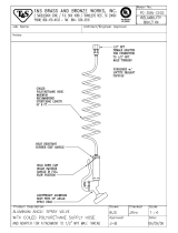 T & S Brass & Bronze Works PG-35AV-CH03 Datasheet
-
 T & S Brass & Bronze Works PG-35AV-CHV Datasheet
-
Hitachi 308996J User manual
-
-
 T & S Brass & Bronze Works PG-35AV-CH02 Datasheet
-
Graco Inc. 207-945 User manual
-
 T & S Brass & Bronze Works PG-35AV-CH05 Datasheet
-
 Great Neck Saw 25862 User guide


