Panasonic WJSX550_SERIES Operating instructions
- Category
- Security camera accessories
- Type
- Operating instructions
Video Input Board
WV-PB5508E
Before attempting to connect or operate this product, please read these instructions completely
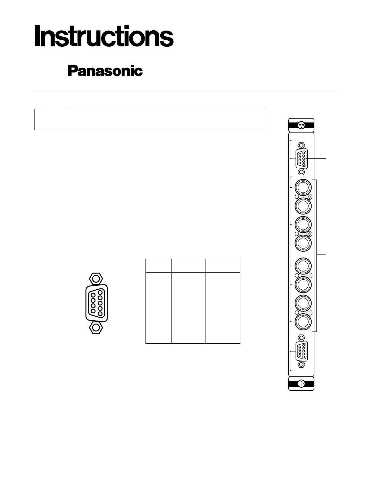
PREFACE
The WV-PB5508E Video Input Board is provided for expanding the video input capability of the WJ-
SX550 Matrix Switcher.
When handling this board, hold only by circuit board edges. Otherwise components on the
board may be damaged by static electricity.
Caution
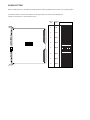
APPEARANCE
1. Video Output Connector (VIDEO OUT 1, 2)
The video signal connected to the Camera Input Connector (CAMERA IN) is looped through to
this connector with 75 ohms termination.
The camera control signal multiplexed on the video signal has been eliminated at this connec-
tor. When the Power Switch of the Matrix Switcher is turned off no signal is obtained at this con-
nector.
BNC female connectors are available by use of optional loop through cable WV-CA64.
2. Camera Input Connector (CAMERA IN, 1 - 8)
This connector accepts either a colour or B/W composite video signal from the camera.
Also VD2, to synchronize cameras in vertical timing, and data, to control camera site devices
such as receivers, intelligent cameras, and combination cameras, are multiplexed through this
connector.
Pin No.
1
2
3
4
5
6
7
8
9
Not used
CH1
GND (CH1)
CH2
GND (CH2)
CH3
GND (CH3)
CH4
GND (CH4)
Not used
CH5
GND (CH5)
CH6
GND (CH6)
CH7
GND (CH7)
CH8
GND (CH8)
VIDEO OUT
1
VIDEO OUT
2
9
8
7
6
5
4
3
2
1
INPUT
1
2
3
4
5
6
7
8
CAMERA IN
VIDEO OUT1
VIDEO OUT2
q
w
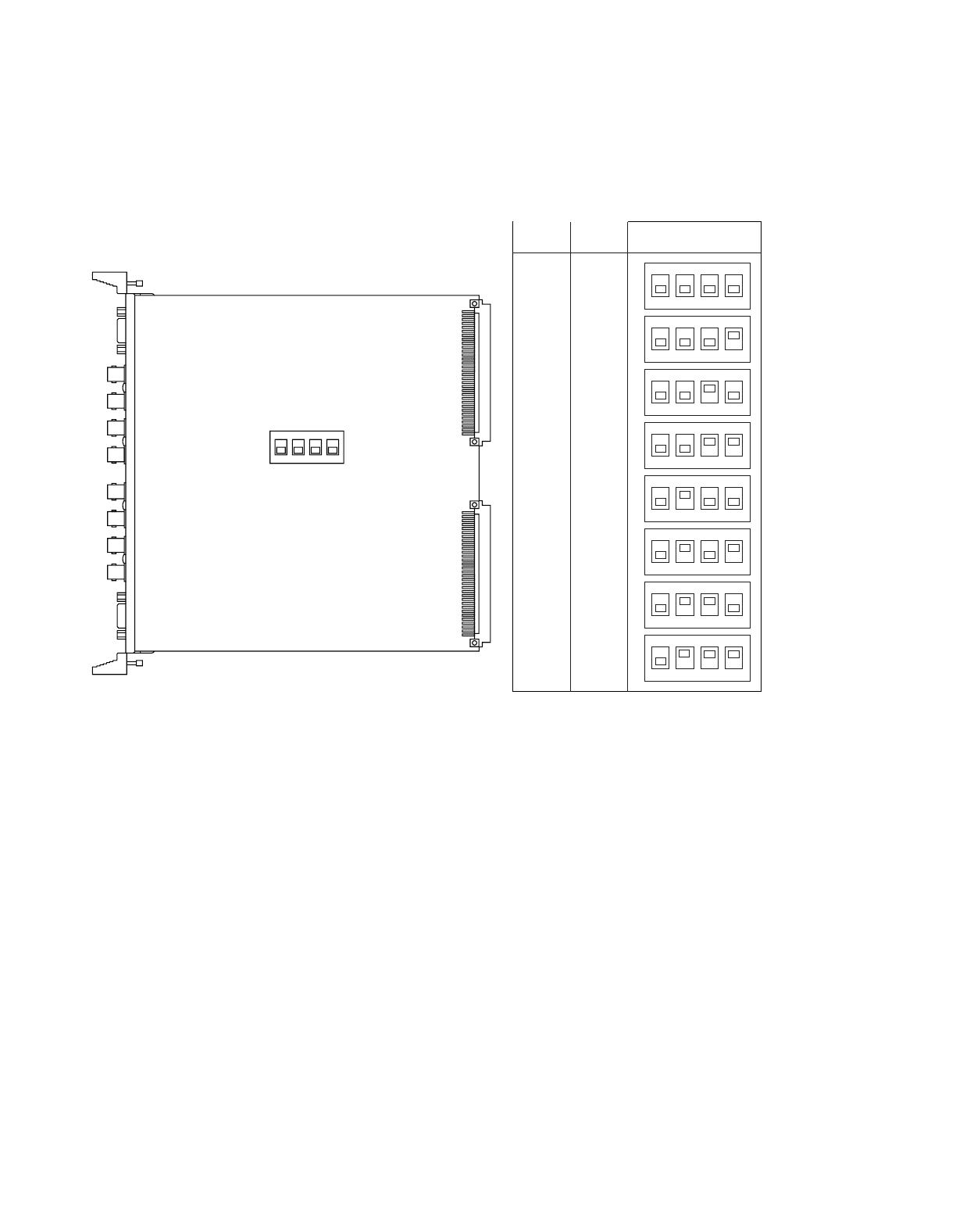
BOARD SETTING
Before installing this board, the following settings should be made by qualified service personnel or system installers.
Set switches (SW1) on the board to meet the camera input number as shown in the following table.
Initially, camera input 1-8 is selected at the factory.
1234
OFF
1234
OFF
1234
OFF
1234
OFF
1234
OFF
1234
OFF
1234
OFF
1234
OFF
BOARD
NO.
1
2
3
4
5
6
7
8
1-8
9-16
17-24
25-32
33-40
41-48
49-56
57-64
CAMERA
IN NO.
SW1 SETTING
1234
OFF
SW1
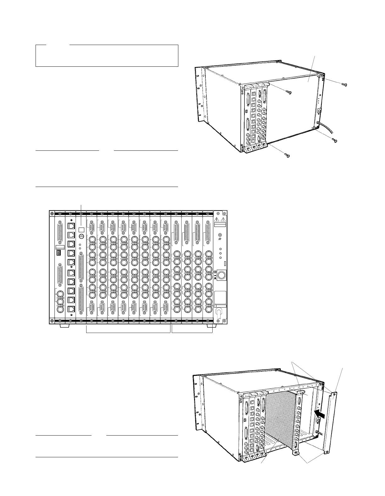
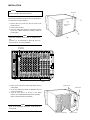
4. Make sure to push in the Video Input Board until it is
seated firmly.
5. Secure the Video Input Board by tightening the two
screws on the board.
6. Close off open spaces on the rear of the Matrix
Switcher by using WV-Q63E Blank Panels (Optional).
(Refer to the instructions for WV-Q63E)
INSTALLATION
Before installing this board be sure to turn off the Power
Switch of the WJ-SX550 Matrix Switcher.
Caution
The following installation should be made by qualified ser-
vice personnel or system installers.
1. Remove the four screws from the rear panel of the
Matrix Switcher.
2. Remove the rear panel.
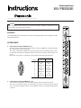
3. Place the Video Input Board into the desired position
in the rear of Matrix Switcher by sliding it inside the
board guides.
Each slot is identical, so the board can installed in any
slot.
However it is recommended to install the board as
shown below for an orderly installation.
Note
Refer to the Operating Instructions of WJ-SX550 for
more details.
Note
Rear Panel
Remove four
screws.
Blank Panel
Tighten screws.
Tighten screws.
Video Input Board
CPU
RS-232C
TIME
ADJUST IN
COM
PRINTER
OUT
IN
VS/VD
VD
OUT
OFF
+9V
+5V
−5V
POWER
ON
11A00001
OUT
IN
1
OUT
IN
2
OUT
IN
3
OUT
IN
4
MONITOR
ALARM OUT
RESET OUT
OUTPUT
OUT
IN
1
OUT
IN
2
OUT
IN
3
OUT
IN
4
MONITOR
ALARM OUT
RESET OUT
OUTPUT
OUT
IN
1
OUT
IN
2
OUT
IN
3
OUT
IN
4
MONITOR
ALARM OUT
RESET OUT
OUTPUT
OUT
IN
1
OUT
IN
2
OUT
IN
3
OUT
IN
4
MONITOR
ALARM OUT
RESET OUT
OUTPUTINPUT
1
2
3
4
5
6
7
8
CAMERA IN
VIDEO OUT1
VIDEO OUT2
INPUT
1
2
3
4
5
6
7
8
CAMERA IN
VIDEO OUT1
VIDEO OUT2
INPUT
1
2
3
4
5
6
7
8
CAMERA IN
VIDEO OUT1
VIDEO OUT2
INPUT
1
2
3
4
5
6
7
8
CAMERA IN
VIDEO OUT1
VIDEO OUT2
INPUT
1
2
3
4
5
6
7
8
CAMERA IN
VIDEO OUT1
VIDEO OUT2
INPUT
1
2
3
4
5
6
7
8
CAMERA IN
VIDEO OUT1
VIDEO OUT2
INPUT
1
2
3
4
5
6
7
8
CAMERA IN
VIDEO OUT1
VIDEO OUT2
INPUT
1
2
3
4
5
6
7
8
CAMERA IN
VIDEO OUT1
VIDEO OUT2
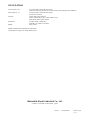
33-64
ALARM
TEST
1-32
00
5
RESET
MODE
CONTROL
DATA 1
DATA 2
DATA 3
DATA 4
DATA 5
DATA 6
DATA 7
DATA 8
TEST 1
TEST 2
Alarm Board
WV-PB5564E
Video Input Board Video Output
Board

N1094-0 YWV8QA3424AN Printed in Japan
N 19
SPECIFICATIONS
Camera Input (1 - 8): 1.0 Vp-p/75 ohms composite video signal
0.5Vp-p/75 ohms data signal and 2.5 Vp-p/75 ohms vertical timing pulse multiplexed
Video Output (1 - 2): 1.0 Vp-p/75 ohms composite video signal
9 pin D-Sub Connector
Function: Camera Site Control: All Input
Cable Compensation: S, M, L (Short, Middle, Long)
Vertical Drive (VD2) Output: On/Off
Dimensions: 24.5(W) x 265(H) x 260(D) mm
15/16"(W) x 10-7/16"(H) x 10-1/4"(D)
Weight: 450g (1.0 lbs.)
Weight and dimensions indicated are approximate.
specifications are subject to change without notice.
Matsushita Electric Industrial Co., Ltd.
Central P.O. Box 288, Osaka 530-91, Japan
-
 1
1
-
 2
2
-
 3
3
-
 4
4


Panasonic WJSX550_SERIES Operating instructions
- Category
- Security camera accessories
- Type
- Operating instructions
Ask a question and I''ll find the answer in the document
Finding information in a document is now easier with AI
Related papers
-
Panasonic WJSX550_SERIES Operating instructions
-
-
-
-
-
-
-
-
-
Other documents
-
JBL 28M User manual
-
ADLINK Technology PCIe-RTV24 User manual
-
Sanyo VPC-X1200BK User manual
-
Vdwall LVP8601 User manual
-
-
Sony SRP-X700P User manual
-
-
-
Texas Instruments TSW1250EVM: High-Speed LVDS Deserializer and Analysis System (Rev. F) User guide
-