Panasonic AM1 (NZ BASIC) User manual
- Category
- Network switches
- Type
- User manual
AM1
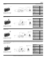
ORDERING INFORMATION
TERMINAL VARIATION
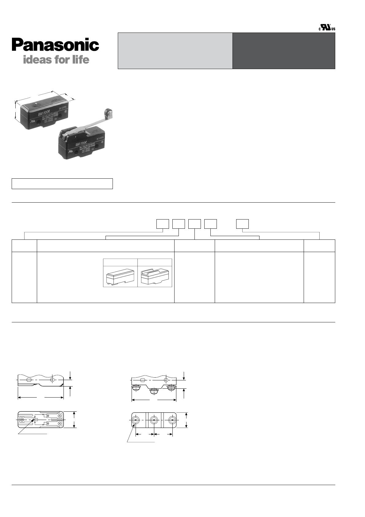
Standard types, reversed action types and oil tight types are available in two terminal designs, solder and screw terminals, as shown
in the above columns:
Differences in dimension between solder and screw terminals are as follows;
HIGH CONTACT CAPACITY,
PRECISE OPERATION
AM1 (NZ BASIC)
SWITCHES
49.2
24.1
17.5
Compliance with RoHS Directive
FEATURES
• 10 A High current switching capacity
and high precision
• Wide allowance of operating speed
• Versatile variety of actuators
• UL/C-UL approved
TYPICAL APPLICATION
• General industrial machinery
• Medical equipment
• Measuring instruments
• Transportation equipment
• Home electric appliances
Type of
switch
NZ basic
(AM1)
switch
Remarks: Not every combination is available. Please refer to the following table, “PRODUCT TYPES”.
Upper body cover shape & terminal Actuators
Basic
specifications
1: Flat, solder terminal
3: Flat, screw terminal
5: Grooved, solder terminal
7: Grooved, screw terminal
Upper body cover shape 0: Pin plunger
1: Hinge lever (leaf spring)
3: Hinge roller lever (roller, leaf, spring)
4: Hinge short roller lever
5: Overtravel plunger
6: Compact overtravel plunger
7: Panel mount plunger
811: Panel mount roller plunger
812: Panel mount cross roller plunger
Contact
F: Cadmium
free
0: Standard type
1: Oil tight type
3: Reversed
action type
4: One way type
Ex. AM 1 5 0 1 K F
Flat Grooved
Solder terminal
mm
Screw terminal
N.O.
N.C.
CIRCUT
CIRCUT
Terminal plate
17.5
6.3
49.2
17.5
20.219.8
CNONC
9.1
49.2
M4 screw P0.7
All Rights Reserved © C
OPYRIGHT Panasonic Electric Works Co., Ltd.

AM1
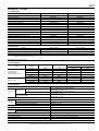
PRODUCT TYPES
1. Standard type
2. Oil tight types
Remarks: 1. Standard part number indicates UL/C-UL mark.
2. Standard packing for inner carton: 20cps.
SPECIFICATIONS
1. Contact Rating
2. Characteristics
Actuator Solder terminal Screw terminal
Pin plunger AM1100KF AM1300KF
Over travel plunger AM1105KF AM1305KF
Compact over travel plunger AM1106KF AM1306KF
Panel mount plunger AM1107KF AM1307KF
Panel mount roller plunger AM110811KF AM130811KF
Panel mount cross roller plunger AM110812KF AM130812KF
Flexible leaf lever AM1101KF AM1301KF
Flexible roller leaf lever AM1103KF AM1303KF
Rigid lever AM1501KF AM1701KF
Rigid short roller lever AM1504KF AM1704KF
Rigid roller lever AM1503KF AM1703KF
One way type•Rigid short roller lever AM1544KF AM1744KF
One way type•Rigid roller lever AM1543KF AM1743KF
Reversed action type•Rigid lever AM1531KF AM1731KF
Reversed action type •Rigid short roller lever AM1534KF AM1734KF
Reversed action type•Rigid roller lever AM1533KF AM1733KF
Actuator Solder terminal Screw terminal
Rigid lever AM1511KF AM1711KF
Rigid short roller lever AM1514KF AM1714KF
Rigid roller lever AM1513KF AM1713KF
Type Voltage
Resistive load
(cos
φ
= 1)
Inductive load
(cos
φ
= 0.6 to 0.7)
Motor or lamp load
N.C. N.O.
Standard types
One way types
Reversed action types
125 V AC 10 A 6 A 3 A 1.5 A
250 V AC 10 A 6 A 2 A 1 A
480 V AC 1 A 0.5 A — —
125 V DC 0.5 A 0.05 A — —
250 V DC 0.25 A 0.03 A — —
Oil tight types
125 V AC 10 A 6 A 3 A 1.5 A
250 V AC 10 A 6 A 2 A 1.0 A
125 V DC 0.5 A 0.05 A — —
Item Specifications
Expected
life
Mechanical
Pin plunger types (O.T.: specified value)
Min. 2 ×10
7
(60 cpm) (at rated overtravel)
(Oil tight: Min. 1.5 ×10
6
)
Other types (O.T.: specified value)
Min. 5 ×10
6
(60 cpm) (at rated overtravel)
(Oil tight: Min. 1.5 ×10
6
)
Electrical (O.T.: Max.)
Min. 5 ×10
5
(20 cpm) (at rated load)
(Oil tight: Min. 1.5 ×10
5
)
Insulation resistance Min. 100 MΩ(at 500 V DC)
Dielectric
strength
Between open terminals 1,000 Vrms for 1 min.
Between each terminal and other exposed metal parts 2,000 Vrms for 1 min.
Between each terminal and ground 2,000 Vrms for 1 min.
Contact resistance (initial) (by voltage drop, 1 A, 6–8 V DC) Max. 50 mΩ
Vibration resistance (Pin plunger type) Single amplitude: 0.75 mm, 10 to 55 Hz (contact opening: max. 1 msec.)
Shock
resistance
Pin plunger types Min. 300 m/s
2
(contact opening: max. 1 msec.)
Other types Min. 50 m/s
2
(contact opening: max. 1 msec.)
Allowable operating speed (at no load) 0.1 to 1,000 mm/sec. (at pin plunger position)
Max. operating cycle rate (at no load) 240 cpm
Ambient temperature –25°C to +80°C (no freezing at low temperature)
Weight Approx. 20 to 55 g
All Rights Reserved © C
OPYRIGHT Panasonic Electric Works Co., Ltd.

AM1
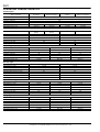
OPERATING CHARACTERISTICS
Standard types
Standard types (cont' d)
One way types
Reversed action types
Oil tight types
Types of actuator Pin plunger Overtravel plunger
Compact overtravel
plunger
Panel mount plunger
Operating force, max. 3.63 N
Release force, min. 1.12 N
Pretravel, max. mm 0.4
Movement differential, max. mm 0.05
Overtravel, min. mm 0.13 1.5 1.5 5.6
Operating position, mm 15.9±0.4 28.2±0.5 21.2±0.5 21.8±0.8
Types of actuator
Panel mount roller
plunger
Panel mount cross roller
plunger
Flexible leaf lever Flexible roller leaf lever
Operating force, max. 3.63 N 1.47 N
Release force, min. 1.12 N 0.14 N
Pretravel, max. mm 0.4 4
Movement differential, max. mm 0.05 1.3
Overtravel, min. mm 3.6 1.6
Operating position, mm 33.3±1.2 17.5±0.8 28.6±0.8
Types of actuator Rigid lever Rigid short roller lever Rigid roller lever
Operating force, max. 0.69 N 1.57 N 0.98 N
Release force, min. 0.14 N 0.42 N 0.2 N
Pretravel, max. mm 10 4.5 7.5
Movement differential, max. mm 1.3 0.7 1.3
Overtravel, min. mm 5.6 2.4 3.6
Operating position, mm 19.1±0.7 30.2±0.4 30.2±0.7
Types of actuator Rigid short roller lever Rigid roller lever
Operating force, max. 2.23 N 1.67 N
Release force, min. 0.42 N 0.42 N
Pretravel, max. mm 3.5 4.5
Movement differential, max. mm 0.4 0.5
Overtravel, min. mm 1.5 2.4
Free position, max. mm 31.8 43.3
Operating position, mm 30.2±0.4 41.3±0.4
Types of actuator Rigid lever Rigid short roller lever Rigid roller lever
Operating force, max. 1.67 N 5.30 N 2.35 N
Release force, min. 0.27 N 1.67 N 0.56 N
Pretravel, max. mm 5.0 2.5 3.6
Movement differential, max. mm 0.9 0.4 0.7
Overtravel, min. mm 5.6 2.0 4.0
Operating position, mm 19.1±0.8 30.2±0.5 30.2±0.8
Types of actuator Rigid lever Rigid short roller lever Rigid roller lever
Operating force, max. 0.69 N 1.67 N 0.98 N
Release force, min. 0.14 N 0.42 N 0.20 N
Pretravel, max. mm 10 4.5 7.5
Movement differential, max. mm 1.5 0.7 1.3
Overtravel, min. mm 5.6 2.4 3.6
Operating position, mm 19.1±0.7 30.2±0.4 30.2±0.7
All Rights Reserved © C
OPYRIGHT Panasonic Electric Works Co., Ltd.
AM1
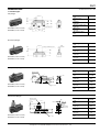
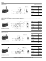
DIMENSIONS
mm General tolerance: ±0.4
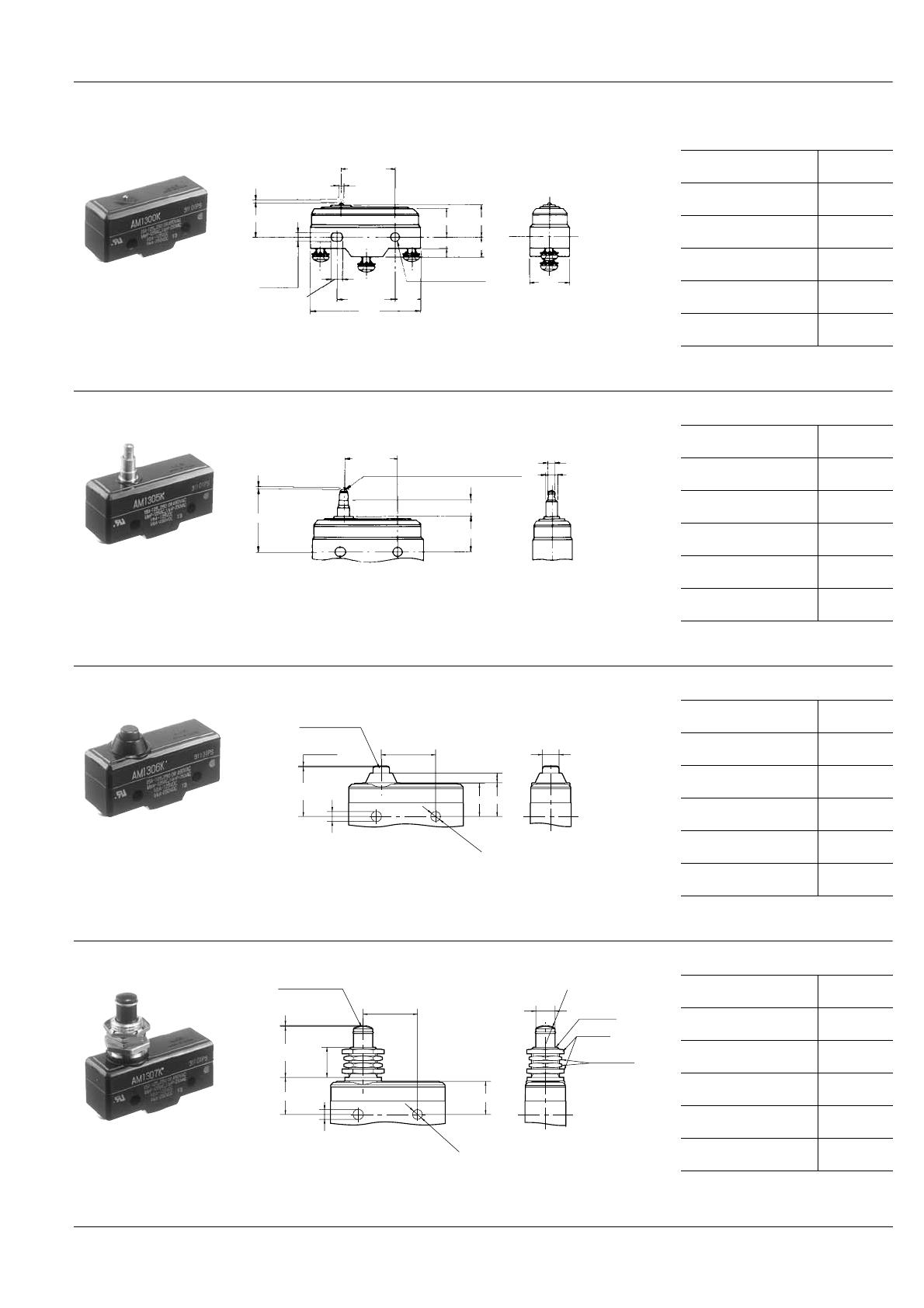
1. Standard types
Pin plunger
AM1100KF (Solder terminal)
AM1300KF (Screw terminal)
2.4
14.6 15
17.5
9.1
5.4
23.3±0.3
4.5±0.1
25.4±0.1
49.2
11.9
O.P.
P. T .
4.2
+0.1
−0.05
4.2 dia. hole
+0.1
−0.05
Operating force,
max.
3.63 N
Release force,
min.
1.12 N
Pretravel,
max. mm
0.4
Movement differential,
max. mm
0.05
Overtravel,
min. mm
0.13
Operating position,
mm
15.9±0.4
Overtravel plunger
AM1105KF (Solder terminal)
AM1305KF (Screw terminal)
8.4
4 dia.
6.35 dia.
15
23.3±0.3
O.P.
P. T .
Plunger: Hardening steel
Operating force,
max.
3.63 N
Release force,
min.
1.12 N
Pretravel,
max. mm
0.4
Movement differential,
max. mm
0.05
Overtravel,
min. mm
1.5
Operating position,
mm
28.2±0.5
Compact over plunger
AM1106KF (Solder terminal)
AM1306KF (Screw terminal)
–0.05
+0.10
4.2
Plunger: Plastic
7.1 dia.
4.2
P.T.
0.4 max.
23.3
±0.3
21.2
O.P.
±0.5
14.3
14.5
4.2
+0.10
–0.05
dia.
Operating force,
max.
3.63 N
Release force,
min.
1.12 N
Pretravel,
max. mm
0.4
Movement differential,
max. mm
0.05
Overtravel,
min. mm
1.5
Operating position,
mm
21.2±0.5
Panel mount plunger
AM1107KF (Solder terminal)
AM1307KF (Screw terminal)
8.25 dia.
16
Nut (2 thick)
Lock nut
(2 thick)
M12 × P1
±0.5
–0.05
+0.10
4.2
Plunger: Plastic
P.T.
0.4 max.
23.3
±0.3
21.8
O.P.
±0.8
14.3
13.1
4.2
+0.10
–0.05
dia.
R8
Operating force,
max.
3.63 N
Release force,
min.
1.12 N
Pretravel,
max. mm
0.4
Movement differential,
max. mm
0.05
Overtravel,
min. mm
5.6
Operating position,
mm
21.8±0.8
All Rights Reserved © C
OPYRIGHT Panasonic Electric Works Co., Ltd.

AM1
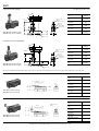
Panel mount roller plunger
mm General tolerance: ±0.4
Dimensions and Operating characteristics are the same as those of Panel mount roller plunger type. However, the roller joins the switch body at an angle of 90°.
AM110811KF (Solder terminal)
AM130811KF (Screw terminal)
90°
: Plastic
M12 × P1
Roller 12.7 dia. × 4.6
Nut (2 thick)
16
±0.5
–0.05
+0.10
4.2
P.T.
0.4 max.
23.3
±0.3
33.3
O.P.
±1.2
14.3
4.2
+0.10
–0.05
dia.
15.5
Operating force,
max.
3.63 N
Release force,
min.
1.12 N
Pretravel,
max. mm
0.4
Movement differential,
max. mm
0.05
Overtravel,
min. mm
3.6
Operating position,
mm
33.3±1.2
Panel mount cross roller plunger
AM110812KF (Solder terminal)
AM130812KF (Screw terminal)
90°
M12 × P1
Nut (2 thick)
: Plastic
Roller 12.7 dia. × 4.6
16
±0.5
–0.05
+0.10
4.2
P.T.
0.4 max.
23.3
±0.3
33.3
O.P.
±1.2
14.3
4.2
+0.10
–0.05
dia.
15.5
Operating force,
max.
3.63 N
Release force,
min.
1.12 N
Pretravel,
max. mm
0.4
Movement differential,
max. mm
0.05
Overtravel,
min. mm
3.6
Operating position,
mm
33.3±1.2
Flexible leaf lever
AM1101KF (Solder terminal)
AM1301KF (Screw terminal)
14.6
4.8
49.6±0.8
F. P.
O.P.
Leaf: Stainless steel
Operating force,
max.
1.47 N
Release force,
min.
0.14 N
Pretravel,
max. mm
4
Movement differential,
max. mm
1.3
Overtravel,
min. mm
1.6
Operating position,
mm
17.5±0.8
Flexible roller leaf lever
AM1103KF (Solder terminal)
AM1303KF (Screw terminal)
14.6
46±0.8
F. P. O.P.
Leaf: Stainless steel
Roller 9.5 dia.×4:
Plastic
Operating force,
max.
1.47 N
Release force,
min.
0.14 N
Pretravel,
max. mm
4
Movement differential,
max. mm
1.3
Overtravel,
min. mm
1.6
Operating position,
mm
28.6±0.8
All Rights Reserved © C
OPYRIGHT Panasonic Electric Works Co., Ltd.

AM1
Rigid lever
mm General tolerance: ±0.4
AM1501KF (Solder terminal)
AM1701KF (Screw terminal)
26.1
20.1±0.5
F. P.
O.P.
R63.5
Lever: Stainless steel
4.8
Operating force,
max.
0.69 N
Release force,
min.
0.14 N
Pretravel,
max. mm
10
Movement differential,
max. mm
1.3
Overtravel,
min. mm
5.6
Operating position,
mm
19.1±0.7
Rigid short roller lever
AM1504KF (Solder terminal)
AM1704KF (Screw terminal)
26.1
20.1±0.5
F. P.
O.P.
R26.7
Roller 9.5 dia.×4:
Plastic
Operating force,
max.
1.57 N
Release force,
min.
0.42 N
Pretravel,
max. mm
4.5
Movement differential,
max. mm
0.7
Overtravel,
min. mm
2.4
Operating position,
mm
30.2±0.4
Rigid roller lever
AM1503KF (Solder terminal)
AM1703KF (Screw terminal)
26.1
20.1±0.5
F. P.
O.P.
R48.3
Roller 9.5 dia.×4:
Plastic
Operating force,
max.
0.98 N
Release force,
min.
0.2 N
Pretravel,
max. mm
7.5
Movement differential,
max. mm
1.3
Overtravel,
min. mm
3.6
Operating position,
mm
30.2±0.7
2. One way types
This type is operated only to one direction, not to the reversed direction by the construction of the roller lever, pivoting away from the
cam on the return stroke.
Rigid short roller lever
AM1544KF (Solder terminal)
AM1744KF (Screw terminal)
26.1
27.8 max.
20.1±0.5
F. P.
O.P.
R21.1
Roller 4.75 dia.×4.75:
Plastic
Operating force,
max.
2.23 N
Release force,
min.
0.42 N
Pretravel,
max. mm
3.5
Movement differential,
max. mm
0.4
Overtravel,
min. mm
1.5
Operating position,
mm
30.2±0.4
All Rights Reserved © C
OPYRIGHT Panasonic Electric Works Co., Ltd.

AM1
Rigid roller lever
mm General tolerance: ±0.4
AM1543KF (Solder terminal)
AM1743KF (Screw terminal)
26.1
34.1 max.
20.1±0.5
O.P.
F. P.
R31
Roller 9.5 dia.×4:
Plastic
Operating force,
max.
1.67 N
Release force,
min.
0.42 N
Pretravel,
max. mm
4.5
Movement differential,
max. mm
0.5
Overtravel,
min. mm
2.4
Operating position,
mm
41.3±0.4
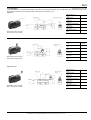
3. Reversed action types
When the actuator is operated, the switching mechanism returns to the free position. Extraordinary force by pushing the plunger too
much is not put on the switching mechanism, which means stability in life.
Rigid lever
AM1531KF (Solder terminal)
AM1731KF (Screw terminal)
18.7
17.5
20.1±0.5
4.5±0.1
25.4±0.1
9.1
11.9 11.9
49.2
16.9±0.8
F. P.
Lever: Stainless steel
O.P.
R56
4.2
+0.1
−0.05
4.2 dia. hole
+0.1
−0.05
4.8
Operating force,
max.
1.67 N
Release force,
min.
0.27 N
Pretravel,
max. mm
5.0
Movement differential,
max. mm
0.9
Overtravel,
min. mm
5.6
Operating position,
mm
19.1±0.8
Rigid short roller lever
AM1534KF (Solder terminal)
AM1734KF (Screw terminal)
18.7
20.1±0.5
F. P.
O.P.
R19
Roller 9.5 dia.×4:
Plastic
Operating force,
max.
5.30 N
Release force,
min.
1.67 N
Pretravel,
max. mm
2.5
Movement differential,
max. mm
0.4
Overtravel,
min. mm
2.0
Operating position,
mm
30.2±0.5
Rigid roller lever
AM1533KF (Solder terminal)
AM1733KF (Screw terminal)
18.7
20.1±0.5
F. P.
O.P.
R41
Roller 9.5 dia.×4:
Plastic
Operating force,
max.
2.35 N
Release force,
min.
0.56 N
Pretravel,
max. mm
3.6
Movement differential,
max. mm
0.7
Overtravel,
min. mm
4.0
Operating position,
mm
30.2±0.8
All Rights Reserved © C
OPYRIGHT Panasonic Electric Works Co., Ltd.
AM1
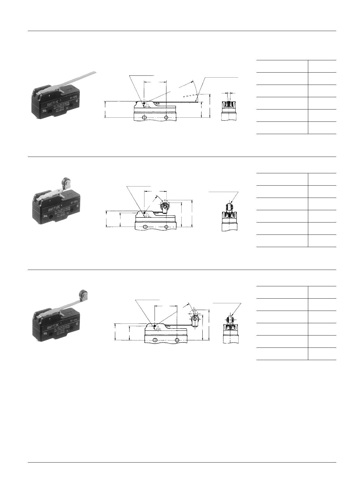
4. Oil tight types
mm General tolerance: ±0.4
The pushbutton part is sealed with the rubber cap and the connected part between the cap and body is also coated with resin so that
these parts are kept away from foreign matters. This type has resistance to oil.
Rigid lever
AM1511KF (Solder terminal)
AM1711KF (Screw terminal)
26.1
20.1±0.5
F. P.
O.P.
R63.5
Plunger seal
4.8
Lever: Stainless steel
Operating force,
max.
0.69 N
Release force,
min.
0.14 N
Pretravel,
max. mm
10
Movement differential,
max. mm
1.5
Overtravel,
min. mm
5.6
Operating position,
mm
19.1±0.7
Rigid short roller lever
AM1514KF (Solder terminal)
AM1714KF (Screw terminal)
26.1
20.1±0.5
16.9±0.8
F. P.
O.P.
R26.7
Plunger seal
Roller 9.5 dia.×4:
Plastic
Operating force,
max.
1.67 N
Release force,
min.
0.42 N
Pretravel, max.
mm
4.5
Movement differential,
max. mm
0.7
Overtravel,
min. mm
2.4
Operating position,
mm
30.2±0.4
Rigid roller lever
AM1513KF (Solder terminal)
AM1713KF (Screw terminal)
26.1
20.1±0.5
16.9±0.8
F. P.
O.P.
R48.3
Plunger seal
Roller 9.5 dia.×4:
Plastic
Operating force,
max.
0.98 N
Release force,
min.
0.20 N
Pretravel,
max. mm
7.5
Movement differential,
max. mm
1.3
Overtravel,
min. mm
3.6
Operating position,
mm
30.2±0.7
All Rights Reserved © C
OPYRIGHT Panasonic Electric Works Co., Ltd.

AM1
NOTES
1. Regarding fastening of switch body
1) In fastening the switch body, use M4
mounting screws to attach switches with
the torque 1.5 N·m or less.
2) After mounting and wiring, the
insulation distance between ground and
each terminal should be confirmed as
sufficient.
2. Adjustment of the operating device
The operating device should be
positioned so that it applies no stress to
the pushbutton or actuator when the
switch is in the open position. If this
condition is exceeded, the mechanical
and electrical performance will be
impaired. In addition, the force applied by
the operating device should be in a
perpendicular direction. Even if the
pushbutton is used in the full total travel
position, there will be no influence on the
life of the switch.
3. Soldering operations
Soldering should be done in less than 5
seconds, with a 60 watt iron (tip
temperature = 350°C max.). Care should
be taken not to apply force to the terminal
during soldering.
4. Avoid using switches in the
following conditions:
• In corrosive gases such as hydrogen
sulfide.
• In flammable or explosive gases such
as gasoline or thinner etc.
• In a dusty environment.
• In an ambient humidity over 85%.
• In conditions where the perpendicular
operating speed is less than 0.1 mm/sec.
or more than 1,000 mm/sec.
• In a silicon atmosphere.
5. Others
Caution should be taken not to drop
switches.
All Rights Reserved © C
OPYRIGHT Panasonic Electric Works Co., Ltd.
-
 1
1
-
 2
2
-
 3
3
-
 4
4
-
 5
5
-
 6
6
-
 7
7
-
 8
8
-
 9
9


Panasonic AM1 (NZ BASIC) User manual
- Category
- Network switches
- Type
- User manual
Ask a question and I''ll find the answer in the document
Finding information in a document is now easier with AI
Related papers
Other documents
-
Honeywell EVN2000 Series User manual
-
-
-
-
-
Renishaw TP7M User guide
-
Honeywell GSS Series User manual
-
Eaton Vikers V200 Series Operating instructions
-
Beretta Steel I User manual
-