General International 15-155 M1 Setup & Operation Manual
- Category
- Power sanders
- Type
- Setup & Operation Manual

VERSION 2_ REVISION 2 - APRIL 4, 2014 (19094510)
© COPYRIGHT GENERAL INTERNATIONAL
Heavy duty open steel stand for greater
stability.
High quality conveyor belt for longer
service life.
Large hand wheel adjusts conveyor
table height.
Graduated depth scale in both inches
and metric to indicate sanding thickness.
Independent switches with removable
safety key for both conveyor motor and
main motor.
4” dust outlet.
MAXIMUM SANDING WIDTH
13” (330 MM)
MAXIMUM SANDING THICKNESS
3 3⁄4” (95 MM)
MINIMUM SANDING THICKNESS
1⁄4” (6 MM)
MINIMUM SANDING LENGTH
5” (127 MM)
DRUM DIAMETER
5” (127 MM)
DRUM SPEED
1550 RPM
FEEDING SPEED
6 TO 20 FPM (1.8 TO 6.2 M/MIN)
MAIN MOTOR
1 1⁄2 HP, 110 V, 13 A
CONVEYOR MOTOR
1⁄15 HP
WEIGHT (WITH STAND)
298 LBS (135.4 KG)

THANK YOU
for choosing this General
®
International model 15-155 13”
Horizontal Single Drum Sander. This sander has been carefully tested and inspected before
shipment and if properly used and maintained, will provide you with years of reliable service.
To ensure optimum performance and trouble-free operation, and to get the most from your
investment, please take the time to read this manual before assembling, installing and ope-
rating the unit.
The manual’s purpose is to familiarize you with the safe operation, basic function, and features
of this sander as well as the set-up, maintenance and identification of its parts and compo-
nents. This manual is not intended as a substitute for formal woodworking instruction, nor to
offer the user instruction in the craft of woodworking. If you are not sure about the safety of
performing a certain operation or procedure, do not proceed until you can confirm, from
knowledgeable and qualified sources, that it is safe to do so.
Once you’ve read through these instructions, keep this manual handy for future reference.
Disclaimer:
The information and specifications in this
manual pertain to the unit as it was supplied from the
factory at the time of printing. Because we are commit-
ted to making constant improvements, General
®
International reserves the right to make changes to
components, parts or features of this unit as deemed
necessary, without prior notice and without obligation to
install any such changes on previously delivered units.
Reasonable care is taken at the factory to ensure that
the specifications and information in this manual corres-
ponds with that of the unit with which it was supplied.
However, special orders and “after factory” modifica-
tions may render some or all information in this manual
inapplicable to your machine. Further, as several gene-
rations of this model of sander and several versions of
this manual may be in circulation, if you own an earlier
or later version of this unit, this manual may not depict
your machine exactly. If you have any doubts or ques-
tions contact your retailer or our support line with the
model and serial number of your unit for clarification.
GENERAL® INTERNATIONAL
8360 Champ-d’Eau, Montreal (Quebec) Canada H1P 1Y3
Telephone (514) 326-1161 • Fax (514) 326-5555 • www.general.ca

GENERAL
®
& GENERAL
®
INTERNATIONAL WARRANTY
All component parts of General®, General® International and Excalibur by General
International ® products are carefully inspected during all stages of production and each unit
is thoroughly inspected upon completion of assembly.
Limited Lifetime
Warranty
Because of our commitment to quality and customer satisfaction, General® and General®
International agree to repair or replace any part or component which upon examination,
proves to be defective in either workmanship or material to the original purchaser for the life
of the tool.
However, the Limited Lifetime Warranty does not cover any product used for profes-
sionnal or commercial production purposes nor for industrial or educational applications.
Such cases are covered by our Standard 2-year Limited Warranty only. The Limited Lifetime
Warranty is also subject to the “Conditions and Exceptions” as listed below.
Standard 2-Year Limited Warranty
All products not covered by our lifetime warranty including products used in commercial,
industrial and educational applications are warranted for a period of 2 years (24 months) from
the date of purchase. General® and General® International agree to repair or replace any
part or component which upon examination, proves to be defective in either workmanship or
material to the original purchaser during this 2-year warranty period, subject to the “conditions
and exceptions” as listed below.
T
o file a Claim
To file a claim under our Standard 2-year Limited Warranty or under our Limited Lifetime
Warranty, all defective parts, components or machinery must be returned freight or postage
prepaid to General® International, or to a nearby distributor, repair center or other location
designated by General® International. For further details call our service department at 1-888-
949-1161 or your local distributor for assistance when filing your claim.
Along with the return of the product being claimed for warranty, a copy of the original proof
of purchase and a “letter of claim” must be included (a warranty claim form can also be used
and can be obtained, upon request, from General® International or an authorized distributor)
clearly stating the model and serial number of the unit (if applicable) and including an expla-
nation of the complaint or presumed defect in material or workmanship.
CONDITIONS AND EXCEPTIONS:
This coverage is extended to the original purchaser only. Prior warranty registration is not
required but documented proof of purchase i.e. a copy of original sales invoice or receipt
showing the date and location of the purchase as well as the purchase price paid, must be
provided at the time of claim.
Warranty does not include failures, breakage or defects deemed after inspection by General®
or General® International to have been directly or indirectly caused by or resulting from:
improper use, or lack of or improper maintenance, misuse or abuse, negligence, accidents,
damage in handling or transport, or normal wear and tear of any generally considered con-
sumable parts or components.
Repairs made without the written consent of General® International
l
will void all warranty.

TABLE OF CONTENTS
SAFETY RULES . . . . . . . . . . . . . . . . . . . . . . .5
ELECTRICAL REQUIREMENTS . . . . . . . . . . . . . .6
Grounding instructions . . . . . . . . . . . . . . . . . . . . . . .6
Circuit capacity . . . . . . . . . . . . . . . . . . . . . . . . . . . . .6
Extension cords . . . . . . . . . . . . . . . . . . . . . . . . . . . . .6
IDENTIFICATION OF MAIN PARTS AND
COMPONENTS . . . . . . . . . . . . . . . . . . . . . . .7
BASIC FUNCTIONS . . . . . . . . . . . . . . . . . . . .8
UNPACKING . . . . . . . . . . . . . . . . . . . . . . . .8
List of contents . . . . . . . . . . . . . . . . . . . . . . . . . . . . . .8
Additional requirements for set up . . . . . . . . . . . . .9
ASSEMBLY INSTRUCTIONS . . . . . . . . . . . . . .9
Install the carrying handles . . . . . . . . . . . . . . . . . . . .9
Install the conveyor height adjustment
hand wheel . . . . . . . . . . . . . . . . . . . . . . . . . . . . . . . .9
Assemble the stand . . . . . . . . . . . . . . . . . . . . . . . . . .9
Fasten the sander to the stand or to your
shop-made bench . . . . . . . . . . . . . . . . . . . . . . . . .10
CONNECTING TO A DUST COLLECTOR . . . . . . .10
BASIC ADJUSTMENTS & CONTROLS
. . . . . . .11
Connecting to a power source . . . . . . . . . . . . . . .11
ON/OFF power switches . . . . . . . . . . . . . . . . . . . . .11
Drum motor ON/OFF switch . . . . . . . . . . . . . . . . . .11
Conveyor motor ON/OFF switch . . . . . . . . . . . . . .11
Raising/Lowering the conveyor table . . . . . . . . .12
Changing feed speed . . . . . . . . . . . . . . . . . . . . . .12
OPERATING INSTRUCTIONS . . . . . . . . . . . . .13
Checking before starting . . . . . . . . . . . . . . . . . . . .13
Operations step-by-step . . . . . . . . . . . . . . . . . . . . .14
To stop the machine . . . . . . . . . . . . . . . . . . . . . . . .14
CHANGING/REPLACING THE SANDING BELT . . .15
Removing the sanding belt . . . . . . . . . . . . . . . . . .15
Mounting a new sanding belt . . . . . . . . . . . . .16-18
LUBRICATION . . . . . . . . . . . . . . . . . . . . . . .18
PERIODIC MAINTENANCE . . . . . . . . . . . . . . .19
REQUIRED MAINTENANCE . . . . . . . . . . . . .19-20
RECOMMENDED OPTIONAL ACCESSORIES . . . .20
PARTS LIST AND DIAGRAMS . . . . . . . . . . .21-29

RULES FOR SAFE OPERATION
To help ensure safe operation, please take a moment to learn the machine’s applications and limitations, as well as poten-
tial hazards. General® International disclaims any real or implied warranty and holds itself harmless for any injury that
may result from improper use of its equipment.
1. Do not operate the sander when tired, distracted,
or under the effects of drugs, alcohol or any medi-
cation that impairs reflexes or alertness.
2. The working area should be well lit, clean and free
of debris.
3. Keep children and visitors at a safe distance when
the sander is in operation; do not permit them to
operate the sander.
4. Childproof and tamper proof your shop and all
machinery with locks, master electrical switches
and switch keys, to prevent unauthorized or unsu-
pervised use.
5. Stay alert! Give your work your undivided atten-
tion. Even a momentary distraction can lead to seri-
ous injury.
6. Fine particulate dust is a carcinogen that can be
hazardous to health. Work in a well-ventilated area
and wear eye, ear and respiratory protection
devices.
7. Do not operate this sander without an ade-
quate dust collection system properly installed and
running. Operating this sander without adequate
dust collection can lead to equipment malfunction
or dangerous situations for the operator or other
individuals in the workshop.
8. Do not wear loose clothing, gloves, bracelets, neck-
laces or other jewelry while the sander is in opera-
tion. Wear protective hair covering to contain long
hair and wear non-slip footwear.
9. Be sure that adjusting wrenches, tools, drinks and
other clutter are removed from the machine and/or
the feed table surface before operating.
10. Keep hands well away from the sanding belts and
all moving parts. Use a brush, not hands, to clear
away sanding dust.
11. Be sure sanding belts are securely installed on the
sanding drums.
12. Do not operate the sander if the sanding belts are
damaged or badly worn.
13. Do not push or force the workpiece into the sander.
The machine will perform better and more safely
when working at the feed rate for which it was
designed.
14. Avoid working from awkward or off balance posi-
tions. Do not overreach and keep both feet on floor.
15. To minimize risk of injury in the event of workpiece
kickback, never stand directly in-line with the sand-
ing belt or in the potential kickback path of the
work piece.
16. Keep guards in place and in working order. If a
guard must be removed for maintenance or clea-
ning, be sure it is properly re-attached before using
the tool again.
17. Never leave the machine unattended while it is run-
ning or with the power on.
18. Use of parts and accessories NOT recommended
by
GENERAL® INTERNATIONAL
may result in equip-
ment malfunction or risk of injury.
19. Never stand on the machine. Serious injury could
occur if the sander is tipped over or if the sanding
belt is unintentionally contacted.
20. Always disconnect the tool from the power source
before servicing, changing accessories or sanding
belts, or before performing any maintenance or
cleaning, or if the machine will be left unattended.
21. Make sure that switch is in “OFF” position before
plugging in the power cord.
22. Make sure the tool is properly grounded. If equip-
ped with a 3-prong plug it should be used with a
three-pole receptacle. Never remove the third
prong.
23. Do not use the sander for other than its inten-
ded use. If used for other purposes,
GENERAL® INTER
NATIONAL
disclaims any real implied warranty and
holds itself harmless for any injury, which may result
from that use.
5

6
ELECTRICAL REQUIREMENTS
GROUNDING INSTRUCTIONS
In the event of an electrical malfunction or short circuit,
grounding reduces the risk of electric shock. The motor
of this machine is wired for 110V single phase operation
and is equipped with a 3-conductor cord and a 3-
prong grounding plug A to fit a grounded type recep-
tacle B. Do not remove the 3rd prong (grounding pin) to
make it fit into an old 2-hole wall socket or extension
cord. If an adaptor plug is used C, it must be attached
to the metal screw of the receptacle.
Note: The use of an adaptor plug is illegal in some
areas. Check your local codes. If you have any doubts
or if the supplied plug does not correspond to your elec-
trical outlet, consult a qualified eletrician before pro-
ceeding.
CIRCUIT CAPACITY
Make sure that the wires in your circuit are capable of
handling the amperage draw from your machine, as
well as any other machines that could be operating on
the same circuit. If you are unsure, consult a qualified
electrician. If the circuit breaker trips or the fuse blows
regularly, your machine may be operating on a circuit
that is close to its amperage draw capacity. However, if
an unusual amperage draw does not exist and a
power failure still occurs, contact a qualified technician
or our service department.
BEFORE CONNECTING THE MACHINE TO THE POWER SOURCE, VERIFY THAT THE VOLTAGE OF YOUR POWER SUPPLY CORRESPONDS
WITH THE VOLTAGE SPECIFIED ON THE MOTOR I.D. NAMEPLATE. A POWER SOURCE WITH GREATER VOLTAGE THAN NEEDED CAN
RESULT IN SERIOUS INJURY TO THE USER AS WELL AS DAMAGE TO THE MACHINE. IF IN DOUBT, CONTACT A QUALIFIED ELECTRICIAN
BEFORE CONNECTING TO THE POWER SOURCE.
THIS TOOL IS FOR INDOOR USE ONLY. DO NOT EXPOSE TO RAIN OR USE IN WET OR DAMP LOCATIONS.
EXTENSION CORDS
If you find it necessary to use an extension cord with your
machine, use only 3-wire extension cords that have 3-
prong grounding plug and a matching 3-pole recepta-
cle that accepts the tool’s plug. Repair or replace a
damaged extension cord or plug immediately.
Make sure the cord rating is suitable for the amperage
listed on the motor I.D. plate. An undersized cord will
cause a drop in line voltage resulting in loss of power
and overheating. The accompanying chart shows the
correct size extension cord to be used based on cord
length and motor I.D. plate amp rating. If in doubt, use
the next heavier gauge. The smaller the number, the
heavier the gauge.
AMPERES
(AMPS)
EXTENSION CORD LENGTH
25 FEET 50 FEET 100 FEET 150 FEET
< 5
18 16 16 14
6 TO 10 18 16 14 12
10 TO 12 16 16 14 14
12 TO 16 14 12
* NR * NR
* NR = Not Recommended
A
B
C

13” HORIZONTAL SINGLE DRUM SANDER
15-155 M1
IDENTIFICATION OF MAIN PARTS AND COMPONENTS
A - CONVEYOR TABLE HEIGHT
ADJUSTMENT HAND WHEEL
B - DUST OUTLET
C - CONVEYOR MOTOR START/STOP
SWITCH WITH SAFETY KEY
D - CONVEYOR BELT SPEED
ADJUSTING KNOB
E - SANDING DRUM MOTOR
POWER SWITCH
F - CONVEYOR BELT
G - GRADUATED DEPTH SCALE
H - SANDING DRUM (UNDER DRUM COVER)
I - CONVEYOR TABLE
J - OPEN STAND
K - CARRYING HANDLE
7
A
B
C
E
D
F
G
I
H
K
J

BASIC FUNCTIONS
This drum sander is designed for surface sanding of flat wooden panels, glue-ups and other natural wood products,
having a minimum length of 5” and up to a maximum width of 13”. The minimum/maximum capacity (workpiece
thickness range), is from 1/4” up to 3 3/4”. This sander is not intended (and should not be used) to sand any mate-
rial other than wood.
BASIC PRINCIPLES OF SANDING
It is always preferable to remove less material per pass and take multiple passes. This can extend sanding belt life,
place less strain on the motor and provide better workpiece finish quality.
Note: To avoid overworking the motor, creating a potential circuit overload, or damaging the sanding drum, do not
force the workpiece against or into the drum. For better finish results and to avoid potential damage to the sander
or the workpiece, let the workpiece feed into the sander at the rate of feed to which the conveyer is set.
Note: As with any other drum or belt sander, depending on the final finish quality you require, some final hand
sanding may be required.
DO NOT USE THIS SANDER AS A THICKNESS PLANER. NEVER ATTEMPT TO REMOVE MORE THAN THE DEPTH OF THE GRAIN OF THE
SANDING BELT IN ANY SINGLE PASS. TOO MUCH FRICTION WILL CAUSE BELT TO OVERHEAT AND WEAR PREMATURELY, AND, IN
EXTREME CASES, MAY CAUSE BURNS IN THE WORKPIECE.
UNPACKING
Carefully unpack and remove the sander and its components from the shipping crate and check for damaged or
missing items as per the list of contents below.
Note: Please report any damaged or missing items to your General International distributor immediately.
LIST OF CONTENTS
BOX 1 - SANDER QTY
A -
13” HORIZONTAL SINGLE DRUM SANDER.....................1
BOX 2 - OPEN STAND & OTHER COMPONENTS QTY
B -
LONG TOP SHELF ...........................................................2
C -
LONG CROSS BRACE ....................................................2
D -
SUPPORT LEG .................................................................4
E -
SHORT TOP SHELF...........................................................2
F -
SHORT CROSS BRACE....................................................2
HARD
WARE BAG INCLUDING:
G -
HAND WHEEL.............................................................................1
H -
HAND WHEEL HANDLE..............................................................1
I -
5 MM ALLEN KEY ......................................................................1
J -
6 MM T-HANDLE ALLEN WRENCH ............................................1
K -
2 MM T-HANDLE ALLEN WRENCH ............................................1
L -
12- 14 MM OPEN END WRENCH..............................................1
M -
CARRYING HANDLE..................................................................2
N -
CAP SCREW...............................................................................4
O -
LEVELING FOOT .............................................................4
P -
FLAT WASHER..................................................................8
Q -
HEX NUT .........................................................................8
R -
SHOULDER BOLT...........................................................16
S -
HEX NUT .......................................................................16
T -
LOCK WASHER .............................................................20
U -
FLAT WASHER................................................................20
V -
CAP SCREW ...................................................................4
8
D
O
P
Q
R
S
T
U
V
BOX 1
A
H
G
I
K
J
L
M
N
BOX 2
B
C
E
F

ADDITIONAL REQUIREMENTS FOR SE
T UP
• Extra person for help with lifting
• Phillips Screwdriver
• Utility knife
• Flat piece of wood or any similar non-cutting object
ASSEMBLY INSTRUCTIONS
INSTALL THE CARRYING HANDLES
SERIOUS PERSONAL INJURY COULD OCCUR IF YOU CONNECT THE MACHINE TO THE POWER SOURCE BEFORE YOU HAVE
COMPLETED THE INSTALLATION AND ASSEMBLY STEPS. DO NOT CONNECT THE MACHINE TO THE POWER SOURCE UNTIL
INSTRUCTED TO DO SO.
Install the carrying handles A on both sides of the
sander using 2 cap screws B and tighten with the sup-
plied 6 mm T-handle allen wrench.
Note: Do not lift the sander by the conveyor table.
Always use the carrying handles to lift or carry the
sander.
INSTALL THE CONVEYOR HEIGHT ADJUSTMENT HAND WHEEL
1. Screw the handle C into the threaded hole in the
hand wheel.
2. Install the conveyor table height adjustment hand
wheel onto the shaft located on the top left end
of the sander B. The slots in the hand wheel must
be aligned with the spring pin on the shaft A.
A
B
C
B A
ASSEMBLE THE STAND
Note: If the sander is to be used without our supplied
stand, then the following instructions do not apply –
please skip ahead to the next section on page 10.
1. With the 16 shoulder bolts, washers, lock washers
and hex nuts, A, begin assembling one end of the
sander stand by attaching 1 short top shelf and
1 short cross brace to 2 legs, B.
Note: Do not tighten hex nuts until all fasteners are
atta-ched. Then place the stand on a flat surface to
square it up and finally tighten all the nuts.
2. Assemble the opposite side of the stand the same
way as described in step 1. Then use the 2 long top
shelves and 2 long cross braces to join both
assembled ends and complete the stand as
shown in C on next page.
9
Short top shelf
Legs
Short cross brace
(Be sure to attach all
horizontal shelves and
cross braces to the insides
of stand legs.)
A
B

3. Attach the 4 leveling feet to the stand using 2 hex
nuts and 2 washers, D. After fully assembled and is
placed in its final location, level the feet by loosen-
ing top nut, adjusting lower nut up or down on the
screw stem as needed, then tightening down the
top nut.
If you will be using the an optional mobile base (such
as our model 50-025), do not attach leveling feet.
Fasten the stand directly to the mobile base.
C
D
FASTEN THE SANDER TO THE STAND OR TO YOUR SHOP-MADE
BENCH
1. Place the sander onto the stand with its front end
along one of the stand’s shorter ends and align
the four holes in the stand’s top shelf with those in
the sander base. Fasten sander to stand using the
4 allen bolts, 4 lock washers and 4 washers sup-
plied with the stand, A.
2. If the sander is to be used without our supplied
stand, use the four holes on the bottom edge of
the sander cabinet to fasten to your supporting
surface. Use the measurements shown at B to drill
corresponding holes into your shop-built stand.
(Or carefully position the sander upon your bench
and with a pencil trace the four holes onto the
stand surface.
B
A
12 3/4”
(325 mm)
25 1/8”
(639 mm)
11 mm
diam. holes
CONNECTING TO A DUST COLLECTOR
A dust port with a 4” opening is provided to accommo-
date connection to a dust collector (not included).
Note: Recommended dust collection CFM require-
ments for this sander is 1000 CFM.
Be sure to use appropriate sized hose and fittings (not
included) and check that all connections are sealed
tightly to help minimize airborne dust.
If you do not already own a dust collection system
consider contacting your General® International dis-
tributor for information on our complete line of dust
collection systems and accessories or visit our Web
Site at www.general.ca
10
DO NOT OPERATE THIS SANDER WITHOUT AN ADEQUATE DUST COLLECTION SYSTEM PROPERLY INSTALLED AND
RUNNING. OPERATING THIS SANDER WITHOUT ADEQUATE DUST COLLECTION CAN LEAD TO EQUIPMENT MAL-
FUNCTION OR DANGEROUS SITUATIONS FOR THE OPERATOR OR OTHER INDIVIDUALS IN THE WORKSHOP.

11
BASIC ADJUSTMENTS AND CONTROLS
CONNECTING TO A POWER SOURCE
Once the assembly steps have been completed and
the unit is safely secured to the supplied stand or to a
work surface, uncoil the power cord and plug the
power cord into an appropriate outlet. Refer back to
the section entitled “Electrical Requirements” and
make sure all requirements and grounding instructions
are followed. When sanding operations have been
completed unplug the sander from the power source.
SWITCH OFF
SWITCH OFF
TO AVOID RISK OF SHOCK OR FIRE DO NOT
OPERATE THE UNIT WITH A DAMAGED POWER
CORD OR PLUG. REPLACE A DAMAGED CORD
OR PLUG IMMEDIATELY.
TO AVOID UNEXPECTED OR UNINTENTIONAL
START-UP, MAKE SURE THAT BOTH OF THE
POWER SWITCHES ON THE SANDER ARE IN THE
OFF POSITION BEFORE CONNECTING TO A
POWER SOURCE.
DRUM MOTOR ON/OFF SWITCH
The ON/OFF SWITCH A, located on the left end of the
control box, controls the drum motor.
To start the drum motor, insert the yellow safety key B
and lift the switch up.
To stop the machine, pull the switch down.
ON/OFF POWER SWITCHES
This sander is equipped with two ON/OFF power switches, both featuring a removable lock-out key.
TO PREVENT UNWANTED OR UNAUTHORIZED
START-UP OR USAGE, REMOVE THE LOCK-OUT
KEY AND STORE IT IN A SAFE PLACE, OUT OF
THE REACH OF CHILDREN, WHENEVER THE
PLANER IS NOT IN USE.
A
B
D
C
CONVEYOR MOTOR ON/OFF SWITCH
The ON/OFF SWITCH C, located on the right end of the
control box, controls the conveyor motor.
To start the conveyor motor, insert the red safety key D
and lift the switch up.
To stop the machine, pull the switch down.
TO PREVENT UNWANTED OR UNAUTHORIZED START-UP OR USAGE, REMOVE THE LOCK-OUT KEY AND STORE IT IN
A SAFE PLACE, OUT OF THE REACH OF CHILDREN, WHENEVER THE PLANER IS NOT IN USE.

1. Put the workpiece on the conveyor belt. 2. Set the height of the conveyor table so that the
work-piece barely touches the drum, C.
Note: To avoid overworking the motor, creating a po-
tential circuit overload, or damaging the sanding
drum, do not force the workpiece against or into the
drum.
RAISING/L
OWERING THE CONVEYOR TABLE
The conveyor table can be raised or lowered as needed to suit the thickness of the workpiece, by rotating the
wheel, A.
Note: The maximum workpiece thickness capacity for this machine is 3-3/4".
NEVER ATTEMPT TO SAND WORKPIECES THAT
ARE GREATER THAN 3-3/4" IN THICKNESS.
DOWN
UP
A
Note: the depth gauge, B ,on the front of the machine
can be used as a reference but it is not intended for
high precision measurements
B
WORK PIECE
DRUM
DO NOT
CONVEYOR BELT
DO
* Effect exaggerated for clarity
C
CHANGING FEED SPEED
The conveyor speed ranges from 6 to 20 FPM (Feet Per
minute).
The feed speed adjustment knob, A, is located on the
control box, on the right hand side of the machine.
- Turn the knob clockwise, B. to increase the feed
rate.
- Turn the knob counter-clockwise, C, to decrease
the feed rate.
Experiment with feed speeds based on the workpiece
material, depth of sanding as well as sanding belt grit
to find which settings work best for your needs. As a
general guideline however, for best results, more
aggressive sanding using lower grits or sanding wider boards should be done at slower speeds and sanding using
higher grits or sanding narrow boards can be done at higher speeds.
C
B
DECREASE
SPEED
INCREASE
SPEED
A
12

OPERATING INSTRUCTIONS
CHECKLIST BEFORE STARTING
• Make sure a dust collector is properly attached.
• If multiple boards are to be sanded, collect all workpieces together and set them nearby on a table or bench
within easy reach.
• Make sure that the sanding belt is properly installed, that is, wound around the drum, taut and without
spaces between the belt edges. Otherwise, the sanding belt may rip when in contact with the workpiece.
MAKE SURE TO HAVE ON SAFETY GLASSES AS
WELL AS HEARING AND RESPIRATORY PROTEC-
TION AT ALL TIMES WHEN USING THE SANDER.
• If working with longer workpieces, make sure to have adequate out feed support safely set-up and ready
before sanding.
DO DO NOT
Tip: To avoid sanding snipe – which is a small depression in the surface of a workpiece across its width caused
by a variation in the sanding depth during a given pass - it is important to keep the workpiece level on the feed
table until it has completely cleared contact with the sanding drums. It is advisable to use an outfeed table or
some form of outfeed support when sanding workpieces of 4’ or more in length. Allowing the leading edge of a
longer workpiece to hang or sag off of the outfeed end of the conveyor table should be avoided as it will lift the
trailing end of the workpiece up into the sanding drums and cause uneven sanding depth and snipe.
WITHOUT AN ADEQUATE OUTFEED SUPPORTWITH AN ADEQUATE OUTFEED SUPPORT
13
MAKE SURE YOU AND ANY ASSISTANTS ARE
WEARING SAFE APPROPRIATE WORKSHOP
ATTIRE. ROLL UP LONG SLEEVES, SECURE LONG
HAIR AND REMOVE ANY JEWELRY: WATCHES,
RINGS, BRACELETS OR ANYTHING THAT COULD
BECOME CAUGHT IN THE CONVEYOR FEED
ROLLERS OR THE DRUM, POTENTIALLY CAUSING
SERIOUS INJURY.

OPERA
TIONS STEP-BY-STEP
1. Place the workpiece on the conveyor belt.
2. Set the height of the conveyor table. (if needed, refer back to “Raising/Lowering the Conveyor Table” instruc-
tions on page 12.)
3. Remove the workpiece from the conveyor belt.
4. Turn on your dust collector.
5. Insert the safety key into the drum motor switch (left switch).
6. Lift the left switch up to start the sanding drum motor.
7. Insert the safety key into the conveyor switch (right switch).
8. Set the feed speed to minimum before starting the conveyor belt, then lift the right switch up to start the conve-
yor motor. Gradually increase the speed, until you reach the desired feeding speed.
9. Place the workpiece on the center of the conveyor belt and pass the board once.
10. Step to the rear of the machine and pick up the workpiece on the out feed.
Note: Consider using a proper support on the out feed for workpieces longer than 4'.
11. Pass the workpiece once again.
12. Inspect and slowly run your hand over your workpiece to determine whether or not further passes are required.
Tip: For better workpiece finish quality, make shallower passes with the conveyor table height adjusted so you just
start hearing the contact noise.
13. If needed, pass the workpiece again, raising the table not more than 1/8 of a turn at a time. Repeat until desired
finish quality is achieved.
Note: To avoid overworking the motor, creating a potential circuit overload, or damaging the sanding drum, do not
force the workpiece against or into the drum.
TO STOP THE MACHINE
1. Pull the left switch down to stop the rotation of the drum.
2. Pull the red switch down to the "OFF” position to stop the conveyor belt.
3. Remove the lock-out keys. This will prevent unauthorized use of the machine.
4. Turn your dust collector off.
TO REDUCE THE RISK OF DAMAGE TO THE SANDER OR THE WORKPIECE, AS WELL AS A POTENTIAL FOR PERSON-
AL INJURY, AFTER INITIAL SET-UP AS WELL AS BEFORE EACH USE, MAKE SURE THAT EVERYTHING IS SECURELY
INSTALLED AND THAT ALL FASTENERS AND MOVING PARTS ON THIS SANDER ARE LOCKED IN PLACE BEFORE
STARTING THE MACHINE.
ALWAYS TURN ON THE DUST COLLECTOR BEFORE STARTING THE SANDER.
KEEP HANDS AWAY FROM THE ROTATING DRUM AND CONVEYOR BELT. DO NOT FORCE THE WORKPIECE
TOWARDS THE SANDING DRUM, LET THE CONVEYOR BELT FEED THE WORKPIECES.
14
DO NOT USE THIS SANDER AS A THICKNESS PLANER. NEVER ATTEMPT TO REMOVE MORE THAN THE DEPTH OF THE
GRIT OF THE SANDING BELT IN ANY SINGLE PASS. TOO MUCH FRICTION WILL CAUSE THE BELT TO OVERHEAT
AND WEAR PREMATURELY, AND, IN EXTREME CASES, MAY CAUSE BURNS IN THE WORKPIECE.
ALWAYS TURN OFF THE SANDER BEFORE TURNING OFF THE DUST COLLECTOR.

CHANGING/REPLACING THE SANDING BELT
Pre-cut sanding belts can be purchased in a variety of grits from your General® International dealer under the
following parts numbers:
•ITEM #15-156 - 60 Grit •ITEM #15-158 - 100 Grit •ITEM #15-161 - 150 Grit
•ITEM #15-157 - 80 Grit •ITEM #15-159 - 120 Grit •ITEM #15-162 - 180 Grit
Note: Sanding belts should be replaced when worn out.
You can also purchase them from your local tool, abrasives or sharpening supply dealer. You can find these pro-
ducts in most areas. However, we recommend that you choose higher quality brand name belts. If the sanding
paper is too thick or too thin, or of inconsistent quality, it may not be properly gripped by the two-step clamps.
Tip: Cleaning the sand paper with a belt dresser will extend the life of the sand paper. Consult your local distributor.
For users who prefer to purchase abrasives in longer uncut rolls or from bulk suppliers, the following cutting diagram
can be used to assist in cutting the bulk paper to the correct size for this sander.
15
3
/
4
”
81
1
/
2
”
3
1
/
4
”
15
3
/
4
”
81
1
/
2
”
3
1
/
4
”
DRUM SANDER PAPER DIMENSIONS*
*
MEASURED & CUT WITH ABRASIVE GRIT FACE SIDE DOWN
REMOVING THE SANDING BELT
MAKE SURE THE SANDER IS DISCONNECTED FROM THE POWER SOURCE BEFORE REMOVING/MOUNTING THE
SANDING BELT.
1. To access the sanding belt, unlock the drum cover
latch, A, then lift up and tilt the cover towards the
rear. The sanding belt is tightly winded around the
rotating drum and attached at both ends of the
drum by spring-loaded clamps, B.
A
B
2. Push the right spring-loaded clamp forward, C,
and remove the tab of the sanding belt from the
slot at the right end of the drum, D.
3. Unwind the sanding belt then push the left spring-
loaded clamp forward and remove the tab of the
sanding belt from the slot of the left end of the
drum.
C
D
15

MOUNTING A NEW SANDING BEL
T
Note: To extend belt life and avoid premature breakage, take note of the direction of the arrows printed on the
inside of the sanding belt to make sure you install the belt in the correct direction.
1. Pull and hold the left spring-loaded clamp. 2. Insert the left tab of the sanding belt in the slot,
pushing all the way in (as far as possible), then
release the clamp to lock the tab in place.
16
TO DO
DO NOT
TO DO
DO NOT
TO DO
DO NOT
3. Tightly wind the sanding belt around the drum, making sure that there are no spaces between the edge, A,of
the sanding belt, that the belt is taut and that there are no bumps, B. Do not overlap the edges, C.
A B C
Note: The spring-loaded clamp at the right end of the drum is a two stage spring. The first stage grabs the paper
and the second stage pulls the clamp backward inside the drum, providing proper tension to the sanding belt.
FIRST STAGE SECOND STAGE

17
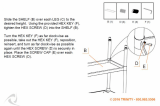
4. Push and hold the right spring-loaded clamp
forward with your thumb.
5. Insert the right tab of the sanding belt in the slot,
pushing all the way in (as far as possible), until it is
tight.
Tip: Use a flat stick or any
similar non-cutting object to
force the tab further into the
slot so it is as tight as
possible.
Note: On occasion, due to slight variations in the length of the sanding belt or the depth of installation in the
left belt clamp, even with the belt properly wound onto the drum, there may be slightly too much belt left at the
right end of the drum. This may cause a slight overlap on the last wrap on the drum, A, and this despite installing
the right end of the belt as far into the clamp as it will go. In such cases, to avoid having to unroll and realign
the entire belt on the drum after it has already been secured at both ends and is otherwise properly installed,
use a utility knife or scissors to cut and remove the overlapped section of paper. To avoid belt tearing during
sanding, avoid cutting at right angles, B, - make a rounded or curved cut, C. (See pictures below.)
A
C
B
6. Release only the first stage of the clamp, sliding
your thumb down towards the bottom to lock the
tab in place.
7. Release the clamp, A. This will bring proper ten-
sion, B, to the sanding belt.
A B

18
8. Once the sanding belt has been properly installed and tensioned on the drum, close and lock the drum cover.
Note: With the sanding belt tab properly inserted in the clamp, the clamp assembly should not pull back more
than 3/4" from the slot in the drum. If the clamp assembly pulls back further than 3/4" the sanding belt tab, A,
needs to be inserted further into the clamp to remove some of the slack in the belt, B. Otherwise the paper will
not be properly tensioned on the drum and the belt may loosen, unwind, or possibly tear when it comes in con-
tact with the workpiece. (See images below.)
A
B
Max.
3/4”
LUBRICATION
DISCONNECT MACHINE FROM POWER SOURCE, BEFORE PERFORMING ANY MAINTENANCE OR LUBRICATION.
Note: Unscrew and remove the front panel, A, and
both side panels, B, to access the conveyor elevation
mechanism.
B
B
Keep threaded rods, C, and gears, D, on both sides of
the machine, greased and free of dust or debris.
Clean and remove dust, debris, and old grease after
every 10-15 hours of use. After cleaning, re-apply a
generous coating of any all purpose grease.
A
D
C
Also keep the conveyor roller drive chain, E, well lubri-
cated. Once a year or as needed, depending on
frequency of use, clean and remove old lubricant
and reapply fresh lubricant as needed. (Use any all-
purpose grease).
Note: To access the chain
drive, unscrew and remove
the chain drive box cover.
E

PERIODIC MAINTENANCE
1. Inspect/test the ON/OFF switches before each use. Do not operate the sander with a damaged switch; replace
a damaged switch immediately.
2. Keep the machine, especially motor and the conveyor clean and free of dust or glue.Vacuum or brush off any
loose debris and wipe down the machine and the conveyor occasionally with a damp rag.
3. The drum must always be kept clean. Dirt on the drum will cause belt slippage.
4. The motor and drum bearings are sealed and permanently lubricated - no further lubrication is required.
5. Periodically inspect the power cord and plug for damage, as well as the sanding belt, the drum, the motor pul-
leys drive belt and the conveyor belt.
NEVER OPERATE THE SANDER WITH ANY DAMAGED PART. REPLACE A DAMAGED PART AT THE FIRST VISIBLE
SIGNS OF DAMAGE.
REQUIRED MAINTENANCE
DRUM MOTOR BEL
T REPLACEMENT
The sanding drum is driven by a belt mounted on two pulleys powered by the motor. If the belt becomes too
loose due to wear or if a breakage occurs, you must replace it as follows:
1. Unscrew and remove both side panels, A.
2. Loosen but do not remove the hex nuts, B, (with the
supplied 14 mm open end wrench), located on
the motor adjustment plate.
A
A
B
PROCEED WITH CAUTION. REMOVING THE BELT FROM THE PULLEY WILL CAUSE THE MOTOR TO SWING FREELY
UNDER IT'S OWN WEIGHT ON THE SUPPORT BRACKET. DO NOT LET IT DROP. HOLD IT UNTIL IT IS BACK DOWN.
3. Lift the motor up with one hand. This will loosen the
belt.
4. With your other hand, carefully remove the belt
from the lower pulley, C.
19
C

We offer a large variety of products to help you increase convenience, productivity, accuracy and safety when
using your sander Here’s a small sampling of optional accessories available from your local General
International dealer.
For more information about our products, please visit our website at www.general.ca
RECOMMENDED OPTIONAL ACCESSORIES
SANDING BELTS
#15-156 - 60 Grit
#15-157 - 80 Grit
#15-158 - 100 Grit
#15-159 - 120 Grit
#15-161 - 150 Grit
#15-162 - 180 Grit
Dust Collector
Dust collectors contribute
to a cleaner and more
healthful workshop envi-
ronment.
We have a wide selection
of dust collectors to suit all
your shop needs.
Mobile base
Item 50-025
Easily roll your sander
anywhere in your shop.
Load capacity: 500 lbs.
Wheels lock when equi-
pment is in use.
Flexible, expandable
2-way roller stand
Item 50-167S
Ideal for use for infeed or
outfeed support. 20” wide,
height from 24 1/4” to 37”,
and length from 21” to 51”.
Four 4” high quality swivel
casters with locking foot
levers. 300 lbs load capa-
city.
20
5. Remove the belt from the upper pulley, D, and
install a new belt.
6. Lift the motor up with one hand and install the
other end of the belt on the lower pulley with the
other hand.
7. Put the motor back to its initial position, then
retighten the hex nuts located on the motor adjust-
ment plate.
D
REPLACING MOTOR
Should the motor require replacement, remove the
4 bolts on the bottom of the motor base plate, E, and
remove the entire motor assembly.
NEVER ATTEMPT TO REPAIR MOTOR YOURSELF.
CONTACT A QUALIFIED TECHNICIAN.
E
Page is loading ...
Page is loading ...
Page is loading ...
Page is loading ...
Page is loading ...
Page is loading ...
Page is loading ...
Page is loading ...
Page is loading ...
Page is loading ...
-
 1
1
-
 2
2
-
 3
3
-
 4
4
-
 5
5
-
 6
6
-
 7
7
-
 8
8
-
 9
9
-
 10
10
-
 11
11
-
 12
12
-
 13
13
-
 14
14
-
 15
15
-
 16
16
-
 17
17
-
 18
18
-
 19
19
-
 20
20
-
 21
21
-
 22
22
-
 23
23
-
 24
24
-
 25
25
-
 26
26
-
 27
27
-
 28
28
-
 29
29
-
 30
30


General International 15-155 M1 Setup & Operation Manual
- Category
- Power sanders
- Type
- Setup & Operation Manual
Ask a question and I''ll find the answer in the document
Finding information in a document is now easier with AI
Related papers
Other documents
-
WALI SBR-201 User manual
-
 TRINITY XBS-03-012-4417 User manual
-
Wen 65910 User manual
-
-
-
Woodstock W1678 User manual
-
 Grizzly Industrial G0716 User manual
-
 Grizzly Industrial G0716 Owner's manual
-
-
Grizzly Industrial G1066R Owner's manual


