
SERVICE
MANUAL
Model 200 Projector

DECLARATION OF CONFORMITY
PER ISO/IEC GUIDE 22 AND EN 45014
Manufacturer: Hughes JVC
2310 Camino Vida Roble
Carlsbad, Ca 92009
USA
Hughes-JVC declares that this product conforms to the following Product
Specifications (Directive/Standard):
Safety: EN 60950
IEC 950 (1992)
EMC: EN 55022 (1988) / CISPR-22 (1986) Class "A"
EN 50082-1 (1992) / IEC 801-2(1991)
EN 50082-1 (1992) / IEC 801-3(1984)
EN 50082-1 (1992) / IEC 801-4(1988)
ANSI C63.4-1992, FCC, Part 15, Class A
In addition, the above product complies with the requirements of the Low
Voltage Directive 73/23 EEC and the EMC Directive 89/336/EEC.
104111 First Edition November 1996
104111 Rev A February 1997
Confidential and proprietary information.
© Copyright 1993 by Hughes-JVC Technology Corporation.
All worldwide rights reserved.
This manual was produced by Hughes-JVC Technology Corporation and may be
revised without prior notice.
No part of this manual may be reproduced in any form without the express
written permission of Hughes-JVC Technology Corporation.
ILA
®
is a registered trademark of Hughes-JVC Technology Corporation.
Model 200 Service Manual
ii

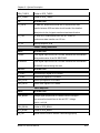
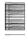
Table of Contents
Safety Information .................................................................................. v
Chapter 1 Introduction
1.1 Acronyms Used in Manual......................................................................... 1-1
1.2 Safety ........................................................................................................ 1-2
1.2 Updates ..................................................................................................... 1-2
1.4 Tool List..................................................................................................... 1-2
Chapter 2 Functional Description
2.1 Introduction................................................................................................ 2-1
2.2 Optical Section .......................................................................................... 2-2
2.3 Electronics System.................................................................................... 2-7
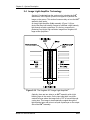
2.4 Image Light Amplifier Technology ............................................................. 2-63
Chapter 3 Service Adjustments
3.1 Arc Lamp Focus and Alignment ................................................................ 3-1
3.2 Arc Lamp Current Setting.......................................................................... 3-4
3.3 Electronic Module Tilt-Up .......................................................................... 3-5
3.4 ILA
®
Back Focus ....................................................................................... 3-5
3.5 CRT Mechanical Focus ............................................................................. 3-7
3.6 CRT Rotation............................................................................................. 3-9
3.7 CRT Electronic Focus ............................................................................... 3-10
3.8 ILA
®
Overlap ............................................................................................. 3-10
3.9 Jumper Settings (Front/Rear or Inverted Vertical)..................................... 3-12
3.10 Vertical and Horizontal Size Settings ........................................................ 3-13
3.11 Software Updating..................................................................................... 3-15
3.12 Cleaning Lenses, ILA
®
Assemblies and Mirrors ....................................... 3-17
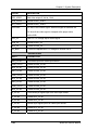
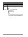
Chapter 4 Maintenance (Removal/Replacement)
4.1 Introduction................................................................................................ 4-1
4.2 Projector Covers........................................................................................ 4-4
4.3 Air Filters ................................................................................................... 4-5
4.4 Arc Lamp Assembly................................................................................... 4-5
4.5 Arc Lamp Power Supply............................................................................ 4-8
4.6 Low Voltage Power Supply........................................................................ 4-8
4.7 High Voltage Power Supply....................................................................... 4-8
4.8 Raster Timing, System Controller, Video Processor PCBs ....................... 4-10
4.9 Convergence/Deflection PCB.................................................................... 4-11
4.10 Horizontal/Vertical Deflection PCB............................................................ 4-12
4.11 Video Input Cards (VICs) .......................................................................... 4-13
4.12 Video Amplifier PCB.................................................................................. 4-14
4.13 Scan Reversal Board ................................................................................ 4-16
4.14 CRT/Yoke Assembly ................................................................................. 4-16
4.15 ILA
®
Assembly .......................................................................................... 4-18
4.16 Relay Lens ................................................................................................ 4-19
4.17 Projection Lens.......................................................................................... 4-20
4.18 Prism Assembly......................................................................................... 4-21
Model 200 Service Manual
iii

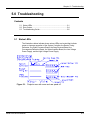
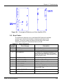
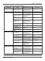
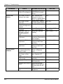
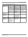
Chapter 5 Troubleshooting
PCB Status LEDs.............................................................................................. 5-1
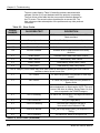
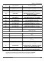
Error Codes ................................................................................................... 5-4
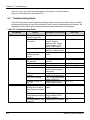
Troubleshooting Guide...................................................................................... 5-5
Chapter 6 Parts List.............................................................................. 6-1
Appendix A Import/Export ...................................................
A-1
Appendix B Glossary
............................................................................ B-1
Model 200 Service Manual
iv
Safety Information
Safety Information
Introduction
Read entire Safety Chapter thoroughly before performing any
maintenance or service on the projector. Only qualified service
personnel should perform procedures and adjustments.
Safety Equipment: Use safety equipment specified in the
projector’s Maintenance training and certification program or
equivalent maintain equipment.
WARNINGS AND CAUTIONS!
Warnings and Cautions in this manual should be read thoroughly
and strictly adhered to. Warning and Caution definitions and
symbols are as follows:
WARNING SYMBOL Warns user of a
potential electric shock hazard in a procedure or situation that
could result in personal injury if improperly performed.
CAUTION SYMBOL Warns user of a
potential safety hazard or potential light hazard from ultraviolet,
infrared or bright light that could cause severe eye injury or a
situation that could result in damage to the equipment if
improperly used.
Model 200 Service Manual
v

Safety Information
Installation Safeguards
WARNING!!! Procedures in this service manual require
removing the projector’s covers to access internal component to
remove, replace, service and adjust the projector. Only Hughes-
JVC Certified Technicians are qualified to perform these
procedures. Before removing or replacing any internal
components or subassemblies, verify that the circuit breaker on
the back panel is in the Off position and remove the power plug.
Any adjustments performed that require covers off and power on
should be performed with extreme care. Be especially aware of
all hazardous areas indicated by warning and caution labels.
CAUTION!!! Do not use a forklift to lift the projector without
using a safe shipping pallet. Lifting the projector without
supporting the weight at the foot locations can cause severe
damage to the projector.
If there is any visible damage to the power cable, disconnect
power to the projector until the damaged cable is replaced. Install
the projector on a smooth, vibration-resistant level surface, or
ceiling mount, in an area free from dust and moisture. Do not
place the equipment in direct sunlight or near heat-radiating
appliances. Smoke, steam and exposure to direct sunlight could
adversely affect the internal components.
If mounting the projector, use hardware that can handle a
minimum of three (3) times the projector weight.
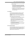
Heat Safeguards
Fans and Ventilation: The projector has multiple fans to cool the
system. Do not block the intake or outflow of any fans. Heat is
emitted within the system and must be properly dissipated to keep
the system running correctly. Blocking air intake or exhaust ports
can lead to projector overheating. Do not enclose the unit in a
restricted space (refer to the physical access and thermal
clearance illustration guidelines).
Model 200 Service Manual
vi

Safety Information
CAUTION! Do not unplug the power cord until after the arc
lamp fan has stopped running. This fan protects the arc lamp from
overheating. Disconnecting power before the cooling fans have
stopped running can shorten Arc Lamp life.
Light Safeguards
Ultra Violet and Infrared Light
Eye and face protection from ultra violet light and infrared light in
accordance with the following conditions:
1. X3 (up to 375 nanometers), ANSI approved, shade
goggles must be worn by anyone near the projector
when it is lit and the cover is off.
2. X5 (375 to 700 nanometers), ANSI approved, shade
goggles when actually working on the projector
near the arc lamp source.
WARNING, BRIGHT LIGHT!!!
Never look directly at the Arc Lamp, the lighted Projection
Lens or into the lamp housing, from any distance, when the
projector is on. Direct exposure to light of this brightness can
cause severe eye injury.
Dangerous levels of ultraviolet and infrared radiation,
dangerous glare, very high temperatures (180°C to 300°C) and
high internal gas pressure are present at the Xenon Arc
Lamp. The lamp is contained in a protective reflector housing
module and should not be operated outside this housing or
outside of the projector. When replacement is needed, the arc
lamp must be replaced as an entire module, as shown in this
Model 200 Service Manual. Do not open the lamp housing or
attempt to replace the Arc Lamp inside its module! Do not
touch the Arc Lamp, or any connections, when the lamp is
ignited or is arcing. Any servicing of the Arc Lamp must
remain restricted to Hughes-JVC certified maintenance
personnel.
Model 200 Service Manual
vii

Safety Information
Electrical Safeguards
WARNING!!! High Voltage points up to 40,000 volts
are exposed inside the covers. Allow at least one minute for
the high voltage to bleed off, even after power is turned off.
High voltage access. Front
and rear covers contain
safety interlocks. Defeat
restricted to Hughes-JVC
certified service personnel!
Due to high voltage danger,
DO NOT TOUCH
• CRT cables. These cables can cause severe shock from a
tiny, invisible crack or hole and should never be touched
while projector power is on.
• CRT anodes.
• Main power ± supply posts.
• Arc Lamp main power ± posts.
• CRT yoke assemblies and other proximity electrical
assemblies, components and wiring. If performing the ILA
®
Back Focus, CRT Mechanical Focus, CRT rotation, or
ILA
®
Overlap adjustment, as outlined in Chapter 3, always
use an ANSI/ASTM 10,000 volt rated glove. Periodically
check the condition of the gloves for cracks.
Power Supply
The projector operates from a 100V - 240V, 20 Amp, single-
phase, 50/60 Hz AC power source. Ensure local power source
matches these requirements before operating!
For continued safe and reliable operation, only use cables
supplied by the manufacturer for power and signal connections.
Fluid Safeguards
Certain components of the projector contain fluid. If any fluid from
the projector contacts the skin, wash off with soap and water. If
any fluid from the projector splashes into the eyes, rinse with cool
running water.
Model 200 Service Manual
viii

Safety Information
Ventilation and Foreign Object Retrieval
CAUTION! Ensure projector’s multiple fans are free from
obstructions and operating properly. Air filters are located at vent
ports on the cover. Air filters require periodic cleaning to ensure
adequate cooling of the projector (Section 4.3). Ensure that all
vent ports are clear of obstructions.
Keep the inside of the projector free from foreign objects, such as
hairpins, nails, paper, etc. Do not attempt to retrieve any object or
insert metal objects such as wire and screwdrivers inside the unit.
If an object falls inside the projector, immediately unplug the
projector and call a Hughes-JVC certified technician to remove
object.
Model 200 Service Manual
ix

Safety Information
Model 200 Service Manual
x

Chapter 1---Introduction
1.0 Introduction
This Service Manual is designed to be used with the Model 200
User’s Guide. This service manual provides information on the:
— Projector functional description;
— Service adjustments, removal and replacement of
subassemblies; and
— Troubleshooting.
The user’s guide covers the projector’s installation, operation,
setup adjustments, and specifications. Together the service
manual and user’s guide provide a qualified service person with
information to operate and maintain the projector.
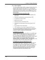
1.1 Safety
This projector contains high voltages and high intensity light
sources in its internal system and power supplies. Read entire
Safety Chapter at the front of this manual before performing any
adjustments or maintenance.
When performing procedures that call for projector’s power to be
on, always wear high voltage gloves (ANSI/ASTM 10,000 volt
rated) when working around the CRTs, Arc Lamp or power
supplies. Wear safety goggles (rated X5) when working anywhere
near the light path from the Arc Lamp or the projection lens at all
times.
1.2 Updates
Hughes-JVC will periodically provide bulletin and /or manual
supplements to ensure the accuracy of this service manual.
1.3 Tool List
The following tools are required to perform service adjustments:
All Purpose Tools=Diagonal Sidecutters, Wirestrippers,
Slot Adjustment Screwdriver (Tweeker),
Mirror/Magnet Pick-Up Tool, Flashlight, 6” Crescent
Wrench, Needlenose pliers, 6” Vise Grips
Balldriver, 1.5mm
Balldriver, 3mm
Balldriver, 3mm, Long
Balldriver, 4mm
Balldriver, 5mm, Long, T-handle
Balldriver, 6mm
Model 200 Service Manual 1-1

Chapter 1---Introduction
Balldriver, 8mm
Ballpoint L-Wrench Set, 1.5-5mm
Delrin .100 Hex Alignment Tool
Gloves, ANSI/ASTM 10,000 volt rated, Safety
Goggles, Safety, x3(covers on) and x5(covers off)
Hex Ballpoint Driver, 3mm
Hex Ballpoint Driver, 5mm
Nutdriver, 10mm
Nutdriver, 11mm (or 7/16”)
Nutdriver, 5mm
Nutdriver, 7mm
Nutdriver, 8mm
Screwdriver, Phillips, #1
Screwdriver, Phillips, #2
Screwdriver, Pozidrive, #1
Screwdriver, Pozidrive, #2
Screwdriver, Slot ¼”
Screwdriver, Slot, ½”
Screwdriver, Slot, 3/16”
Socket, ¼” drive, 7mm-deep
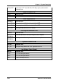
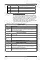
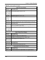
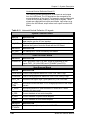
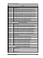
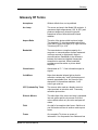
1.4 Acronyms Used in this Manual
ALPS Arc Lamp Power Supply
CDB Convergence/Deflection Board
CH Channel
CPU Central Processing Unit
CRT Cathode Ray Tube
EMI Electromagnetic Interference
FLASH Erasable Programmable Read-Only Memory
EPROM
FPGA Field Programmable Gate Array
F to V Frequency to Voltage
G2 CRT Grid 2
HVDB Horizontal/Vertical Deflection Board
HDTV High Definition Television
Hz Hertz
HSYNC Horizontal Sync
HVDB Horizontal/Vertical Deflection Board
HVPS High Voltage Power Supply
IIC Inter-Integrated Circuit
ILA
®
Image Light Amplifier
I/O Input/Output
I/R Infrared
kHz Kilohertz
LED Light Emitting Diode
LVPS Low Voltage Power Supply
NTSC National Television Standards Committee
PAL Phase Alternating Line
PCB Printed Circuit Board
PLL Phase Lock Loop
1-2 Model 200 Service Manual

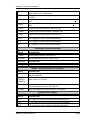
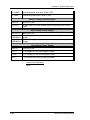
Chapter 1---Introduction
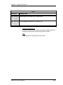
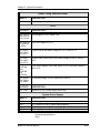
PLUGE Picture Line-Up Generating Equipment
RAM Random Access Memory
RGB Red, Green and Blue
RGBHV Red, Green, Blue, Horizontal, Vertical
ROM Read Only Memory
RTG Raster Timing Generator
SCB System Controller Board
SECAM Sequential couleur a memoire (sequencial
color with memory
SRB Scan Reversal Board
SYNC Synchronization
TTL Transistor-Transistor Logic
UL Underwriter Laboratories
UV Ultraviolet
VAB Video Amplifier Board
VCO Voltage Controlled Oscillator
VIC Video Input Card
VIN Video Input
VPB Video Processor Board
VSYNC Vertical Sync
VTR Video Tape Recorder
YC Luminance/Chrominance
Model 200 Service Manual 1-3

Chapter 1---Introduction
1-4 Model 200 Service Manual

Chapter 2---System Description
2.0 System Description
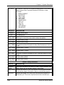
Contents
2.1 Introduction .............................................................................. 2-1
2.2 Optical System......................................................................... 2-2
2.2.1 Image Path................................................................... 2-2
2.2.2 Arc Lamp Light Path .................................................... 2-4
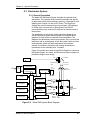
2.3 Electronics System .................................................................. 2-7
2.3.1 General Description ..................................................... 2-7
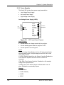
2.3.2 Power Supplies ............................................................ 2-8
2.3.3 Video Input Cards ........................................................ 2-14
2.3.4 Video Processor PCB .................................................. 2-24
2.3.5 Video Amplifier PCB .................................................... 2-30
2.3.6 System Controller PCB ................................................ 2-34
2.3.7 Raster Timing Generator PCB ..................................... 2-40
2.3.8 Horizontal/Vertical Deflection PCB .............................. 2-45
2.3.9 Convergence/Deflection PCB ...................................... 2-51
2.3.10 Scan Reversal PCB ..................................................... 2-57
2.3.11 Backplane PCB............................................................ 2-62
2.4 Image Light Amplifier Technology ........................................... 2-63
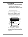
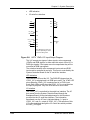
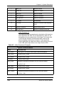
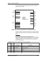
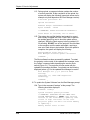
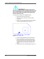
2.1 Introduction
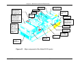
The assemblies and components in the Model 200 projector are
contained mainly in the five sections below:
• The Optics Assembly Section is located at the front area of
the projector. The Optics Assembly Section includes the
Condensing Lens, Cold Mirror/IR Filter (
CAUTION!: The term "cold mirror" is used because
the mirror passes infrared light and its reflection contains only
"cold' light that does not transmit appreciable heat. As a result
of the absorption of infrared heat radiation, "cold" mirrors can
get very hot.), Ultraviolet Filter, Dichroic Mirror Assembly,
Prisms, Combining Prism, Image Mirrors, and the Zoom
Projection Lens.
• The Arc Lamp Assembly section is located in the right front
area of the unit. It contains the Ignitor, Laser Power Supply,
Xenon Arc Lamp and Elliptical Reflector.
Model 200 Service Manual 2-1

Chapter 2---System Description
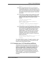
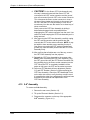
• The Power Supply Section is located at the right front area of
the projector below and to the rear of the Arc Lamp. It contains
the Low Voltage Power Supply, the High Voltage Power
Supply, and the Arc Lamp Power Supply.
• The Projector Electronics Section is located mainly in the
back half of the projector. It consists of the Electronics Module
that houses 6 of the electronics printed circuit boards used in
the projector, and their associated cabling. It also contains the
Backplane board which is used to electrically interconnect the
printed circuit boards, power supplies and various other units
in the projector and the Video Input Cards that interface with
different kinds of input signals.
• The CRT Section is located beneath the electronics card cage
and contains the 3 CRTs, 3 Relay Lenses, 3 ILA
®
s and the
Video Amplifier Board.
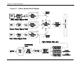
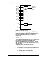
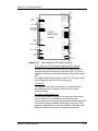
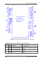
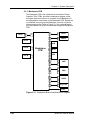
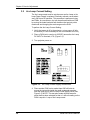
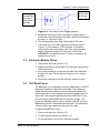
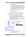
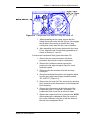
2.2 Optical System
Introduction: The Model 200 Optics Assembly divides white light
from the Arc Lamp into its three color components, Red, Green
and Blue. This light is then modulated with the image signal to
form three single color images. The light is then recombined at the
4P (combining) prism and transmitted through the projection lens
to the projector screen. The explanation below is divided into two
sections. The first section follows the image path from the CRT to
the projector screen. The second section follows the high intensity
light path from the Arc Lamp Ignitor to the ILA
®
assemblies, where
it combines with the image. The Red, Green, and Blue image and
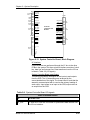
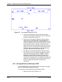
light paths are identical. Refer to Figure 2-1.
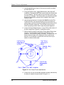
CAUTION! The alignment of system optical
components is critical. Replacement of individual mirrors or prisms
requires removing the projector cover and must be performed only
by Hughes-JVC Certified technicians. Consult the factory before
removing or aligning any mirrors or prisms.
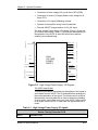
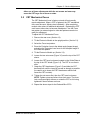
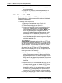
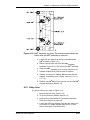
2.2.1 Image Path
CRT Assemblies: The three CRT/Yoke assemblies are located
beneath the Electronics Module card cage. Two exhaust fans at
the rear help cool the CRT assemblies. Each CRT is sent a red,
green, or blue signal, but they do not emit a red, green, or blue
color, as in traditional projectors. The CRTs are not used as a
2-2 Model 200 Service Manual

Chapter 2---System Description
primary light source. The light output to the screen is the function
of the Arc Lamp. The purpose of the CRTs is to generate an
image and to control the amount of modulation the ILA
®
assemblies introduce on the light coming from the Arc Lamp. The
Red, Green, and Blue image signals are routed to the CRTs from
the Video Amplifier Board through the CRT socket connectors.
Relay Lens: The relay lens picks up the image from the face of
the CRT and focuses the image to the ILA
®
assembly.
Image Light Amplifier (ILA
®
) Assembly: The CRT image is
received from the relay lens onto the input side of the ILA
®
assembly. The input and output sides of the ILA
®
assembly are
isolated from each other electrically and optically but are coupled
electrostatically.
At the same time as the image is received at the input side of the
ILA
®
assembly, the output side of the ILA
®
assembly is receiving
high intensity light from the arc lamp through the prism. This high
intensity light is modulated (changing its polarization) by the signal
on the input side of the ILA
®
assembly. The light is then reflected
back from the output side of the ILA
®
assembly, then travels
through the prism to be picked up by the projection lens.
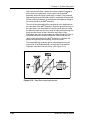
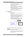
NOTE: The prism reflects horizontally polarized light and passes
vertically polarized light. Light from the arc lamp is polarized
horizontally and reflects from the prism into the ILA
®
assembly
then back out again, after being modulated by the image signal
into vertically polarized light. The vertically polarized light then
passes through the prism to the projector lens. In this manner the
ILA
®
assembly combines the image from the CRT with the high
intensity light from the arc lamp. Thus, the maximum brightness of
the screen image is not dependent on the brightness of the CRT,
but on the light from the arc lamp.
For a more detailed description of how the ILA
®
assembly works,
refer to Section 2.7 below.
Polarizing Prism: The polarizing prism receives the high intensity
light from the xenon arc lamp and polarizes the light horizontally.
The prism reflects virtually all of this light toward the ILA
®
assembly. This light is then modulated (altered) into a vertical
plane by the image on the input side of the ILA
®
assembly and
then reflected back into the same prism. Since the prism reflects
only horizontal light and passes vertical light, this high intensity,
vertically polarized image goes straight through the prism toward
the Combining Prism. Light that is not completely polarized
horizontally or vertically passes through the prism in varying
degrees of brightness, according to how polarized it is (fully
polarized light resulting in maximum brightness on the screen).
Image Mirror: The Image Mirrors direct the blue and red images
toward the Combining Prism.
Model 200 Service Manual 2-3

Chapter 2---System Description
Combining (4P) Prism: The combining prism consists of
separate prisms that polarize each of the three high intensity
signals and direct them toward the projection lens.
Projection Lens: The Projection Lens picks up the high intensity
image from the Combining Prism and transmits it to the projector
screen.
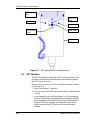
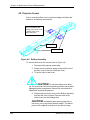
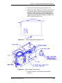
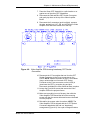
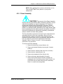
2.2.2 Arc Lamp Light Path
The Arc Lamp assembly produces the high intensity light used to
transmit bright images to the screen. It consists of a Xenon Arc
Lamp containing xenon gas under pressure, an ignitor assembly
that provides the spark to light the arc lamp, and a laser power
supply to provide the boost voltage to the Ignitor. An exhaust fan
helps keep the arc lamp cool. The description below follows the
sequence of the light path. (See Figure 2-1).
Ignitor and Laser Power Supply: The Laser Power Supply
provides a boost voltage through a spark gap to the Ignitor circuit
which then provides a momentary High Voltage, (32,000 volts), to
excite the xenon gases inside the Xenon Arc Lamp. After the arc
lamp ignites, it is maintained ON by high current and low-voltage
(approximately 37.5 amps and +20 volts). The arc lamp Ignitor
and Laser Power Supply are mounted next to the arc lamp, inside
the Arc Lamp assembly housing.
WARNING!!! The Xenon Arc Lamp produces high
intensity white, ultraviolet and infrared light capable of severe eye
injury. Never look directly at or touch the Xenon Arc Lamp.
Service should be performed by Hughes-JVC certified
technicians only.
Xenon Arc Lamp/Condensing Lens: High pressure, ionized
xenon gas supports a high-current electrical arc to produce the
intense, white light used in the Model 200 projector. The high
intensity light output from the Xenon Arc Lamp is reflected by an
elliptical metal reflector to a Condensing Lens where the light
beam is condensed and directed to the Cold Mirror.
Cold Mirror/IR Filter and Ultraviolet Filter: The arc lamp light
beam passes through the Condensing Lens to the Cold Mirror and
Infrared Filter which removes most of the IR light, then through the
Ultraviolet filter which removes most of the UV light. The light
beam then proceeds toward the Dichroic Mirror Assembly. In this
manner most of the IR and UV light is filtered out before the light
beam enters the more sensitive portions of the optics, leaving only
the visible portion.
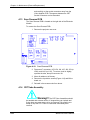
Dichroic Mirror Assembly: The condensed and filtered white
light beam enters the Dichroic Mirror Assembly which separates
(dichroic mirrors reflect only one color and pass all others) the
2-4 Model 200 Service Manual

Chapter 2---System Description
light into its Red, Green and Blue components. The first mirror in
the Dichroic Mirror Assembly reflects blue light to the blue ILA
®
assembly, the second mirror reflects green light to the green ILA
®
assembly, and the third reflects red light to the red ILA
®
assembly.
Thus, each ILA
®
is sent only one color of light.
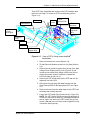
Prepolarizers and Polarizing Prisms: Each individual light beam
is polarized (directed) toward its own Polarizing Prism where it is
directed toward the output side of its ILA
®
Assembly and
combined with the signal from the input side of the ILA
®
Assembly.
Each of these three light beams independently combine with the
image in their own (Red, Green or Blue) color systems at the ILA
®
assemblies as described in Section 2.2.1, Image Path.
Model 200 Service Manual 2-5

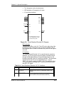
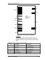
Chapter 2---System Description
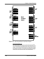
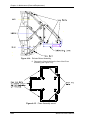
Figure 2-1. Optical System Block Diagram
2-6 Model 200 Service Manual
Page is loading ...
Page is loading ...
Page is loading ...
Page is loading ...
Page is loading ...
Page is loading ...
Page is loading ...
Page is loading ...
Page is loading ...
Page is loading ...
Page is loading ...
Page is loading ...
Page is loading ...
Page is loading ...
Page is loading ...
Page is loading ...
Page is loading ...
Page is loading ...
Page is loading ...
Page is loading ...
Page is loading ...
Page is loading ...
Page is loading ...
Page is loading ...
Page is loading ...
Page is loading ...
Page is loading ...
Page is loading ...
Page is loading ...
Page is loading ...
Page is loading ...
Page is loading ...
Page is loading ...
Page is loading ...
Page is loading ...
Page is loading ...
Page is loading ...
Page is loading ...
Page is loading ...
Page is loading ...
Page is loading ...
Page is loading ...
Page is loading ...
Page is loading ...
Page is loading ...
Page is loading ...
Page is loading ...
Page is loading ...
Page is loading ...
Page is loading ...
Page is loading ...
Page is loading ...
Page is loading ...
Page is loading ...
Page is loading ...
Page is loading ...
Page is loading ...
Page is loading ...
Page is loading ...
Page is loading ...
Page is loading ...
Page is loading ...
Page is loading ...
Page is loading ...
Page is loading ...
Page is loading ...
Page is loading ...
Page is loading ...
Page is loading ...
Page is loading ...
Page is loading ...
Page is loading ...
Page is loading ...
Page is loading ...
Page is loading ...
Page is loading ...
Page is loading ...
Page is loading ...
Page is loading ...
Page is loading ...
Page is loading ...
Page is loading ...
Page is loading ...
Page is loading ...
Page is loading ...
Page is loading ...
Page is loading ...
Page is loading ...
Page is loading ...
Page is loading ...
Page is loading ...
Page is loading ...
Page is loading ...
Page is loading ...
Page is loading ...
Page is loading ...
Page is loading ...
Page is loading ...
Page is loading ...
Page is loading ...
Page is loading ...
Page is loading ...
Page is loading ...
Page is loading ...
Page is loading ...
Page is loading ...
Page is loading ...
Page is loading ...
Page is loading ...
Page is loading ...
Page is loading ...
Page is loading ...
Page is loading ...
Page is loading ...
Page is loading ...
Page is loading ...
Page is loading ...
Page is loading ...
Page is loading ...
Page is loading ...
-
 1
1
-
 2
2
-
 3
3
-
 4
4
-
 5
5
-
 6
6
-
 7
7
-
 8
8
-
 9
9
-
 10
10
-
 11
11
-
 12
12
-
 13
13
-
 14
14
-
 15
15
-
 16
16
-
 17
17
-
 18
18
-
 19
19
-
 20
20
-
 21
21
-
 22
22
-
 23
23
-
 24
24
-
 25
25
-
 26
26
-
 27
27
-
 28
28
-
 29
29
-
 30
30
-
 31
31
-
 32
32
-
 33
33
-
 34
34
-
 35
35
-
 36
36
-
 37
37
-
 38
38
-
 39
39
-
 40
40
-
 41
41
-
 42
42
-
 43
43
-
 44
44
-
 45
45
-
 46
46
-
 47
47
-
 48
48
-
 49
49
-
 50
50
-
 51
51
-
 52
52
-
 53
53
-
 54
54
-
 55
55
-
 56
56
-
 57
57
-
 58
58
-
 59
59
-
 60
60
-
 61
61
-
 62
62
-
 63
63
-
 64
64
-
 65
65
-
 66
66
-
 67
67
-
 68
68
-
 69
69
-
 70
70
-
 71
71
-
 72
72
-
 73
73
-
 74
74
-
 75
75
-
 76
76
-
 77
77
-
 78
78
-
 79
79
-
 80
80
-
 81
81
-
 82
82
-
 83
83
-
 84
84
-
 85
85
-
 86
86
-
 87
87
-
 88
88
-
 89
89
-
 90
90
-
 91
91
-
 92
92
-
 93
93
-
 94
94
-
 95
95
-
 96
96
-
 97
97
-
 98
98
-
 99
99
-
 100
100
-
 101
101
-
 102
102
-
 103
103
-
 104
104
-
 105
105
-
 106
106
-
 107
107
-
 108
108
-
 109
109
-
 110
110
-
 111
111
-
 112
112
-
 113
113
-
 114
114
-
 115
115
-
 116
116
-
 117
117
-
 118
118
-
 119
119
-
 120
120
-
 121
121
-
 122
122
-
 123
123
-
 124
124
-
 125
125
-
 126
126
-
 127
127
-
 128
128
-
 129
129
-
 130
130
-
 131
131
-
 132
132
-
 133
133
-
 134
134
-
 135
135
-
 136
136
-
 137
137
-
 138
138
-
 139
139
-
 140
140


Ask a question and I''ll find the answer in the document
Finding information in a document is now easier with AI