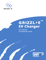
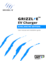
Grizzl-E GRIZZL-E GR1-6-24-R Electric Vehicle Charger User manual
- Type
- User manual
This manual is also suitable for
Grizzl-E GRIZZL-E GR1-6-24-R Electric Vehicle Charger is a heavy-duty, portable EV charging station made in Canada and built to withstand harsh conditions. It provides up to 9.6 kW of power with an adjustable maximum current of 40A, 32A, 24A, or 16A to support multiple circuit ratings. The charger features an airtight aluminum enclosure for indoor or outdoor use, a Plug-in configuration for easy portability, and a security pin for theft protection. The EasyEvPlug holster with cable management system keeps the cable organized and prevents tangles.
Grizzl-E GRIZZL-E GR1-6-24-R Electric Vehicle Charger is a heavy-duty, portable EV charging station made in Canada and built to withstand harsh conditions. It provides up to 9.6 kW of power with an adjustable maximum current of 40A, 32A, 24A, or 16A to support multiple circuit ratings. The charger features an airtight aluminum enclosure for indoor or outdoor use, a Plug-in configuration for easy portability, and a security pin for theft protection. The EasyEvPlug holster with cable management system keeps the cable organized and prevents tangles.


-
 1
1
-
 2
2
-
 3
3
-
 4
4
-
 5
5
-
 6
6
-
 7
7
-
 8
8
-
 9
9
-
 10
10
-
 11
11
-
 12
12
-
 13
13
-
 14
14
-
 15
15
-
 16
16
-
 17
17
-
 18
18
-
 19
19
-
 20
20
-
 21
21
-
 22
22
-
 23
23
-
 24
24
-
 25
25
-
 26
26


Grizzl-E GRIZZL-E GR1-6-24-R Electric Vehicle Charger User manual
- Type
- User manual
- This manual is also suitable for
Grizzl-E GRIZZL-E GR1-6-24-R Electric Vehicle Charger is a heavy-duty, portable EV charging station made in Canada and built to withstand harsh conditions. It provides up to 9.6 kW of power with an adjustable maximum current of 40A, 32A, 24A, or 16A to support multiple circuit ratings. The charger features an airtight aluminum enclosure for indoor or outdoor use, a Plug-in configuration for easy portability, and a security pin for theft protection. The EasyEvPlug holster with cable management system keeps the cable organized and prevents tangles.
Ask a question and I''ll find the answer in the document
Finding information in a document is now easier with AI
Related papers
-
Grizzl-E GRIZZL-E GR1-6-18-R EV Charger Installation guide
-
 Grizzl-E GRIZZL-E GR1-6-18-R Electric Vehicle Charger User manual
-
 Grizzl-E GRIZZL-E GRS-14-24-AW Smart Avalanche Edition EV Charger User manual
-
Grizzl-E DUO EV Charger User manual
-
 Grizzl-E Mini EV Charger User manual
-
Grizzl-E Grizzl-E ChargeLab App User manual


Other documents
-
 YITAHOME SHMYD-V1 User manual
-
 YITAHOME SHMYD-V1 User manual
-
INVT EVC Series User manual
-
 MASSIMO ELECTRIC Y480032711 User manual
-
LECTRON LECHG5-15-15ABLKUS User manual
-
 MEGEAR EVSE User manual
-
METRON PC04T User manual
-
 METRON PC05T User manual
-
 Phillips & Temro Industries EVOCHARGE iEVSE User manual
-
Vision iM3C Series User manual


