Samsung MWR-SH00 Installation guide
- Category
- Split-system air conditioners
- Type
- Installation guide
This manual is also suitable for

Air conditioner
Installation manual
Wired remote controller MWR-SH00N
࡛ Thank you for purchasing this Samsung Product.
࡛ Before operating this unit, please read this installation manual carefully and retain it for future
reference.
DB68-04148A-02

ENGLISH-2
Contents
Preparation
Safety Precautions . . . . . . . . . . . . . . . . . . . . . . . . . . . . . . . . . . . . . . . . . . . . . . . . . . . . . . . . . . . . . . . . . . . . . . . . . . . . . . . . . . . . . . . . . . . . . . . . . . . . . . . 3
Before installation ....................................................................................................... 5
Installation
Wired Remote Controller Installation ..................................................................................... 6
Others
Wired Remote Controller Installation/Service Mode ..................................................................... 15
The lowest set temperature is limited to 20 degree in the UAE according to UAE.S 5010-5:2016.

ENGLISH-3
01 PREPARATION
Safety Precautions
This installation manual explains how to install a Wired Remote Controller connected to the indoor unit of your Samsung
system air conditioner. Please read this manual thoroughly before installing the product.
(Please refer to appropriate installation for any optional product installation.)
WARNING
Hazards or unsafe practices that may result in severe personal injury or death.
CAUTION
Hazards or unsafe practices that may result in minor personal injury or property
damage.
WARNING
Contact a service center for installation.
f Potential risk of malfunction, water leak, electric shock and re.
Install the product with proper power supply.
f Potential risk of re or product damage.
Consult the place of purchase or a contact center to disassemble or repair the product.
f Potential risk of malfunction, electric shock, or re.
The electric work must be done by qualied person according to national wiring regulations and installation guide.
f If an unauthorized person performs the installation, any resulting defects can cause malfunctions, electrical shocks, or re
accidents.
Install the product on a hard and even place that can support its weight.
f If the place cannot support its weight, the product may fall down and it may cause product damage.
Do not move or reinstall the product on your discretion.
f Potential risk of electric shock or re.
Check if the installation work is done correctly according to the installation manual.
f Incorrect installation may cause electric shock or re.
When you want to dispose your Wired Remote Controller, ask the service center.

ENGLISH-4
Safety Precautions
CAUTION
Do not install the product where there’s combustible gas.
f Potential risk of re and explosion.
Ensure no water gets into the Wired Remote Controller.
f Potential risk of electric shock or re.
Install the air conditioner away from direct exposure to sunlight, in room temperature range of
0 °C(32 °F) ~ 39 °C(102 °F).
f Potential risk of electric shock or malfunction.
Do not handle the product with sharp objects.
f Potential risk of electric shock or product damage.
Do not install the product in areas exposed to oil or vapor.
f Potential risk of product damage or malfunction.
Do not put undue stress on the power cable.
f Potential risk of broken cable and re.
Do not install the product in areas with frequent use of acid or alkali spray.
f Potential risk of electric shock or product malfunction
Do not connect power cable to a communication terminal.
f Potential risk of re.
Be cautious not to interfere any other electrical devices if the product is installed in a place such as hospital.
f Potential risk of product malfunction.
ENGLISH-5
01 PREPARATION
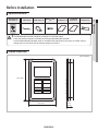
Before installation
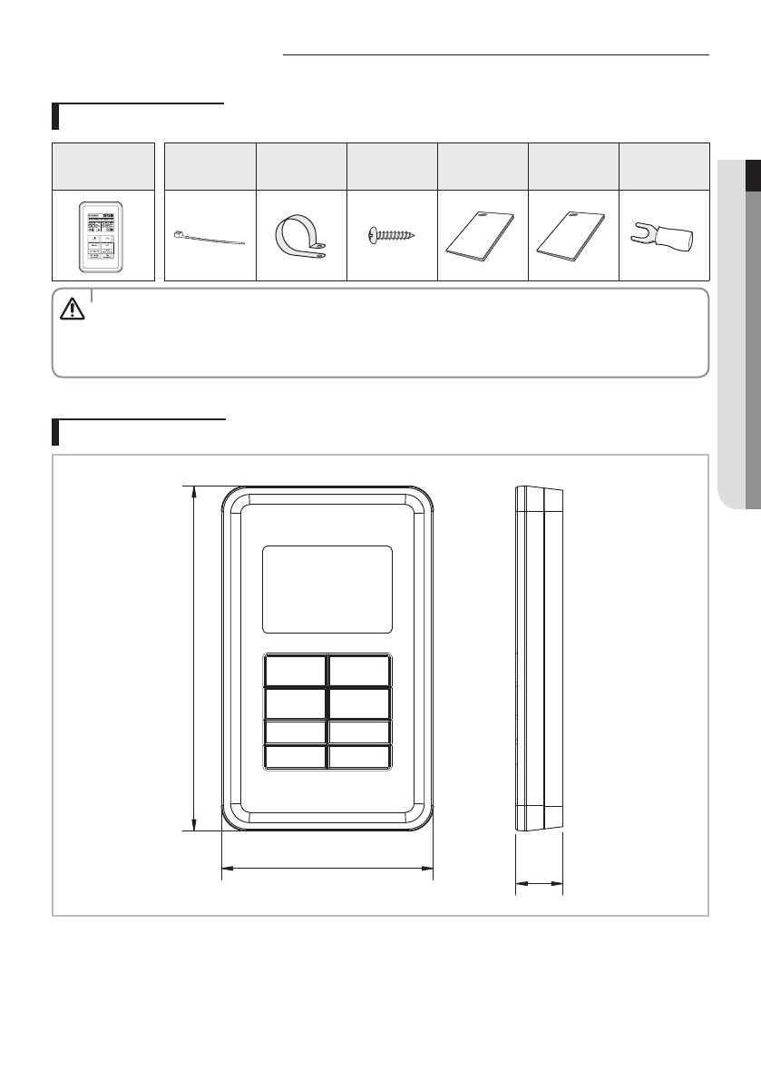
Optional accessories
Wired Remote
Controller (1)
Cable Tie (2) Cable Clamp (2)
M4X16 Screw
(2)
User Manual (1)
Installation
Manual (1)
U Terminal (3)
t The Wired Remote Controller should be installed by an installation expert.
t Check and conrm the power is o before installing your Wired Remote Controller.
t Install the Wired Remote Controller cables in accordance with the electrical wiring rules, and allow it to pass
through the inner area of the wall so that other people can’t reach it.
CAUTION
External Dimensions
[Unit : mm(inch)]
122.0 (4.80)
75.0 (2.95)
16.6
(0.65)
ENGLISH-6
Wired Remote Controller Installation
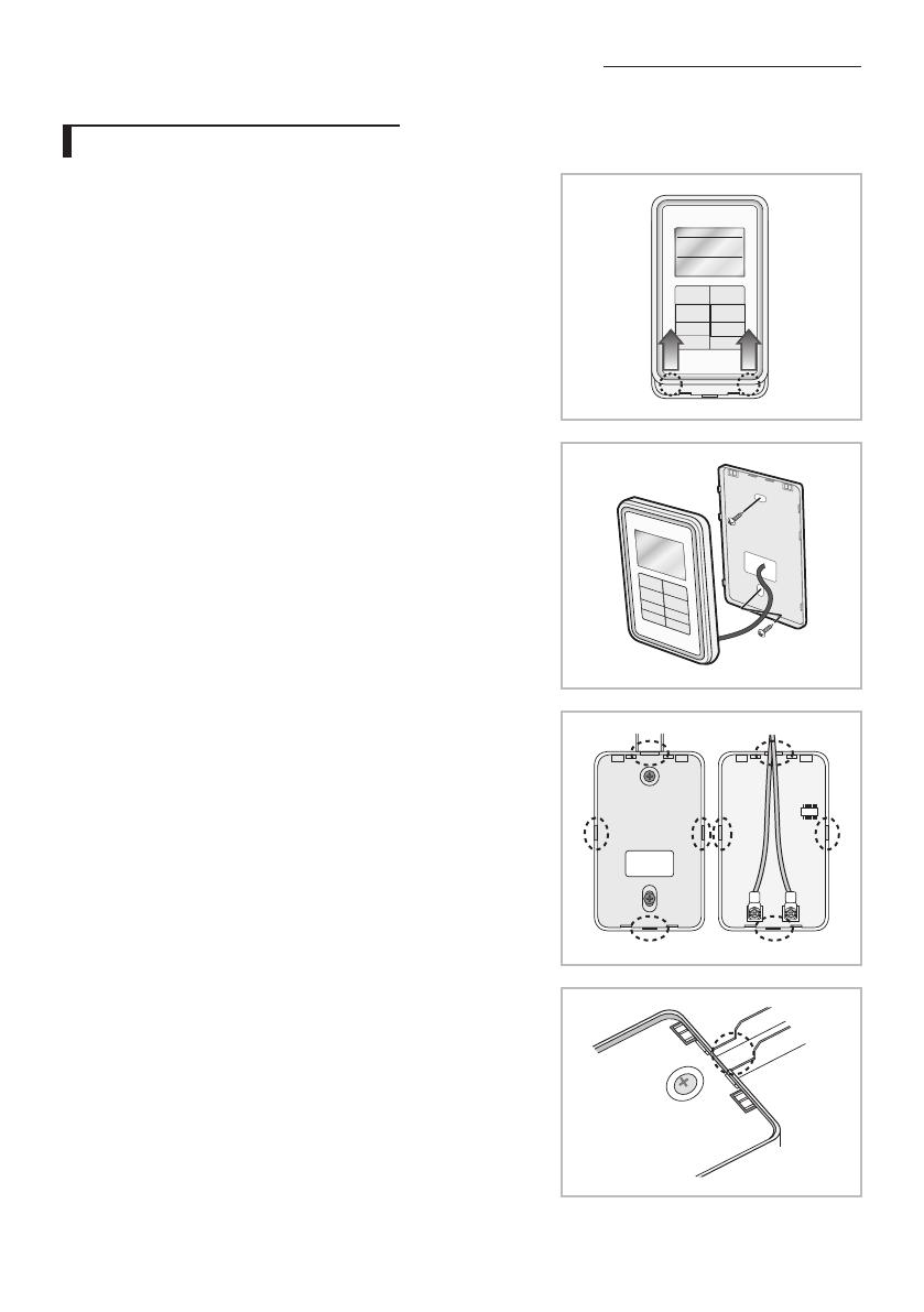
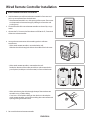
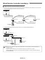
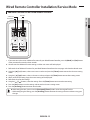
Wired remote controller installation
1. Hold the bottom part of the wired remote controller’s front cover and
push it up to separate it from the back cover.
- Wired remote controller has a slide-open type front cover. (Front cover
can be opened and removed simply by holding the front cover and
pushing it up)
2. Fix the Back cover of the wired remote controller on the wall by using 2
screws.
3. Connect the F3, F4 terminal of the indoor unit PCB to the F3, F4 terminal
of the wire remote controller.
4. Arrange the communication cable according to the installation
environment.
- When wired remote controller is concealed to the wall:
Withdraw the cable through the hole in the middle of the back cover.
- When wired remote controller is mounted on the wall:
Decide the direction of the cables to withdraw and remove the thin
part of plastic (circled part in the illustration) in front and back cover.
- When withdrawing the cable through the top of the wired remote
controller using a cable molding:
Cut at least 1 cm of cable molding on the side that is closed to the
wired remote controller, so that cable molding does not interfere with
opening/closing of the front cover.
5. Re-assemble the wired remote controller.
ENGLISH-7
02 INSTALLATION
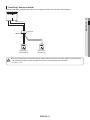
t When installing a Wired Remote Controller by using a cable longer than 10 m(32.80 ft), you must install the
communication cable and the AC power cable separately. (Electrical interference can cause your Wired Remote
Controller to malfunction.)
t When installing your Wired Remote Controller on the wall, consider the size of the wire hole, and select a wire
with a proper thickness.
t Wire that is connectable to Wired Remote Controller PCB.
- If you install the Wired Remote Controller by reclaiming, install it according to U-terminal cable specication.
- If you install the Wired Remote Controller by using two pieces of PVC wire, remove the 30 cm(12 inch) of the
sheath of the cable and install it only with the two pieces of wires. (Recommended specication: AWG20)
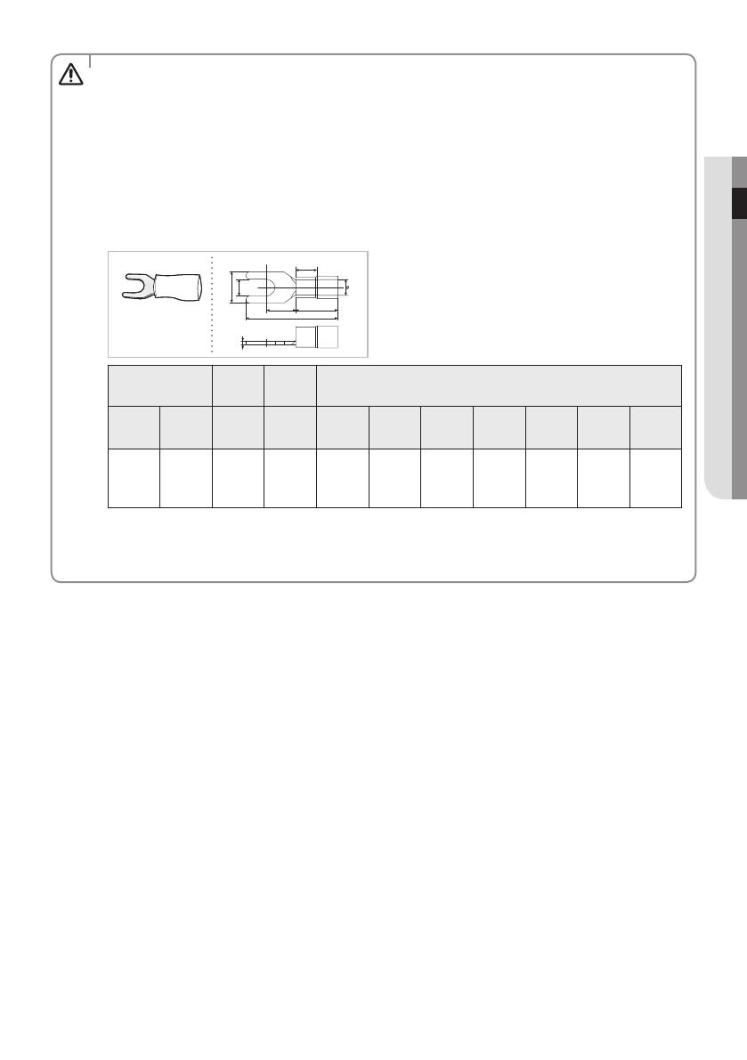
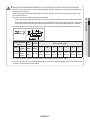
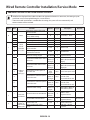
t The following are the specs of the compression ring terminal connected to your Wired Remote Controller PCB.
t 4DSFXTPOUIF1$#UFSNJOBMNVTUCFUJHIUFOFEXJUIMFTTUIBO/tDNUJHIUFOJOHUPSRVF*GUIFUJHIUFOJOHUPSRVF
is greater, it may damage the screw thread.
❋ Maximum distance for connecting communication and power cable: 100 m(3.280 ft)
CAUTION
Range of Permitted
Wires
Rated
Size
Stud Size Basic Size [mm (inch)]
AWG
mm
2
(inch
2
)
mm
2
(inch
2
)
mm
(inch)
tøDG E FWL
22~16
0.25~1.65
(0.0003 ~
0.0025)
1.5
(0.0023)
3 (0.1181)
0.7
(0.0275)
3.8
(0.1496)
10.0
(0.3937)
4.5
(0.1771)
6.5
(0.2559)
6.0
(0.2362)
21.2
(0.8346)
ENGLISH-8
Wired Remote Controller Installation
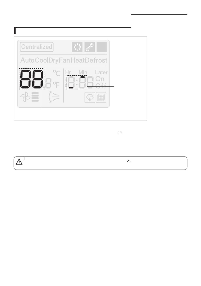
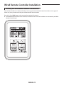
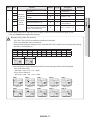
Tracking Your Indoor Unit from the Wired Remote Controller
Displays the total number of units searched
Indicates tracking in
progress
1. Tracking of your Wired Remote Controller will automatically start when you turn on the power after installation.
2. If you want to perform tracking again after installation, then press the [
] and [Set] buttons at the same time for more
than ve seconds.
- The system will reset, and tracking will start again.
3. During tracking, the total number of currently searched indoor units will be displayed.
4. It may take about 5 minutes at initial installation or when you re-set the Power Master setting.
t If you want to perform tracking again after installation, then press the [ ] and [Set] buttons at the same time
for more than ve seconds.
CAUTION

ENGLISH-9
02 INSTALLATION
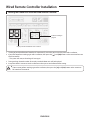
Individual Control with Your Wired Remote Controller
Individual control means that you are using one remote controller to control one indoor unit.
Outdoor Unit
Indoor Unit
COM1(F1, F2)
COM2(F3, F4)
COM1(F1, F2)
COM2(F3, F4) COM2(F3, F4)
Wired Remote
Controller
Wired Remote
Controller
Wired Remote
Controller
Indoor Unit Indoor Unit
t Regardless of the indoor group address (RMC address) only the indoor unit connected to COM2 is individually
controlled.
CAUTION
ENGLISH-10
Wired Remote Controller Installation
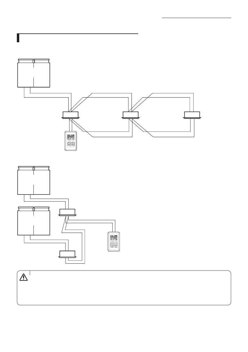
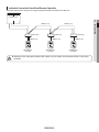
Group Control with Your Wired Remote Controller
Group control means that you are using one Wired Remote Controller to control two or more indoor units at the same time.
1. Using One Wired Remote Controller to control three indoor Units
Outdoor Unit
COM1(F1, F2) COM1(F1, F2)
Wired Remote
Controller
COM2(F3, F4) COM2(F3, F4)
COM1(F1, F2)
Indoor Unit Indoor Unit Indoor Unit
2. Using One Wired Remote Controller to control indoor units connected to dierent outdoor unit
Outdoor Unit
Indoor Unit
Indoor Unit
Wired Remote
Controller
Outdoor Unit
COM1(F1, F2)
COM2(F3, F4)
COM1(F1, F2)
COM2(F3, F4)
t Regardless of the indoor unit’s group address (RMC address), only the indoor units connected to COM2 are
controlled in group.
t Regardless of your outdoor units, you can control a maximum of 16 indoor units as a group.
t When controlling group of indoor units connected to dierent outdoor unit, address of the each outdoor unit
must be set dierently.
CAUTION
ENGLISH-11
02 INSTALLATION
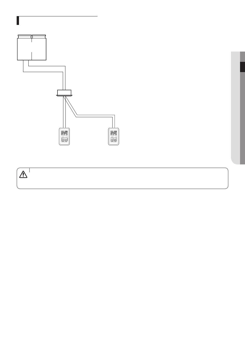
Controlling 2-Remote controller
2-Remote controller is controlling one indoor unit or a group of indoor units with two remote controllers.
Outdoor Unit
Indoor Unit
COM1(F1, F2)
Wired Remote
Controller (Main)
COM2(F3, F4)
Wired Remote
Controller (Sub)
t For the sub Wired Remote Controller settings, please refer to the sections about the additional functions of the
Wired Remote Controller. (Refer to 'Additional Functions of Your Wired remote Controller')
0 : Main, 1 : Sub
CAUTION

ENGLISH-12
Wired Remote Controller Installation
Initializing Your Wired Remote Controller Communication
If the number of indoor unit is decreased while you are using your remote control to control one indoor unit or a group of
indoor units, then you need to initialize your remote controller communication.
Press the [
] and [Set] buttons at the same time for more than ve seconds.
f Your Wired Remote Controller will be initialized, and the device will search for the indoor units connected to your Wired
Remote Controller again.
ENGLISH-13
02 INSTALLATION
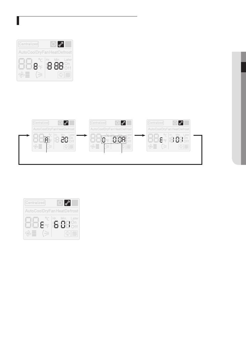
Errors Displayed on Your Wired Remote Controller
Error codes for the Wired Remote Controller and the product connected to your Wired Remote Controller will be displayed in
the LCD display.
LCD Display
When an Error Occurs in Your Indoor/Outdoor Units (Product Group Display: A)
f The product address for the error will be displayed, followed by the error code.
Example : Error 101 occurs for Indoor Unit no. 10 (Decimal digits)
Indoor Unit
Outdoor unit address
(hexadecimal digits)
Indoor unit address
(hexadecimal digits)
When an Error Occurs in Your Wired Remote Controller
f Only an error code will be displayed. (No address will be displayed.)
Example : Error 601 has occurred at your Wired Remote Controller.

ENGLISH-14
Wired Remote Controller Installation
Wired Remote Controller Error Codes
Display Description
Communication error between wired remote controller and indoor units (When communication is lost
for over 3 minutes after detecting the indoor unit and the wired remote controller)
No communication between Main and Sub wired remote controllers.
No communication between wired remote controller and indoor units
- Exceeded maximum number of indoor unit connection (16 rooms)
3FTFUJTSFRVJSFEBGUFSDIFDLJOHUIFOVNCFSPGJOEPPSVOJUT
Two or more wired remote controllers set as Sub.
EEPROM Error
t For the error codes for your indoor/outdoor units, refer to the installation manual of each device.
CAUTION
[Setting/Cancelling the Mode master indoor unit]
t Mode master indoor unit setting is simply selecting an indoor unit that will become standard among many
indoor units to prevent mixed operation (which one or more indoor units operating in dierent operation mode).
- Setting: Connect just 1 indoor unit and stop the operation. Then press and hold the [Mode] button for 5
seconds to set the indoor unit as ‘Mode master indoor unit’.
- Cancelling: Connect just 1 indoor unit and stop the operation. Then press and hold the [Fan Speed] button
for 5 seconds to cancel the ‘Mode master indoor unit’ setting.
NOTE

ENGLISH-15
03 OTHERS
Wired Remote Controller Installation/Service Mode
Additional Functions of Your Wired Remote Controller
Data bit
Main Menu
Sub-menu
12
1. If you want to use the various additional functions for your Wired Remote Controller, press the [Mode] and [Set] buttons
at the same time for more than three seconds.
f You will enter the additional function settings, and the main menu will be displayed.
2. Refer to the list of additional functions for your Wired Remote Controller on the next page, and select the desired menu.
f Using the [
]/[ ] buttons, select a main menu number and press the [Timer] button to enter the sub-menu setting
screen.
f Using the [
]/[ ] buttons, select a sub-menu number and press the [Timer] button to enter data setting screen.
f When you enter the setting stage, the current setting will be displayed.
f Refer to the chart for data settings.
f Using the [
]/[ ] buttons, select the settings. Press the [Timer] button to move to the next setting.
f Press the [Set] button to save the settings and exit to the sub-menu setting screen.
f Press the [Air Swing] button to exit to normal mode.
t While setting the data, you can use the [Fan Speed]/[Timer] buttons to set the range of Data bit.
t While conguring the setting, press the [Air Swing] button to exit to the setting sub-menu without saving your
changes.
NOTE
ENGLISH-16
Wired Remote Controller Installation/Service Mode
Additional Functions of Your Wired Remote Controller
t ‘NONE’ will be displayed if the indoor unit does not support the function. In some cases, the setting may not
possible or it may be not applied though it is set on the unit.
t If communication initialization is needed after the setting, the system will reset automatically and
communication will be initialized.
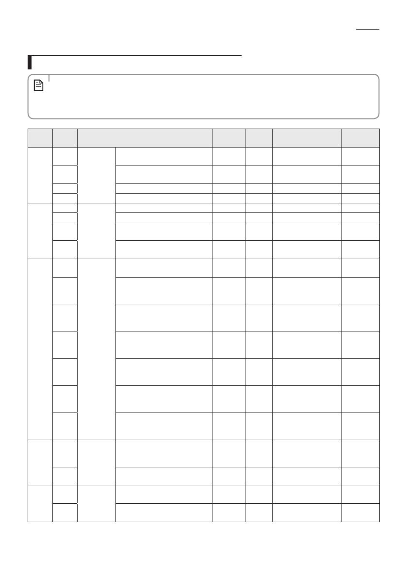
NOTE
Main
Menu
Sub
Menu
Function Default
Number
of pages
Description Remarks
0
1
Reset
Reset option setting of the wired
remote controller
0 1 0 - Disable, 1 - Reset
2
Reset wired remote controller as
factory default setting
0 1 0 - Disable, 1 - Reset
3 Power Master Reset 4)* 0 1 0 - Disable, 1 - Reset
4 Addressing Reset 0 1 0 - Disable, 1 - Reset
1
1
Wired
remote
controller
information
Check the number of indoor units 0 1 0~16
2 Check the number of ERV units 0 1 0~16 No function
3
Check the Micom Code of wired
remote controller
none 3 Micom code
4
Check the program version of
wired remote controller
none 3 Updated date
2
1
Address/
option
setting 2)*
Indoor unit setting (Target) View Master 3
Address of the
registered device
2
Set/Check the MAIN address of the
indoor unit
Main
address of
the target
1
MAIN address
[00H~4FH (hexadecimal
digits)]
3
Set/Check the RMC address of the
indoor unit
RMC
address of
the target
1
Group address
[00H~FEH (hexadecimal
digits)] 5)*
4
Set/Check the product option of
the indoor unit
Basic option
of the
target
10 1)* Indoor unit option code
5
Set/Check the installation option 1
of the indoor unit
Install
option of
the target
10 1)*
Refer to the installation
manual of the
connected indoor unit
6
Set/Check the installation option 2
of the indoor unit
Install (2)
option of
the target
10 1)*
Refer to the installation
manual of the
connected indoor unit
7 MCU/Port address setting
MCU
address of
target
2
MCU address (00 to 15)
Port address (A to F)
3
1
Set/Check
View Master
Set/check indoor unit View Master
Indoor
Units View
Master
3
Address of the
registered device
2 Set/check ERV unit View Master
ERV View
Master
3
Address of the
registered device
No function
4
1
Checking the
address of
mode master
indoor unit
Check the address of the mode
master indoor unit
none 3
Address of the mode
master indoor unit
2
Set the mode msater indoor
unit 3)*
none 1
0-Disable, 1-Enable,
2-Cancel
ENGLISH-17
03 OTHERS
Main
Menu
Sub
Menu
Function Default
Number
of pages
Description Remarks
5
1
Set/Check
the optional
function of
the wired
remote
controller
Set Cooling&Heating/Cooling only
indoor unit
01
0-Cooling&Heating,
1-Cooling only
2 Wireless remote controller usage 1 1 0 - Disable, 1 - Enable
3
Setting Main/Sub wired remote
controller
0 1 0 - Main, 1 - Sub
4 Auto mode usage 1 1 0 - Disable, 1 - Enable
5 Temperature display (°C/°F) 0 1
0 - Celsius (°C),
1- Fahrenheit (°F)
6
Temperature adjustment unit (0,
1, 2) [Available when temperature
display is set to Celsius (°C)]
0 1 0 - 1°C, 1 - 0.5°C, 2 - 1°C
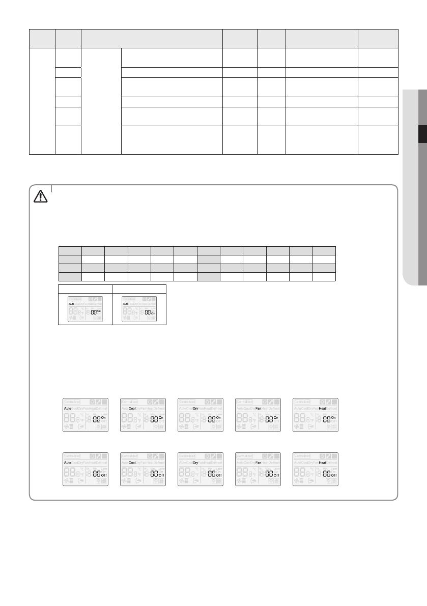
1)* The total option codes are 24 digits. You can set six digits at a time and it is distinguished by page number.
- Press the [Timer] button to go to the next page.
t Option setting is from SEG1 to SEG24.
- SEG1, SEG7, SEG13, SEG19 cannot be set and will not be displayed.
- SEG2 is a type of option and it cannot be set.
- ON will be displayed when setting the SEG2~SEG6 and SEG8~SEG12 and OFF will be displayed when setting
the SEG14~18 and SEG20~24.
t Check the operation mode indicator, ON and OFF indicator to distinguish which SEG are displayed.
SEG2~SEG6, SEG8~SEG12
- ON (Auto
p Cool p Dry p Fan p Heat)
SEG14~SEG18, SEG20~24
- OFF (Auto
p Cool p Dry p Fan p Heat)
CAUTION
SEG1 SEG2 SEG3 SEG4 SEG5 SEG6 SEG7 SEG8 SEG9 SEG10 SEG11 SEG12
0XXXXX1XXXXX
SEG13 SEG14 SEG15 SEG16 SEG17 SEG18 SEG19 SEG20 SEG21 SEG22 SEG23 SEG24
2XXXXX3XXXXX
On(SEG1~12) O(SEG13~24)
p
<SEG 2, 3>
PAGE 1
PAGE 6
PAGE 2
PAGE 7
PAGE 3
PAGE 8
PAGE 4
PAGE 9
PAGE 5
PAGE 10
<SEG 14, 15>
<SEG 4, 5>
<SEG 16, 17>
<SEG 6, 8>
<SEG 18, 20>
<SEG 9, 10>
<SEG 21, 22>
<SEG 11, 12>
<SEG 23, 24>
p
p
p
p
p
pp
p
ENGLISH-18
Wired Remote Controller Installation/Service Mode
2)* When setting the address/option, you can set the target indoor unit by selecting submenu 1.
3)* Setting is available when there is only 1 indoor unit connection and while the indoor unit operation is not operating.
4)* Power Master Reset is a setting needed to supply optimized power to wired remote controller when multiple indoor units
are connected to wired remote controller in a group.
5)* RMC(1) : 0~F / RMC(2) : 0~F (hexadecimal digits)
When RMC(1) is set as F, RMC(2) setting is only available up to E. (RMC(1): Group channel, RMC(2): Group address)
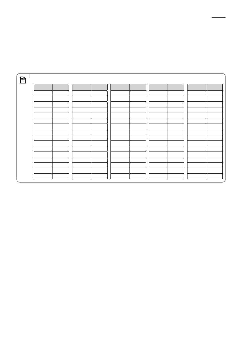
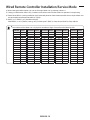
t Main address of the indoor unit is displayed in hexadecimal digits. Please refer to the following table.
NOTE
Hexadecimal Decimal Hexadecimal Decimal Hexadecimal Decimal Hexadecimal Decimal Hexadecimal Decimal
00 0 1016 2032 3048 4064
01 1 1117 2133 3149 4165
02 2 1218 2234 3250 4266
03 3 1319 2335 3351 4367
04 4 1420 2436 3452 4468
05 5 1521 2537 3553 4569
06 6 1622 2638 3654 4670
07 7 1723 2739 3755 4771
08 8 1824 2840 3856 4872
09 9 1925 2941 3957 4973
0A 10 1A 26 2A 42 3A 58 4A 74
0B 11 1B 27 2B 43 3B 59 4B 75
0C 12 1C 28 2C 44 3C 60 4C 76
0D 13 1D 29 2D 45 3D 61 4D 77
0E 14 1E 30 2E 46 3E 62 4E 78
0F 15 1F 31 2F 47 3F 63 4F 79
ENGLISH-19
03 OTHERS
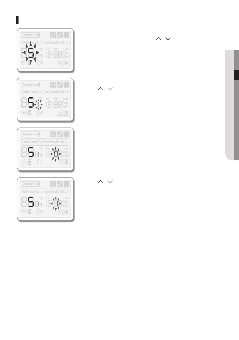
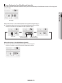
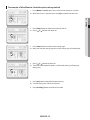
The example of Wired Remote Controller option setting method
1. Press [Mode] and [Set] buttons at the same time for more than 3 seconds.
f When Main menu is displayed, press the [
]/[ ] button to select no.5.
2. Press [Timer] button to select the number you will set.
f Press [
]/[ ] button and select no.1
3. Press [Timer] button to enter the data setting stage.
f When you enter the setting stage, the current setting value will be displayed.
4. Press [ ]/[ ] button to select no.1.
f The wired remote controller option is set from both cooling and heating to
cooling only.
5. Press [Set] button to complete the option setting.
f Save the setting value and exit to sub menu.
6. Press [Air Swing] button to exit to normal mode.

-
 1
1
-
 2
2
-
 3
3
-
 4
4
-
 5
5
-
 6
6
-
 7
7
-
 8
8
-
 9
9
-
 10
10
-
 11
11
-
 12
12
-
 13
13
-
 14
14
-
 15
15
-
 16
16
-
 17
17
-
 18
18
-
 19
19
-
 20
20


Samsung MWR-SH00 Installation guide
- Category
- Split-system air conditioners
- Type
- Installation guide
- This manual is also suitable for
Ask a question and I''ll find the answer in the document
Finding information in a document is now easier with AI
Related papers
-
Samsung MWR-SH00 Installation guide
-
Samsung MWR-SH10N Installation guide
-
Samsung MWR-VH12NDZ Installation guide
-
-
Samsung AN100JSKLKN Installation guide
-
Samsung MWR-WE13 Installation guide
-
-
-
Samsung MWR-WE11N Installation guide
-
Samsung MWR-WE10N Installation guide