18 | English
1 609 92A 32T | (22.6.16) Bosch Power Tools
Remove the batteries from the measuring tool when
not using it for extended periods. When storing for ex-
tended periods, the batteries can corrode and self-dis-
charge.
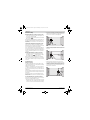
Working with the Rotating Mount RM 1
(see figures A1 – A2)
You can use the rotating mount 13 to rotate the measuring
tool 360° around a central, always visible plumb point. This
enables you to set up the laser lines precisely, without having
to change the position of the measuring tool.
– Place the measuring tool with the guide groove 8 on the
guide rail 14 of the rotating mount 13 and slide the meas-
uring tool to the stop onto the platform.
To disconnect, pull the measuring tool in the opposite di-
rection from the rotating mount.
Positioning possibilities of the rotating mount:
– standing on a flat surface,
– screwed to a vertical surface,
– on metallic surfaces using the magnets 16,
– on metallic ceiling strips using the ceiling clip 17.
Operation
Initial Operation
Protect the measuring tool against moisture and direct
sun light.
Do not subject the measuring tool to extreme tempera-
tures or variations in temperature. As an example, do
not leave it in vehicles for a long time. In case of large vari-
ations in temperature, allow the measuring tool to adjust to
the ambient temperature before putting it into operation.
In case of extreme temperatures or variations in tempera-
ture, the accuracy of the measuring tool can be impaired.
Avoid heavy impact to or falling down of the measuring
tool. Damage to the measuring tool can impair its accura-
cy. After heavy impact or shock, compare the laser lines or
plumb beams with a known horizontal or vertical reference
line or with already checked plumb points.
Switch the measuring tool off during transport. When
switching off, the levelling unit, which can be damaged in
case of intense movement, is locked.
Switching On and Off
To save energy, only switch the measuring tool on when you
are using it.
Do not leave the switched-on measuring tool unattend-
ed and switch the measuring tool off after use. Other
persons could be blinded by the laser beam.
–To switch on the measuring tool, slide the On/Off switch 2
to position “” (for working without automatic level-
ling) or to position “” (for working with automatic
levelling).
As soon as it is switched on, the measuring tool emits laser
lines from the exit openings 1.
–To switch off the measuring tool, slide the On/Off switch 2
to position “”.
The pendulum unit is locked when the tool is switched off.
When exceeding the maximum permitted operating tempera-
ture of 50 °C, the measuring tool switches off to protect the
laser diode. After cooling down, the measuring tool is ready
for operation and can be switched on again.
Automatic Shut-off
When no button on the measuring tool is pressed for approx.
120 minutes, the measuring tool automatically switches off
to save the batteries.
–To switch the measuring tool back on after automatic shut-
off, you can either slide the On/Off switch 2 to position
“” first and then switch the measuring tool back on, or
press either button 5 or button 6.
Deactivating the Automatic Shut-off:
– To deactivate automatic shut-off, hold down button 6 for at
least 3 s with the measuring tool switched on. If automatic
shut-off is deactivated, the laser lines will flash briefly as
confirmation.
Note: If the operating temperature exceeds 45°C, automatic
shut-off can no longer be deactivated.
Activating the Automatic Shut-off:
– To activate the automatic shut-off, switch the measuring
tool off and then on again.
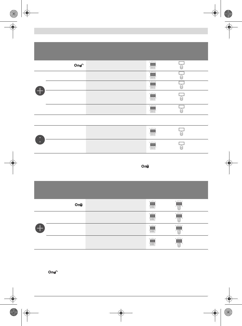
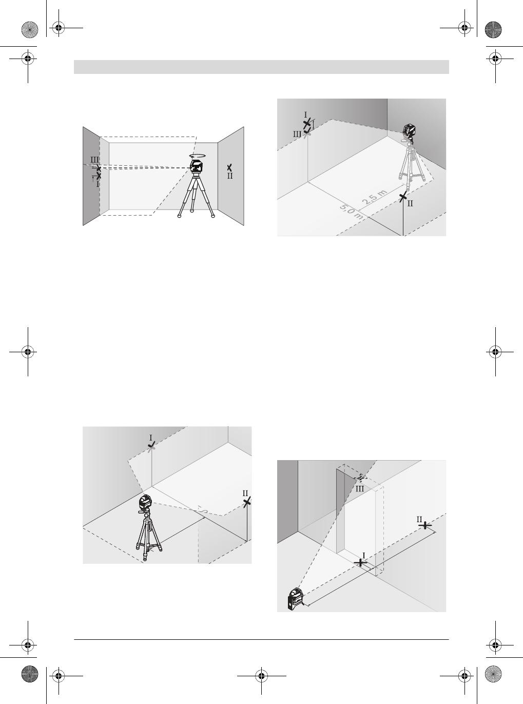
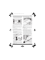
Setting the operating mode (see figures B1–F1)
The measuring tool has several operating modes between
which you can switch at any time:
–Cross-line and point operation: The measuring tool gen-
erates a horizontal and a vertical laser line facing front-
ward, a vertical laser point facing upward and a vertical la-
ser point facing downward.
The laser lines cross at a 90° angle.
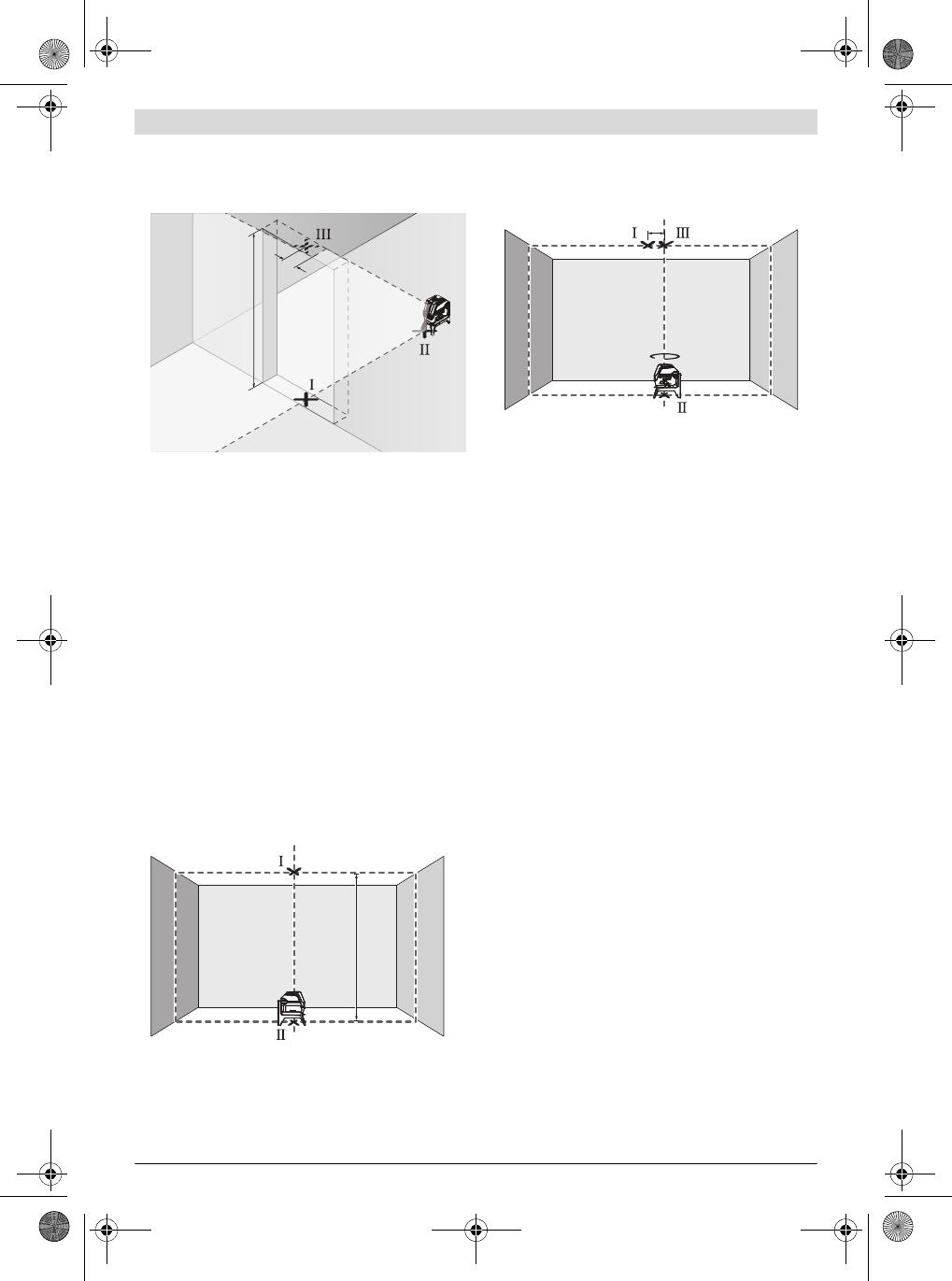
–Point operation: The measuring tool generates a vertical
laser point facing upward and a vertical laser point facing
downward.
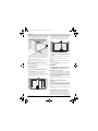
–Horizontal line operation: The measuring tool generates
a horizontal laser line facing frontward.
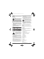
–Vertical line operation: The measuring tool generates a
vertical laser line facing frontward.
If the measuring tool is positioned in the room, the vertical
laser line is displayed on the ceiling beyond the upper laser
point.
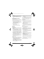
If the measuring tool is positioned directly against a wall,
the vertical laser line generates an almost completely all-
round laser line (360° line).
All modes except for point operation can be selected both
with and without automatic levelling.
OBJ_BUCH-2637-002.book Page 18 Wednesday, June 22, 2016 4:13 PM


 1
1
 2
2
 3
3
 4
4
 5
5
 6
6
 7
7
 8
8


Bosch GLL2-10 User manual
Bosch PCL 20 Original Instructions Manual
Alto 300 HV User manual
Bosch GLL 2 Owner's manual
Bosch GLL 2-80 P Professional Original Instructions Manual
Bosch GLL 3-50 Owner's manual
Bosch PLL 360 User manual
Bosch Appliances GLL2-50 User manual
Bosch Power Tools GCL25 User manual
 CST Berger Lasermark Wizard LM30 Original Instructions Manual
Skil LL0516 AA Owner's manual
Makita SK106DNAX-LD050 User manual
Hilti PM 2-LG Operating instructions
Hilti 3520501 User manual
Kreator KRT706320 Owner's manual
